Mac offered me the chance to install his prototype/ first generation Cold Air Intake and/or Cabin Air Filter. Why the and/or phrase? The system is actually 2 parts. First part being a Cabin Air Filter. Jeep was nice enough to install a large screened intake right on top of the Cowl so that you can get air for the fan. While this is a great idea and provides lots of air flow, it has the nasty habit of sucking in all of that tail dust and blowing it right into the interior of the vehicle, usually the next day. We all know how much our significant other loves that. The second part of the system is a Cold Air Intake. This part takes air right from the outside, completely outside of the engine compartment.
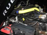
Once I had the kit in hand, I just needed a willing volunteer to let me cut his jeep up. A friend of mine graciously volunteered his Jeep to have the system installed. Thanks Steve. Not only did he let me use his Jeep, but he left it with me and didn't even watch me cut it up. This is the install as I worked on it, and the product is still in the prototype stage, so it may change after I did it. The tube in these pictures was painted at a later step to allow for visibility in the pictures. I recommend a high temperature paint.
This setup is intended for off road use and may not pass local smog regulations. This scoop takes air directly outside and if you try hard enough you can get water into the scoop and then possible into your engine. It's not a snorkle. You can make a shield for the inner filter if you live in an area susceptible to heavy snow melt or torrential downpours.
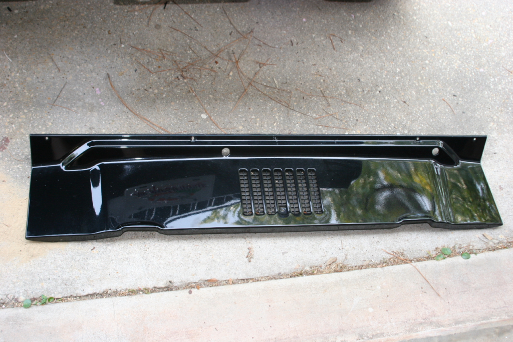
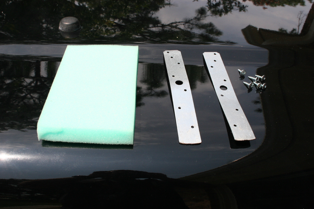
| Here is what comes in the Kit. The system does come unpainted, so you can paint it whatever color you like. |
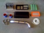
Complete kit.
|
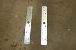
Filter Straps |
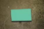
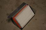
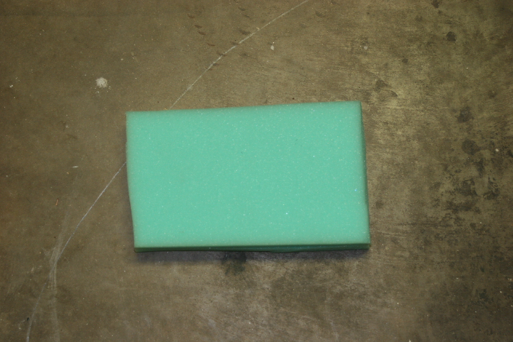
Foam Filter |
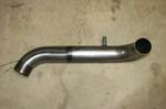
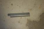
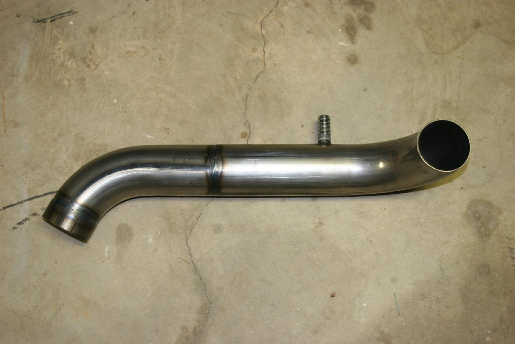
Air Intake Tube |
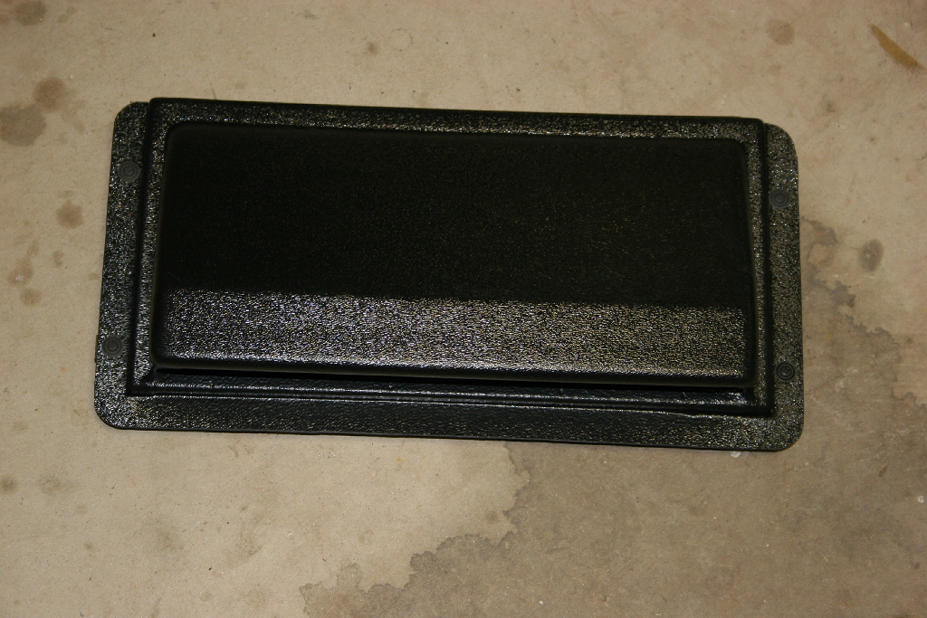
Hood Scoop |
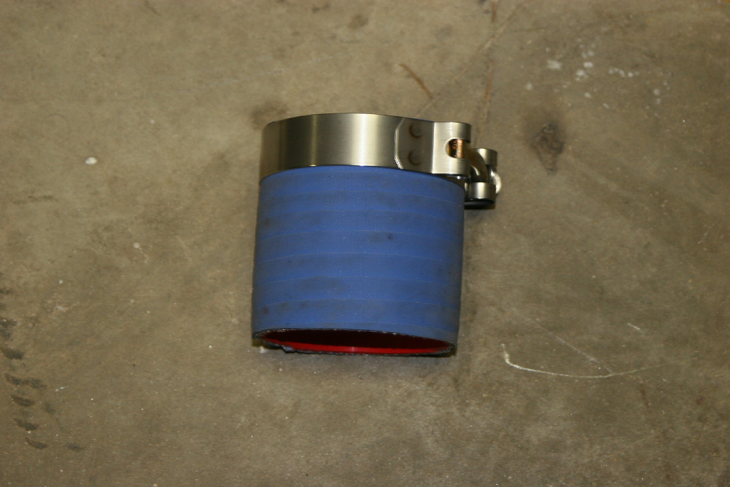
Tube to Throttle Body Connector |
Tube to Baffle Connector |
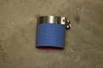
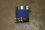
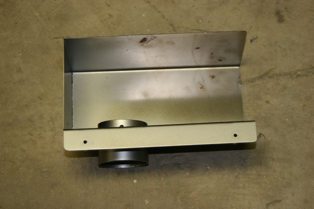
Air Baffle |
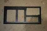
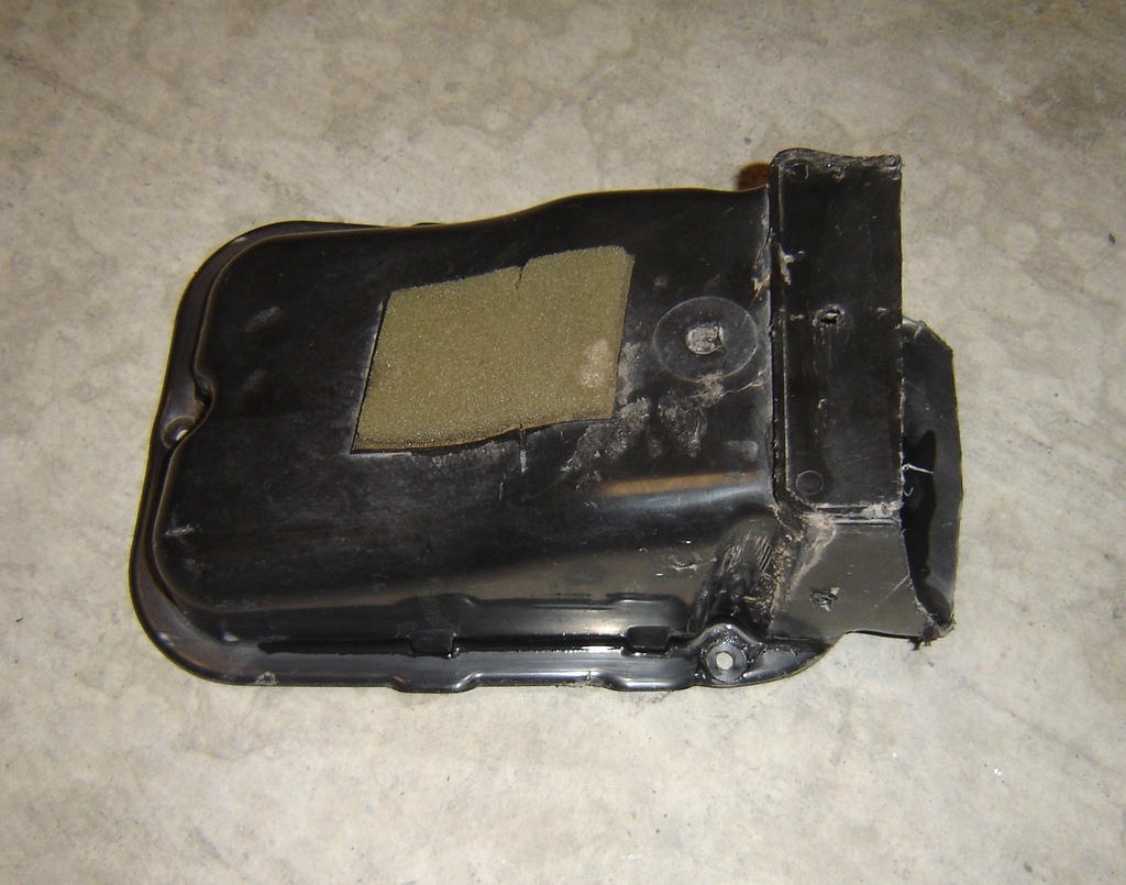
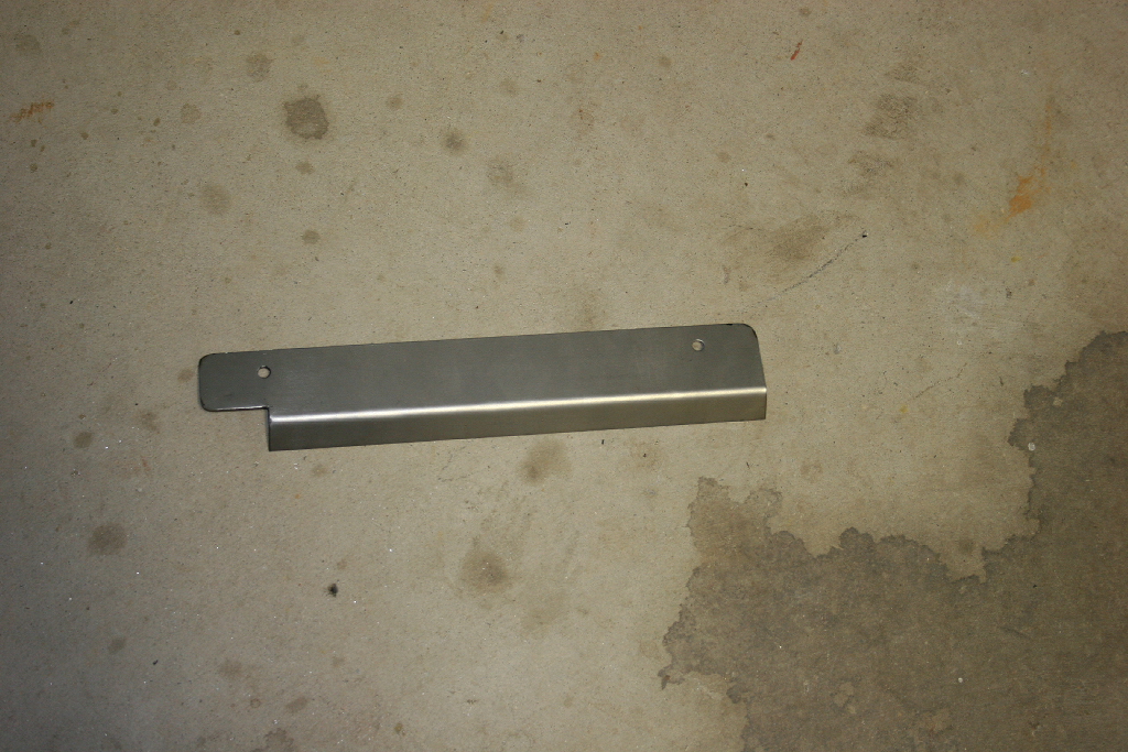
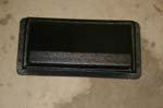
Filter Housing |

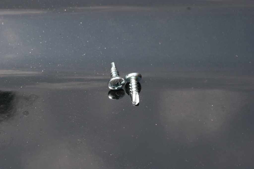
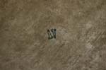
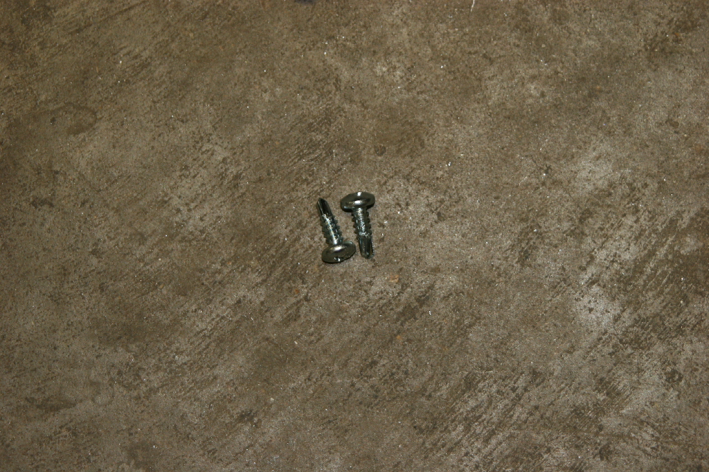
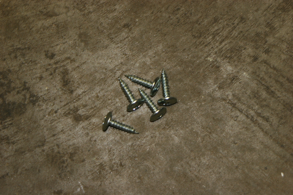
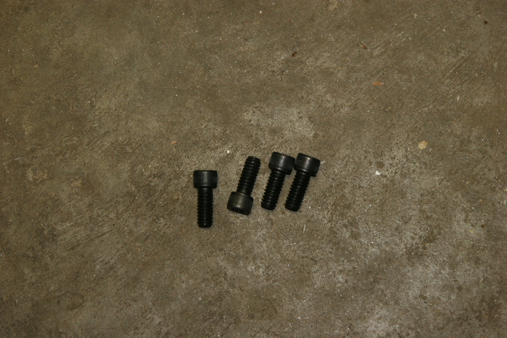
Scoop Screws |
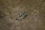
Baffle Screws |
Filter Strap Screws |
| |
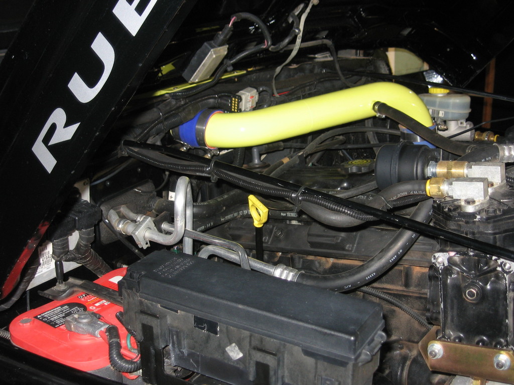
| The box and pipe must be painted prior to installation. We have seen red, white, yellow and black for colors, so the choice is up to you, but high temp paint is recommended. |
 |
 |
| |
| Safety: |
| Disconnect your battery. This is a safety precaution since you will be unplugging sensors and moving cables around. Your battery cable's may require a different size wrench than the 10mm combo wrench that we used. |
 |
| |
| Cowl Removal: |
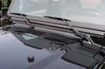
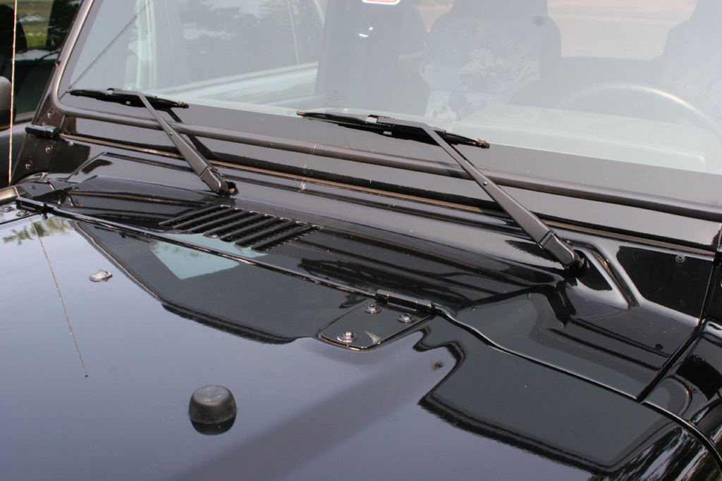
| Remove the windshield wipers by pulling the arm forward and lifting up on the locking tab |
 |
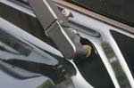
Pull arm forward
|
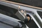
Lift Tab with flat tip screwdriver
|
Remove Arm
|
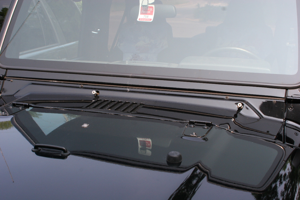
| Remove the cowl. |
 |
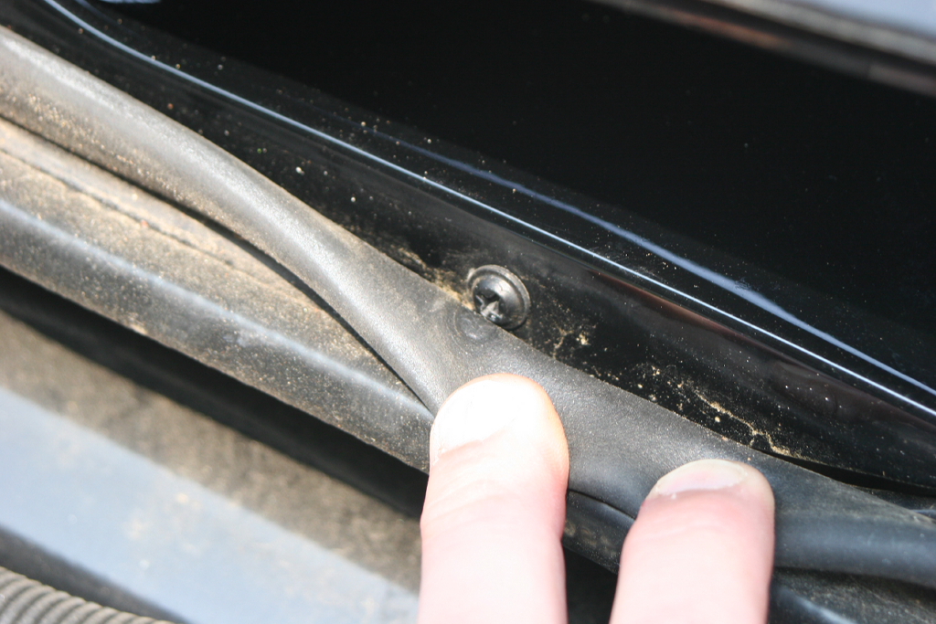
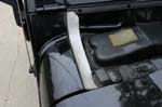
| Open up the hood and remove the weather stripping along the firewall edge of the hood. This will allow you to get to the two screws behind it. |
Weather Stripping
|
Pulls off
|
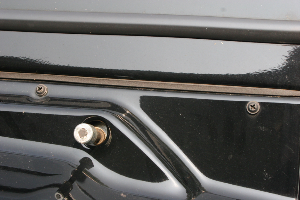
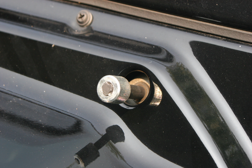
| Remove the two phillips head screws. |

Cowl screws |
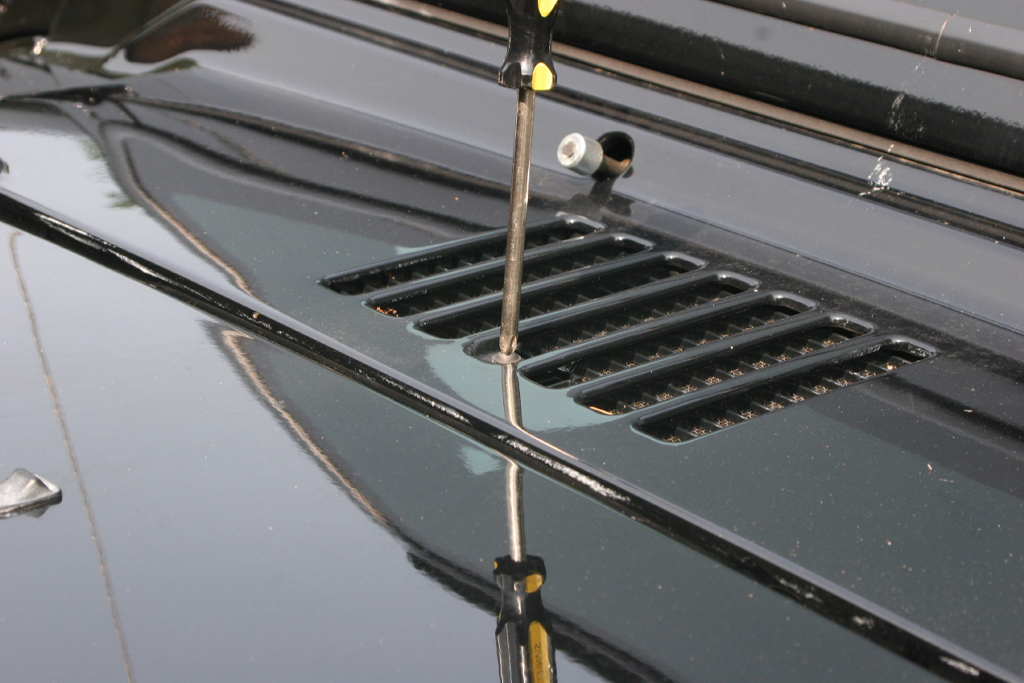
| Remove the four phillips head screws along the windshield edge of the cowl, and the one phillips head screw on the inside of the cowl intake. Save all the screws you removed. You will reuse the 4 long and 2 of the short screws. |
|
|
| Pull up on the leading edge of the cowl and pull it towards the front of the vehicle. Be careful where the wiper pins go through the cowl, they will scrape up the edge of the cowl. |
|
|
| Note: If you are only installing the cabin air filter skip the next section and go to cabin air filter. |
| |
| Air Intake Removal: |
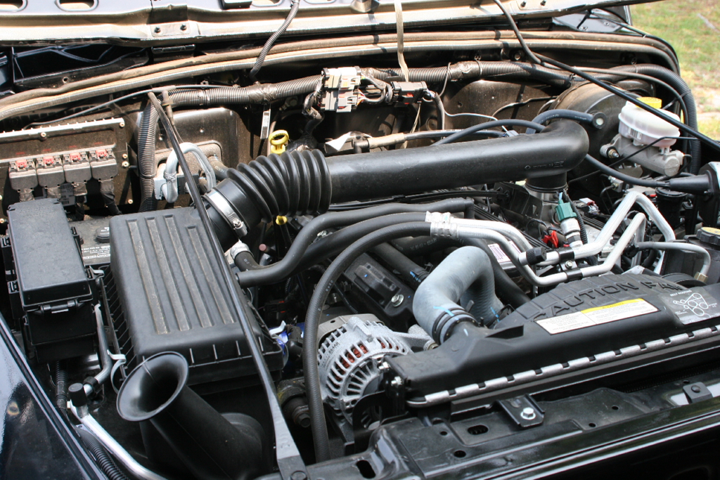
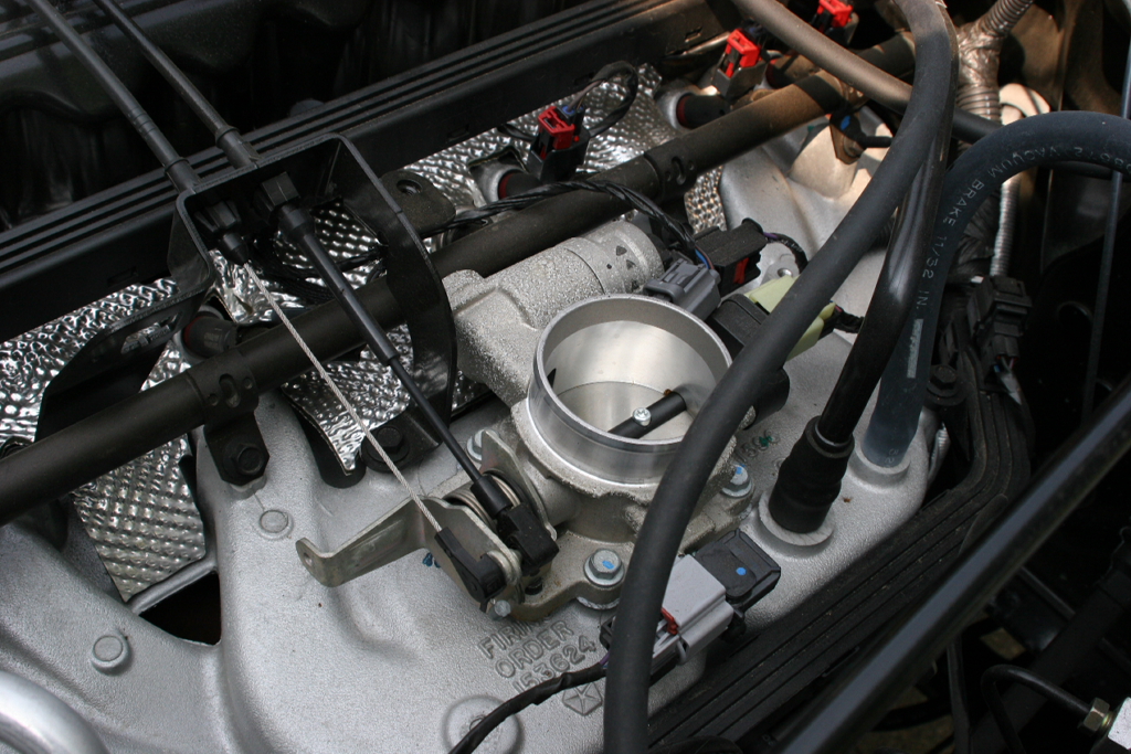
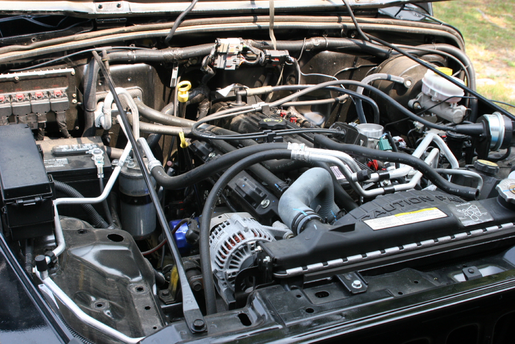
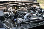
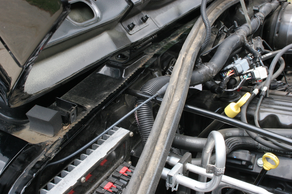
| Clean the area around the throttle body. You will be removing the entire air intake system to the throttle body. |
 |
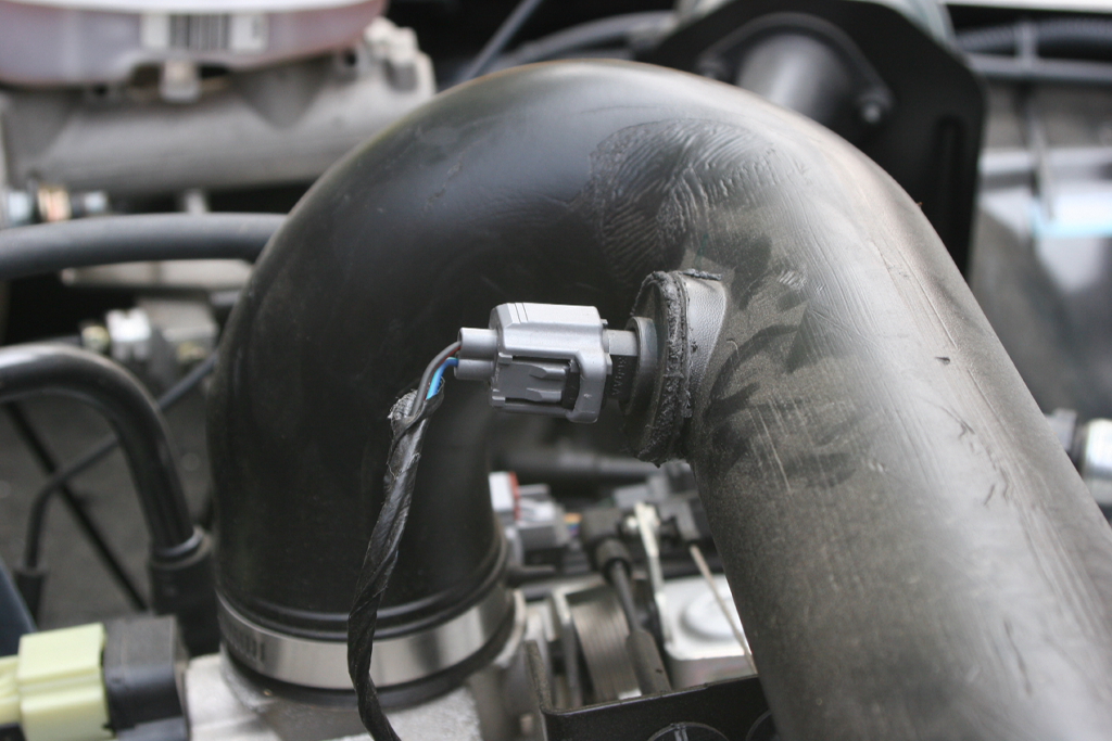
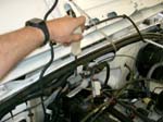
You may need to disconnect the Air Inlet Temperature (AIT) Sensor from the air intake tube if applicable to your vehicle. Push in the tab and remove the electrical connector.
Note: 2005 – 2006 models have AIT. 1997 to 2003 do not have this sensor on the Air Tube. |
 |
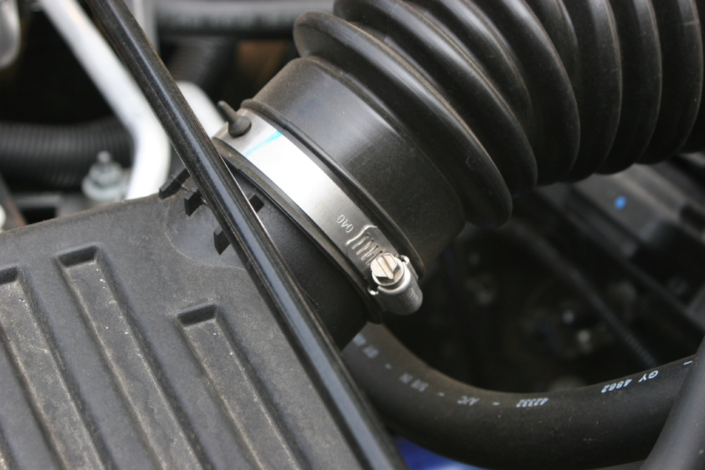
| Loosen the factory clamps at the throttle body and the air filter box with a flat tip screwdriver. You will reuse the factory clamp on the new tube. |
|
|
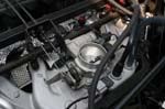
| Be careful with the exposed throttle body. I recommend placing a clean rag over the intake while you are working around it to prevent any material from falling into the intake. |
 |
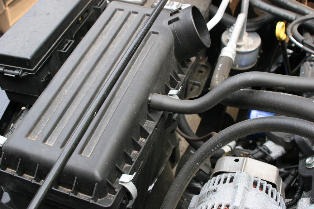
| Remove the valve cover vent tube from the air box or air intake tube. This just pulls off. |
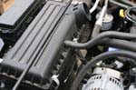 |
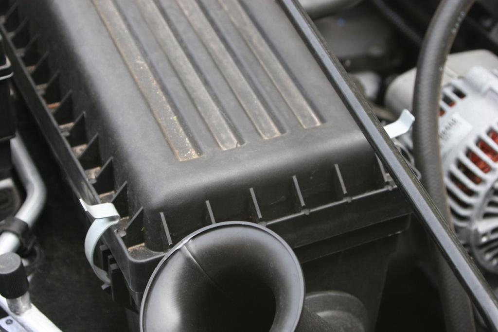
| Undo the clips holding the top of the air filter box on, remove the air filter box, and the air filter. |
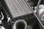 |
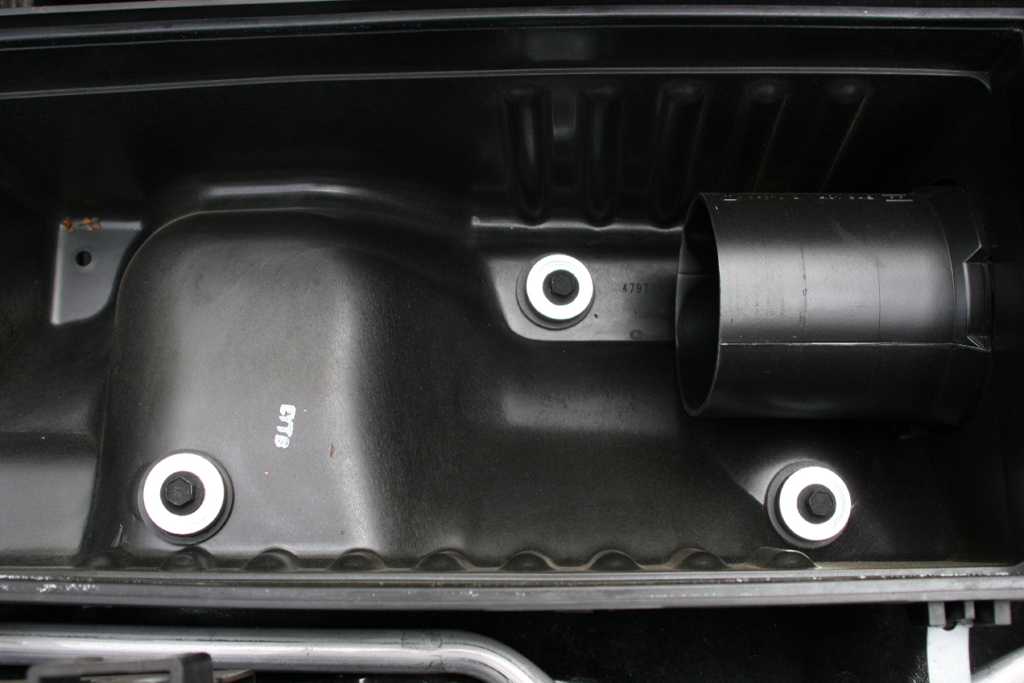
| Remove the 3 screws holding the air filter box to the fender well with a 8mm socket and a 10mm combo wrench underneath. |
|
|
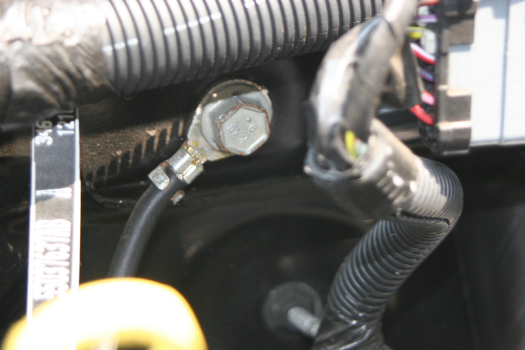
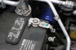
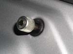
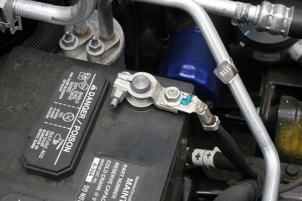
| Undo the starter ground wire with a 15mm socket and extension. |
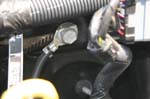 |
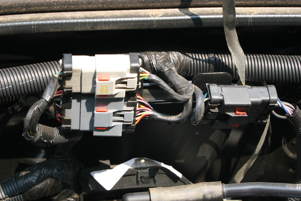
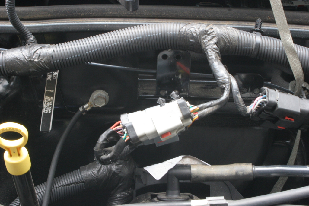
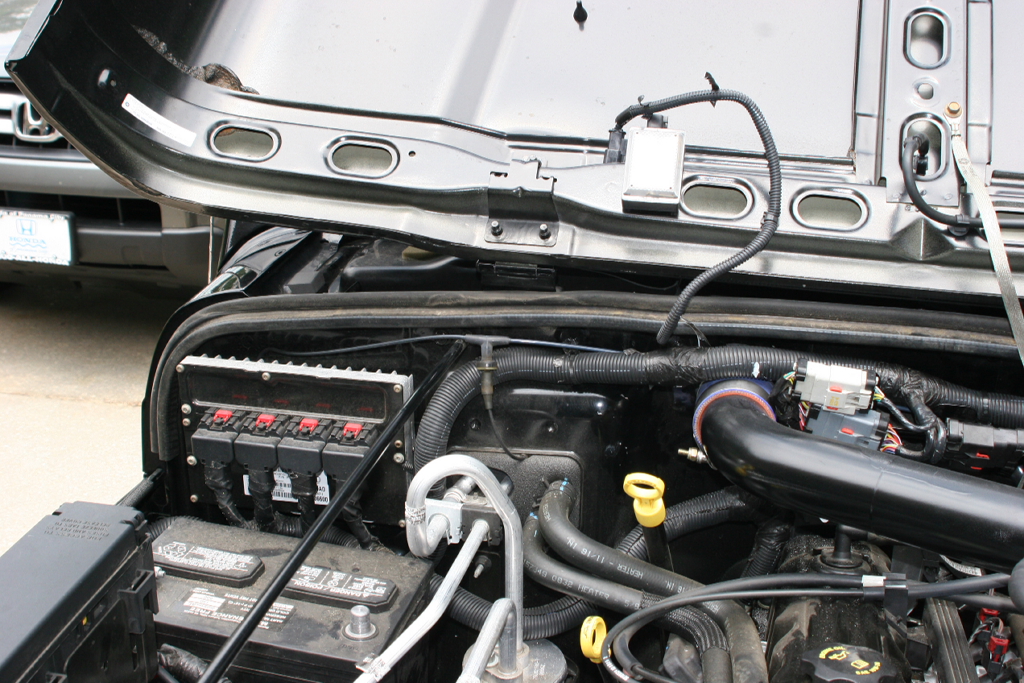
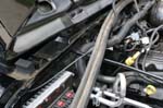
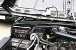
| Unclip the wiring connectors from their bracket so that you have clearance when drilling into your firewall for the intake. |
 |
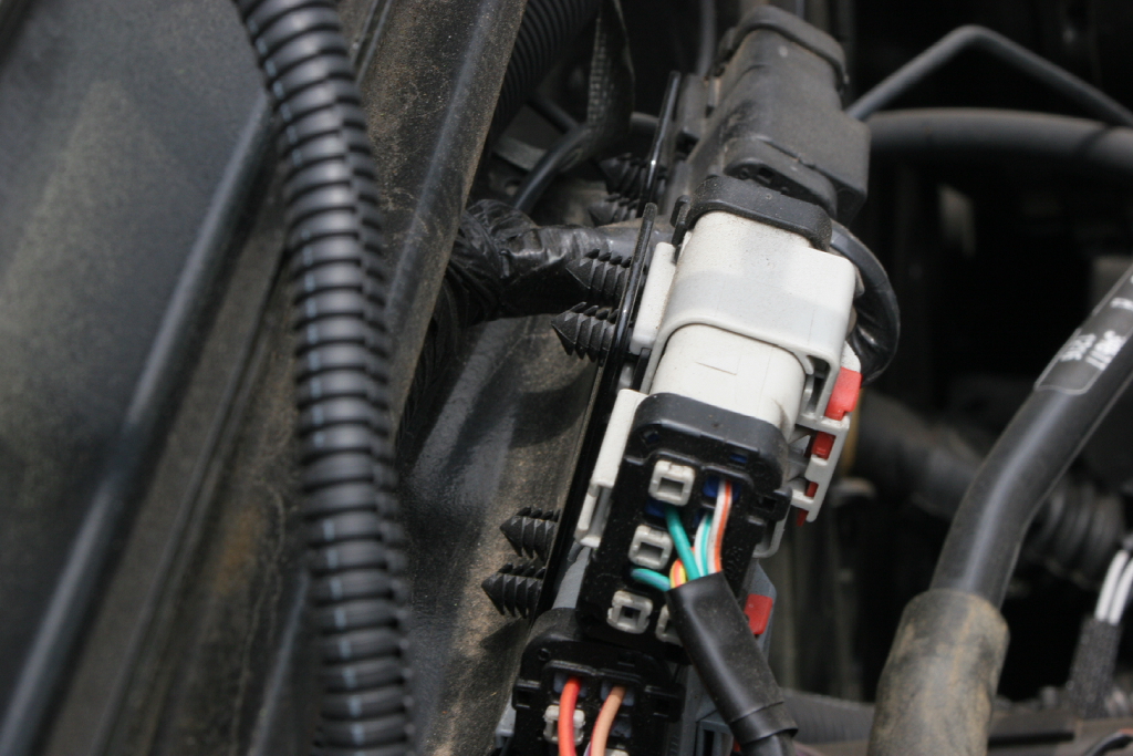
| Remove all three connectors by pulling them off the mount bracket. You may need to slip a flat tip screwdriver between the connector and bracket.
|
|
|
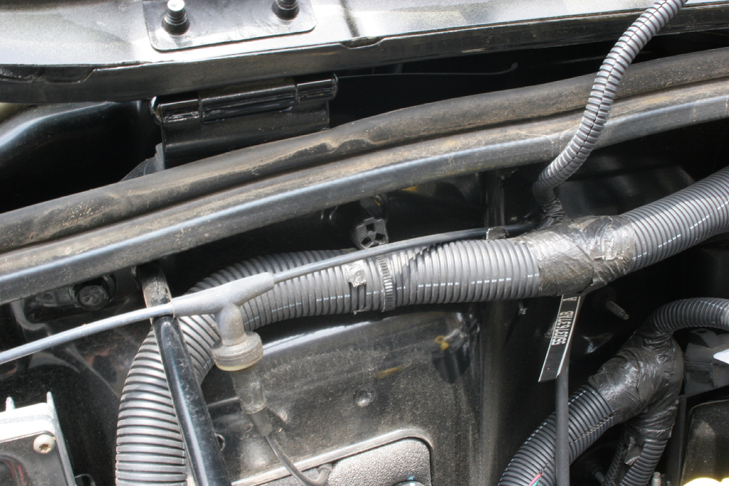
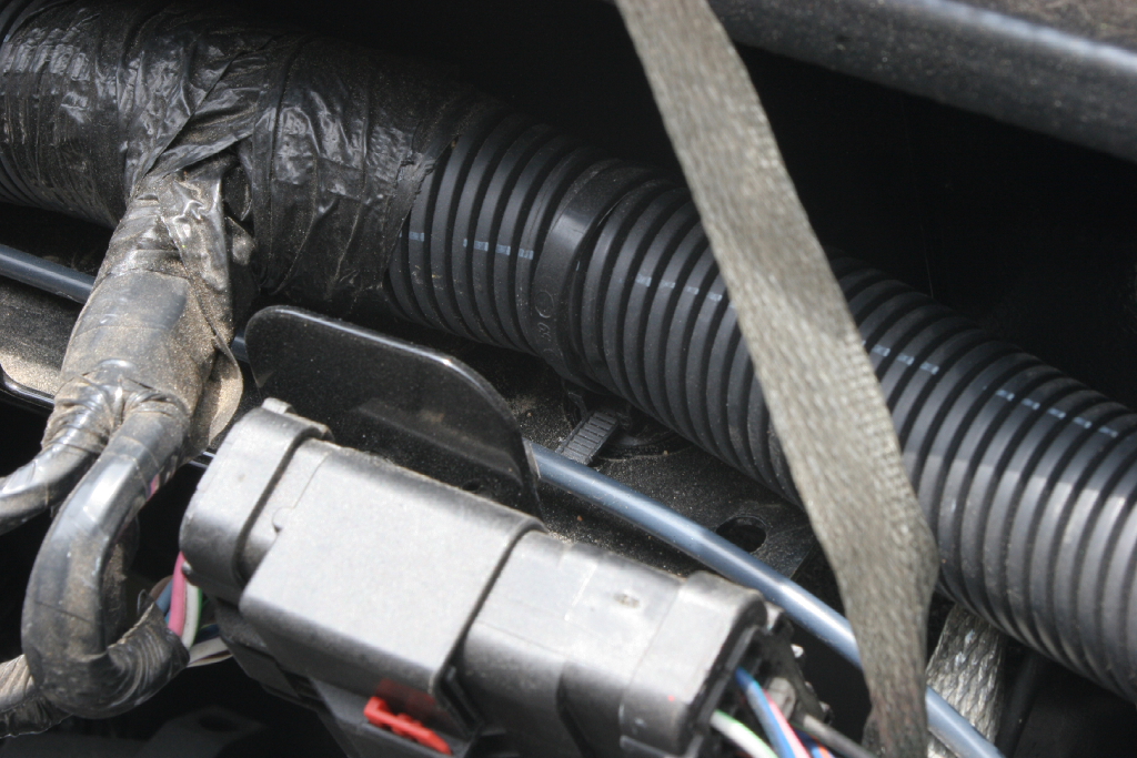
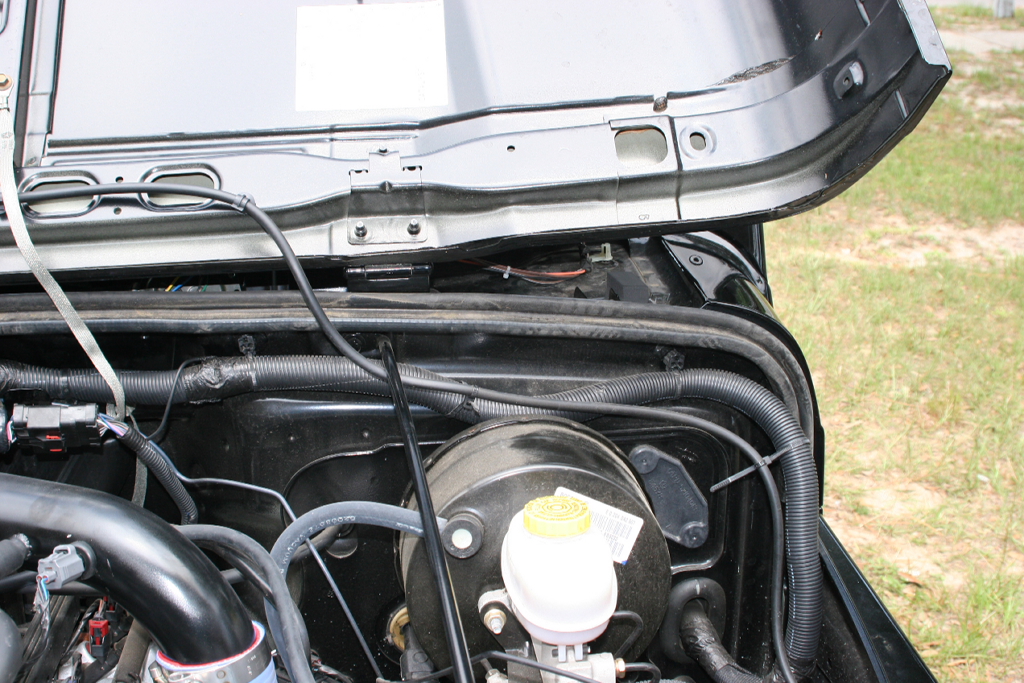
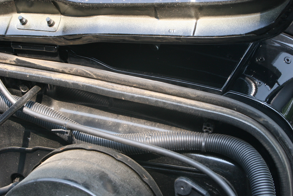
| Pull the two wire straps off of the screws on either side of the hood, and the one wire push strap out of the bracket. This will give you enough slack to move the wire bundle out of the way. We will reconnect these later. |
|
|
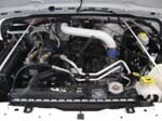
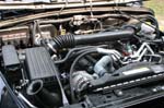
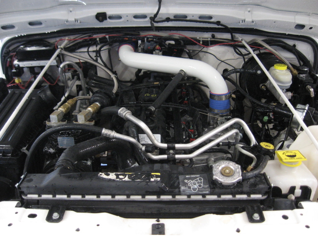
| Everything is now removed from the engine compartment. |
 |
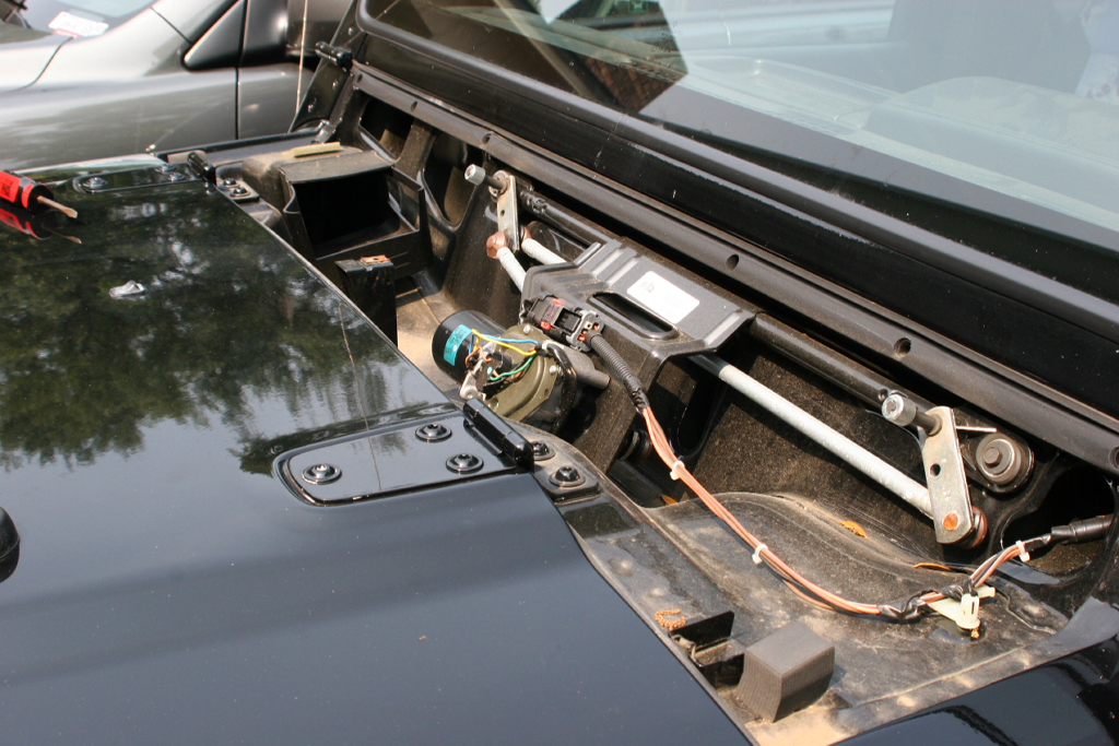
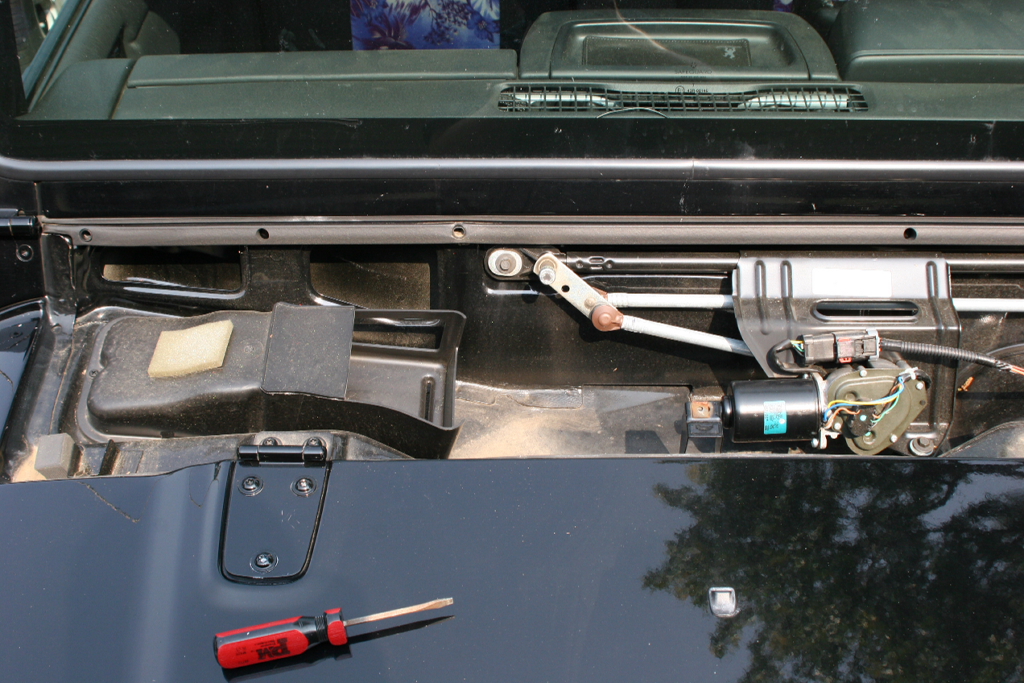
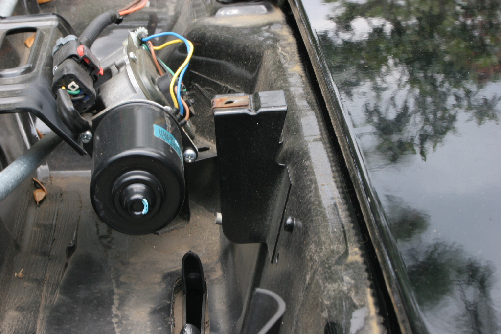
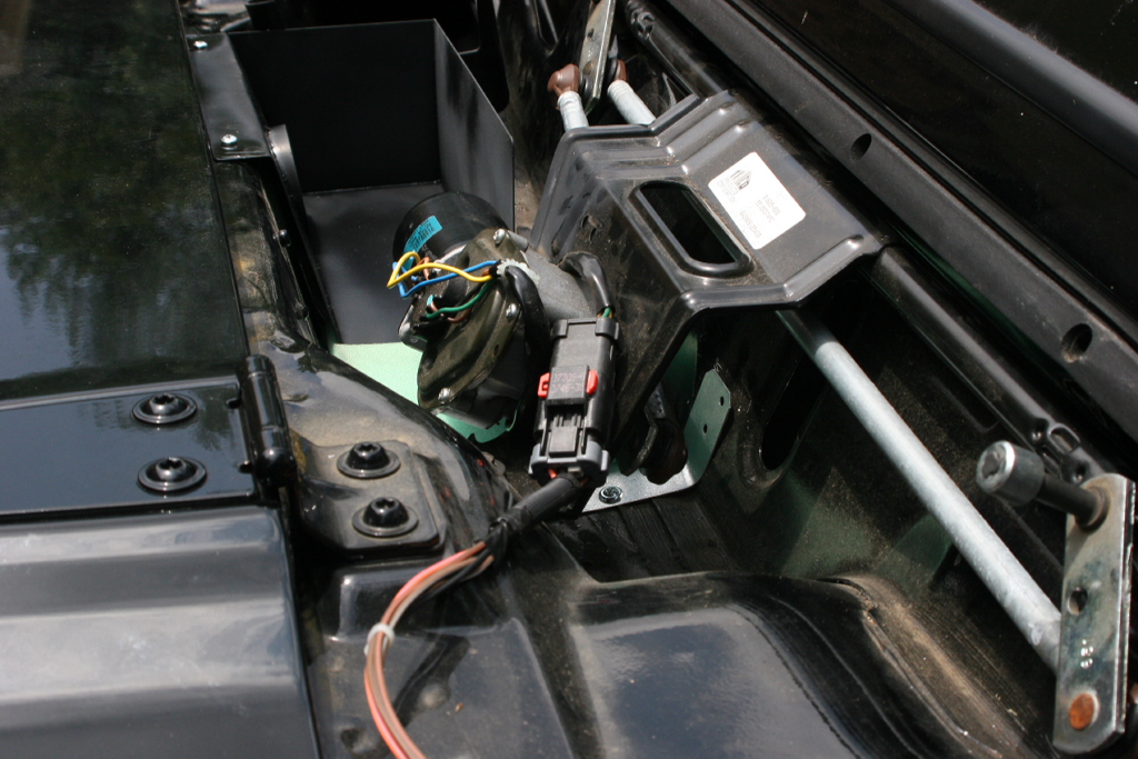
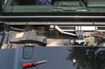
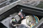
| Remove the wiper motor assembly. |
 |
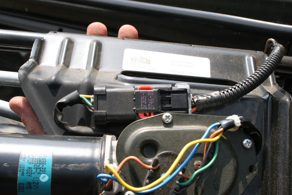
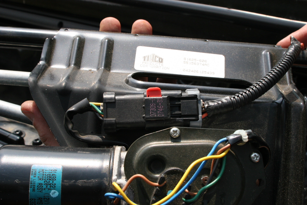
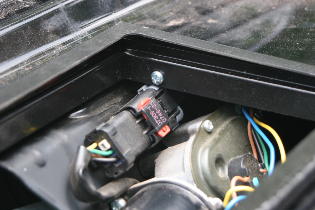
| Disconnect the wiper motor connector. Pull up on the red tab to unlock the connector, push down the tab and disconnect. |
|
|
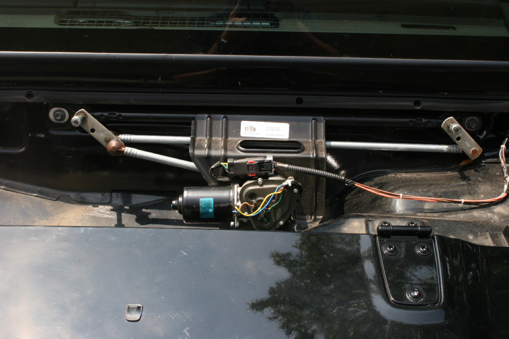
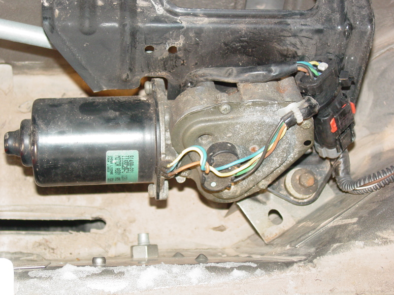
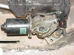
| Remove the wipe motor assembly by removing the three mounting bolts with a 10mm socket. The posts extend back into the cowl assembly so you will need to remove it slowly. |
 |
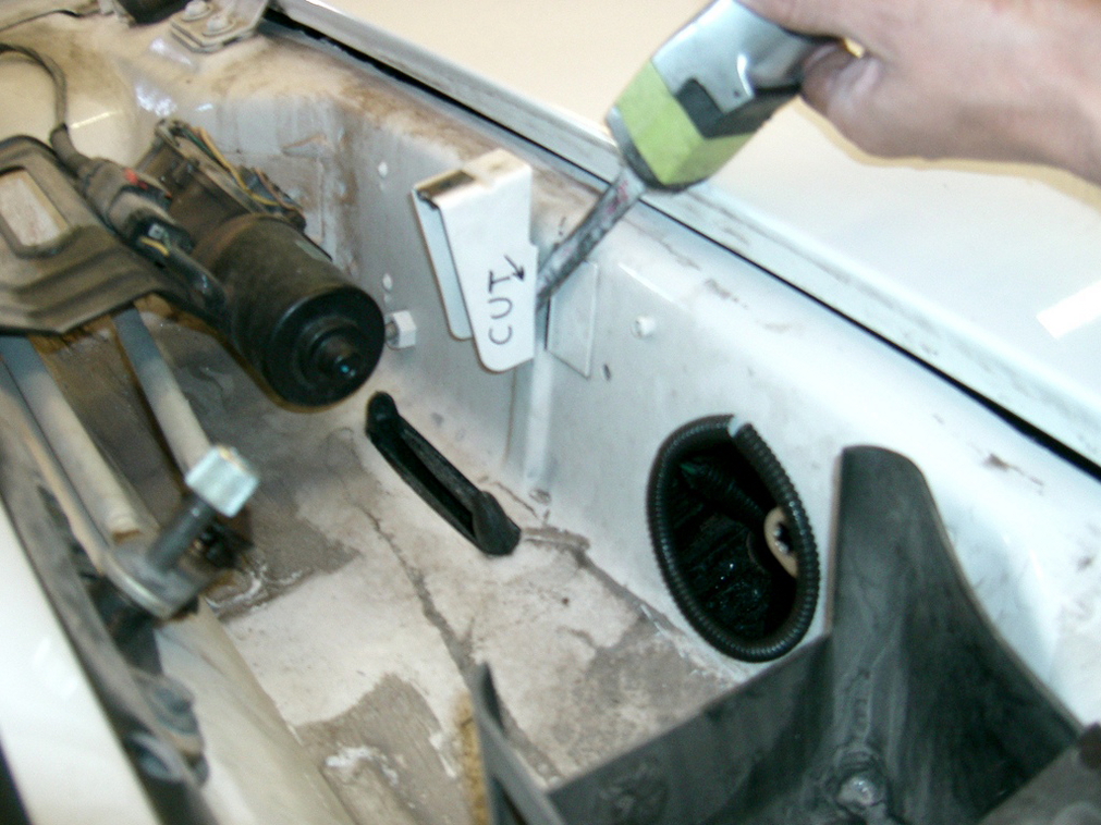
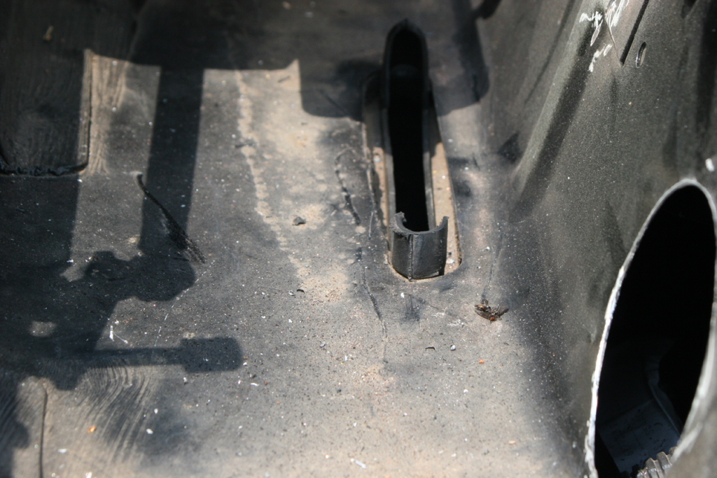
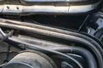
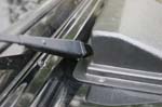
| Remove the center cowl support with a dremel, or hacksaw. |
 |
 |
|
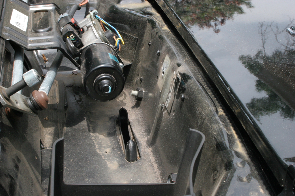
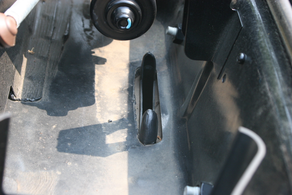
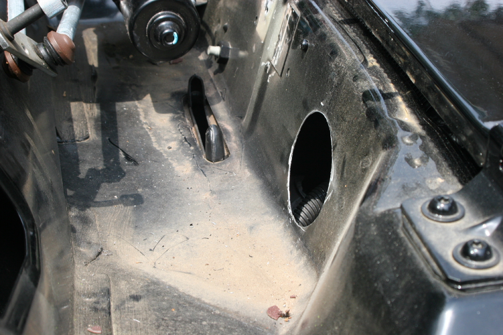
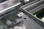
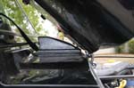
| Trim the cowl drain. Trim the passenger side retaining prong to about 1/4" above the bottom of the cowl area. Test fit the air baffle for clearance and trim as necessary. |
|
|
| You may need to remove the Cover for the vent fan. This is held in by 3 phillips screws.
Optional: Remove and Cut a few inches off the leading edge of the cover, this will allow better air flow into the vent fan. |
 |
 |
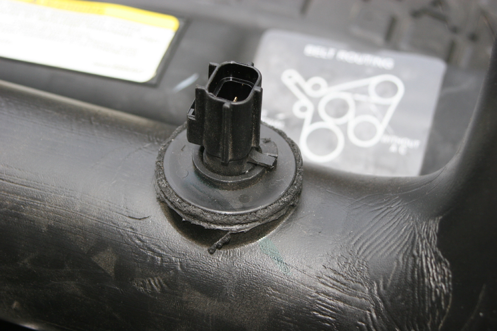
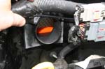
| Remove the stock clamp from the throttle body end of the OEM air tube. |
|
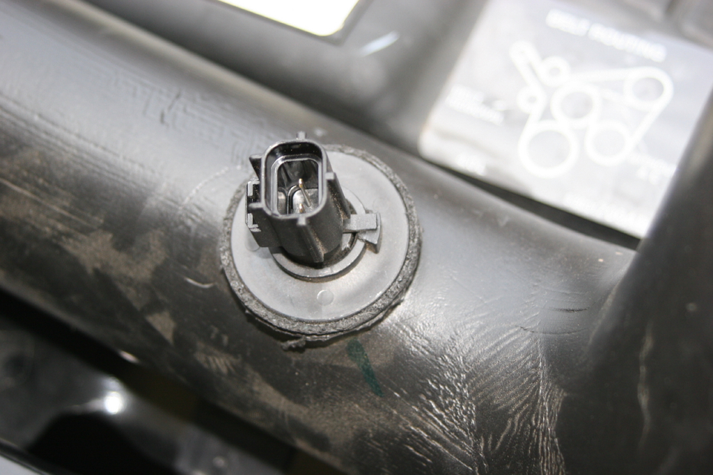
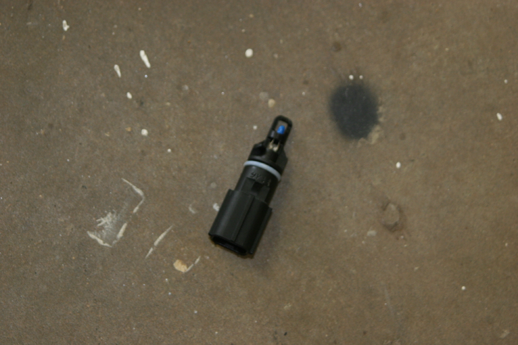
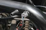
| If equipped remove the IAT sensor from the OEM air tube. The sensor has a tab on it that you will need to lift over the catch on the tube. |
|
|
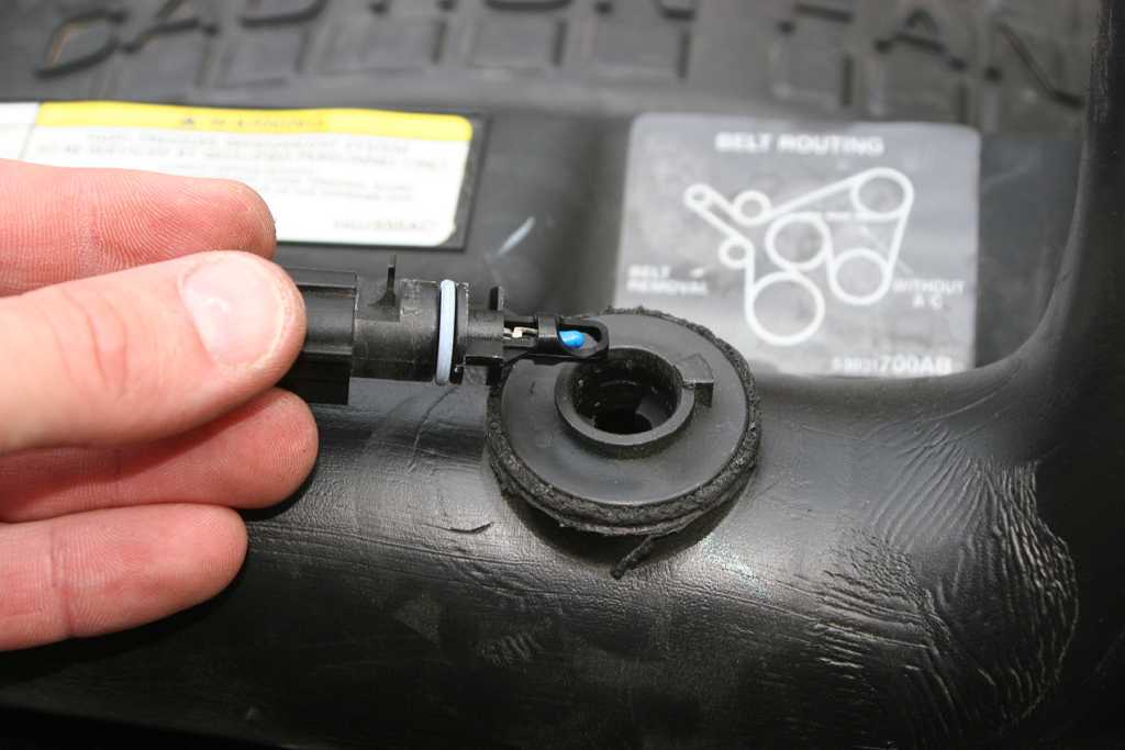
| The sensor is held in by an o-ring seal, so you may need to twist slightly as you pull it out. Place this sensor aside where it will not get damaged. |
 |
| |
| Installation: |
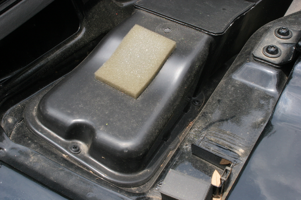
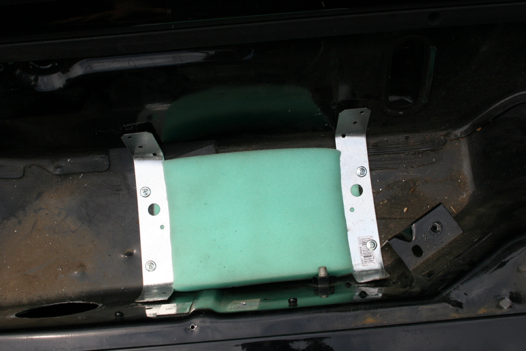
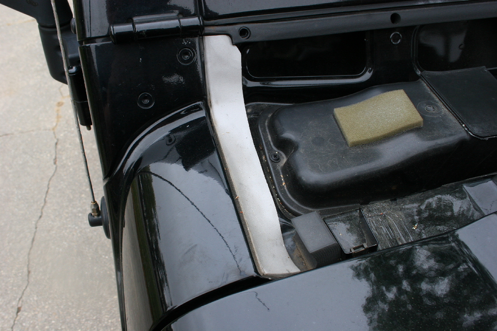
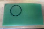
| The provided foam filter goes over the cowl drain and is held down by the provided straps. The filter will allow any water that may get in to drain out. (Water should not be a problem with the scoop installed) |
 |
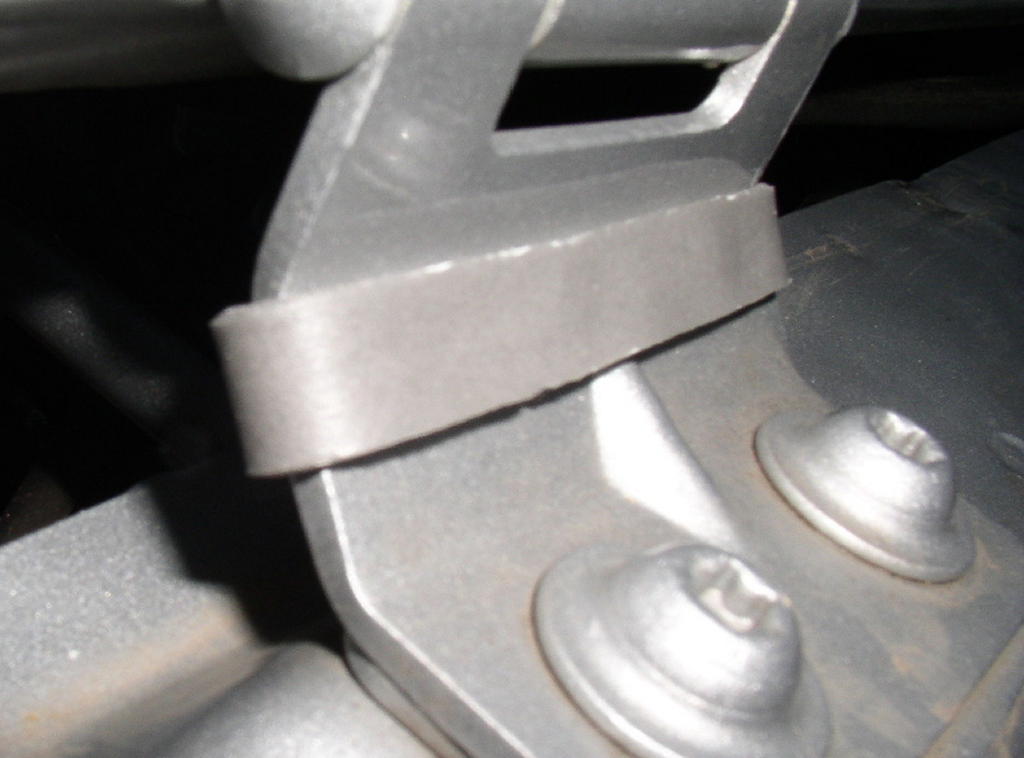
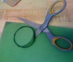
| Position the filter over the cowl drain. It will be off-set to the drivers side for the straps. Bend the straps to fit the curve of the cowl area. Use the self drilling sheet metal screws to hold the filter straps down to the cowl. I recommend removing the screws and applying paint to the drilled holes before reinstalling. |
 |
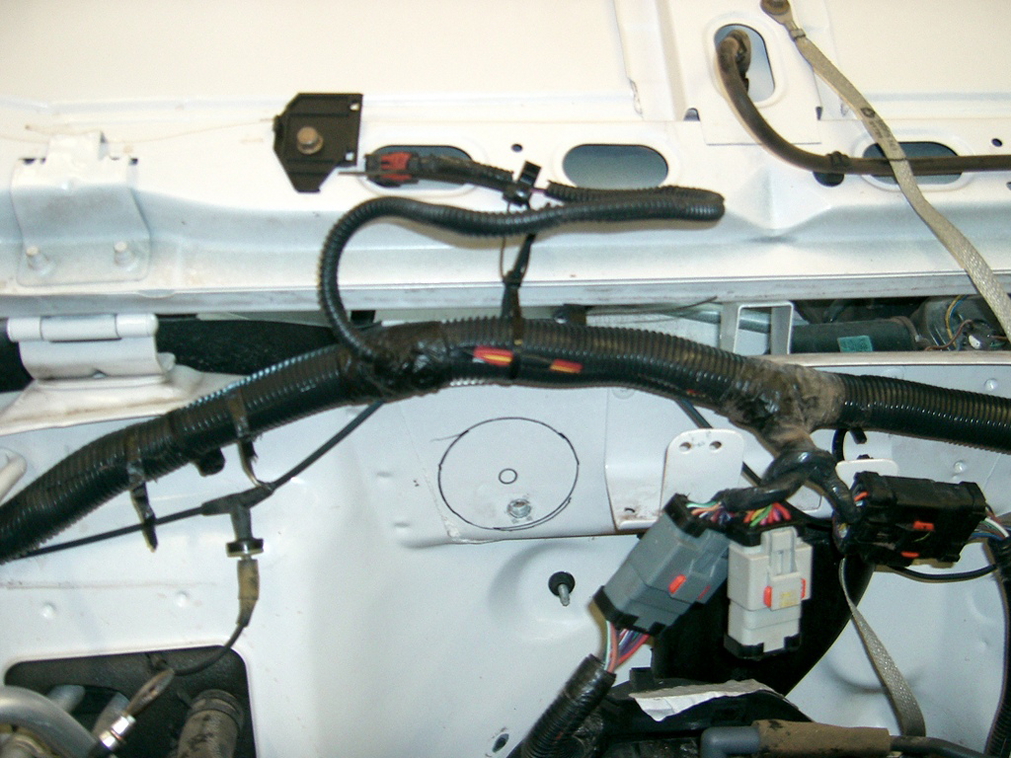
| Remove the computer harness connectors from the bracket on the firewall so that you will have clearance to get to the firewall with the drill. |
 |
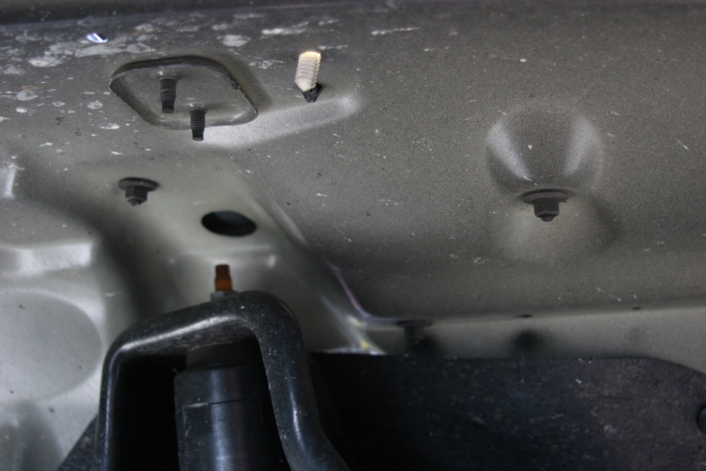
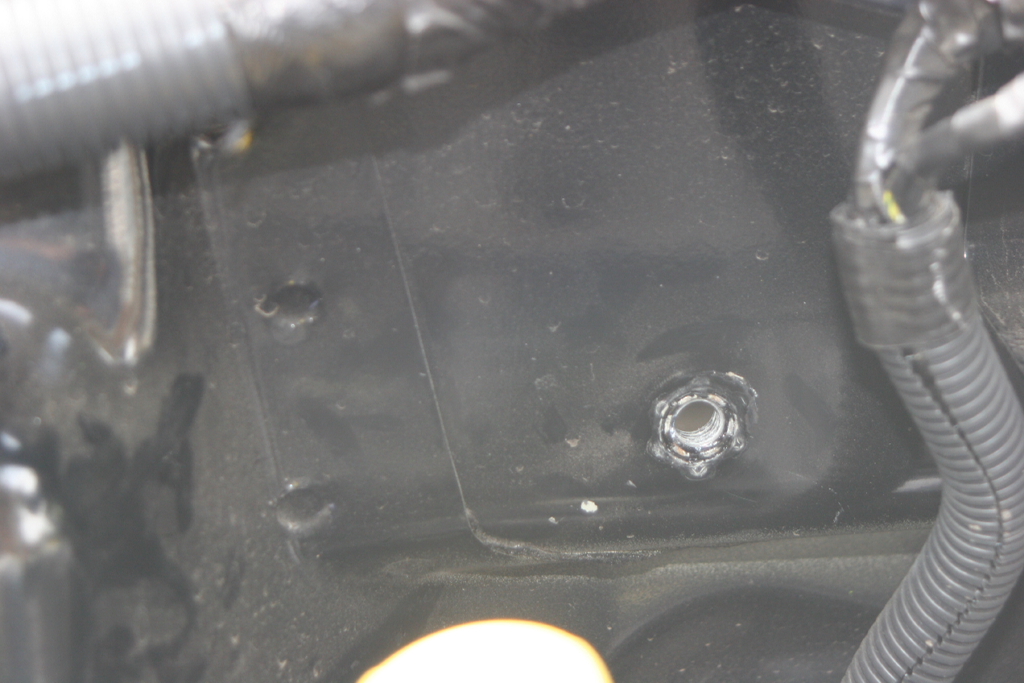
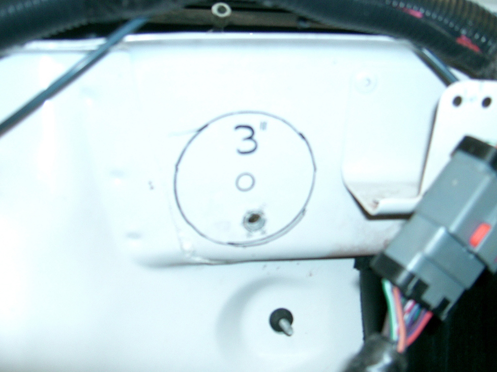
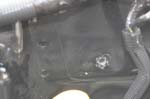
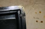
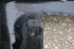
| Mark a point on the firewall. " up from the center of the ground bolt hole, and " to the left. Double check with the 3" hole saw (remove the arbor). The hole saw should just clear the bottom of the welded nut (you should be able to see the tack welds) and not hit the double wall lip on the firewall. |
 |
 |
 |
 |
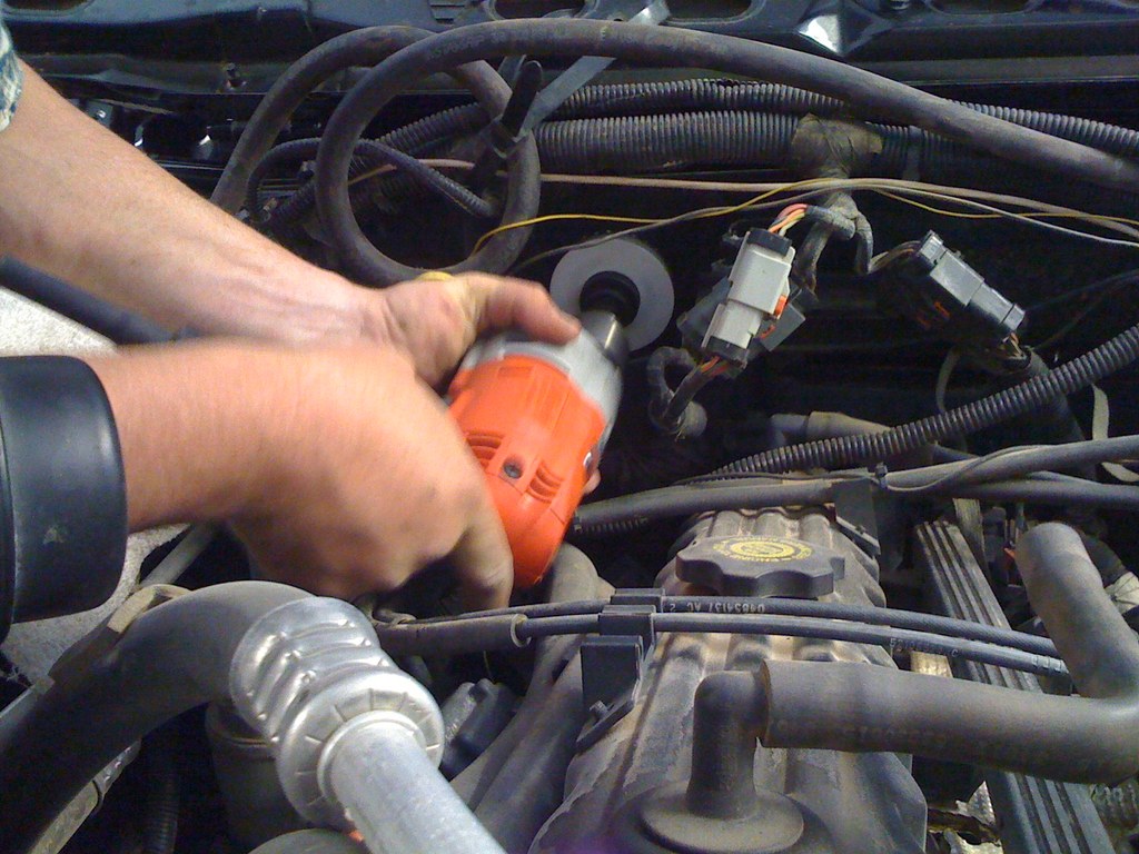
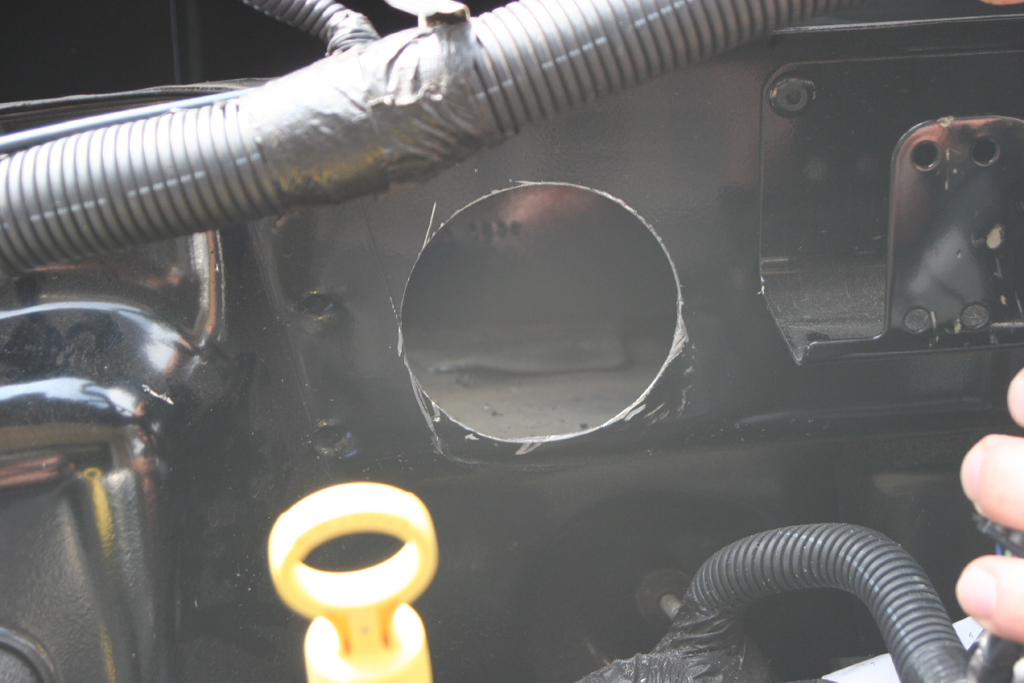
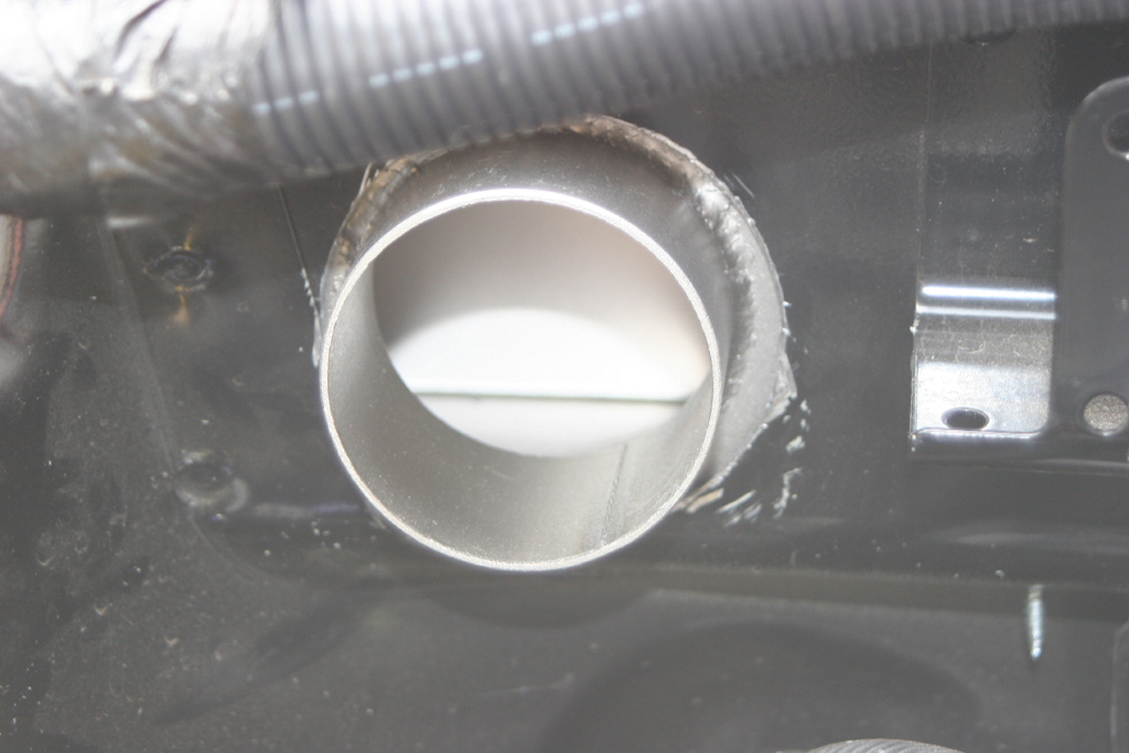
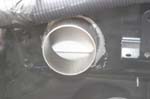
| Drill slowly with the 3" hole saw, it can catch on the metal and yank the drill out of your hands. Ensure that you have a sharp hole saw. |
 |
| The hole in the pictures is drilled low and left to far. It still works, but isn't absolutely perfect. |
|
|
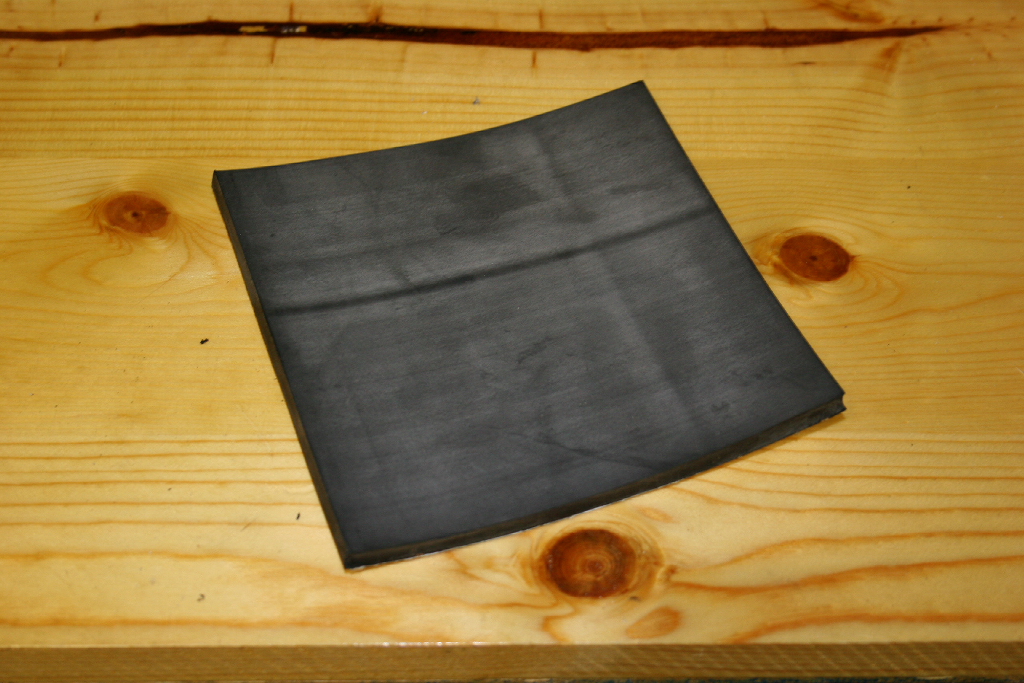
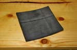
| I used some adhesive rubber sheet to seal the hole around the tube. The kit now comes with a second piece of foam to seal this area. |
 |
 |
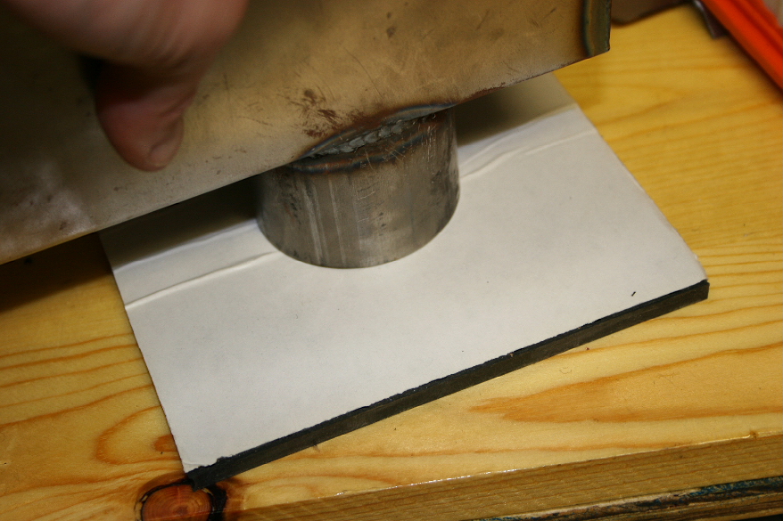
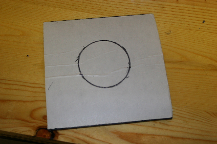
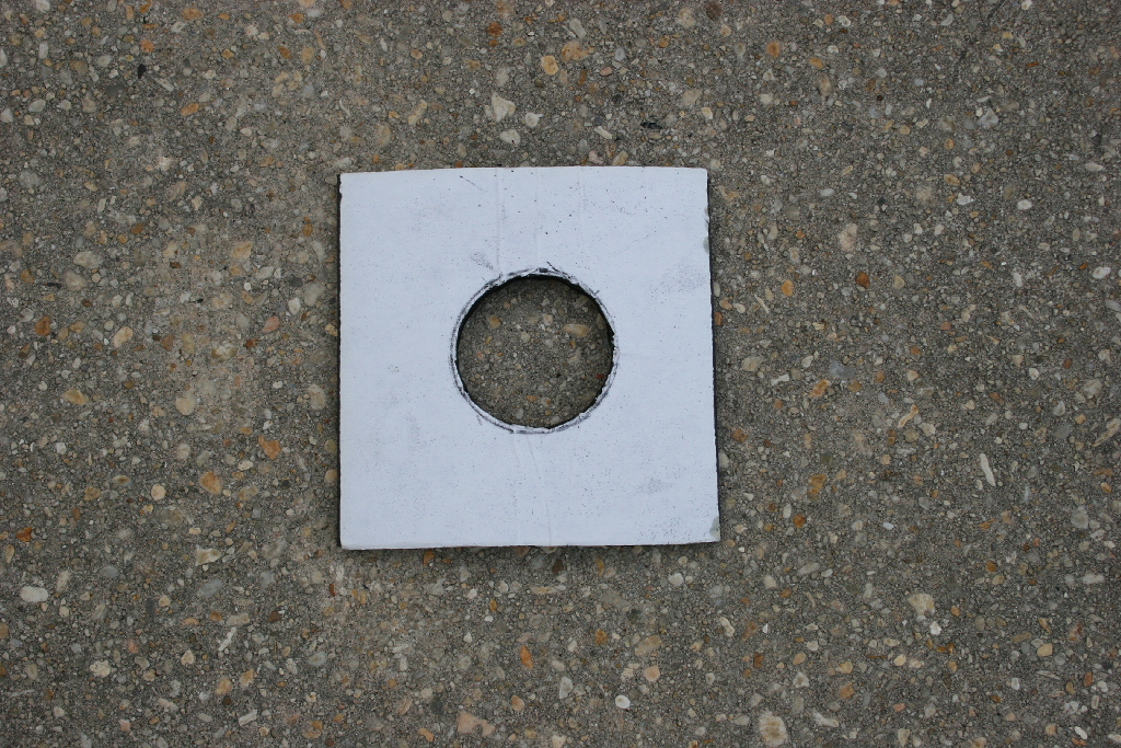
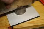
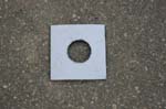
| Mark the back of the rubber sheet using the tube on the baffle as the template. Cut inside the circle. You will need to have the rubber seal against the tube. |
 |
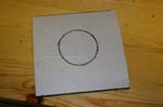 |
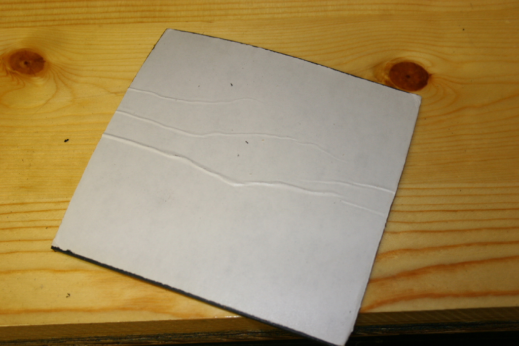
| Mark the back of the foam sheet using the tube on the baffle as the template. |
 |
| Cut inside the circle with a slight bevel so that the foam will seal against the tube. |
 |
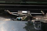
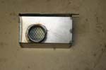
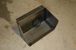
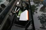
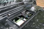
| Insert the air baffle with the tube through the hole. |
 |
 |
 |
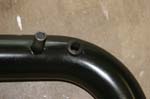
| Center the tube in the hole and secure the air baffle with two self tapping sheet metal screws. |
 |
 |
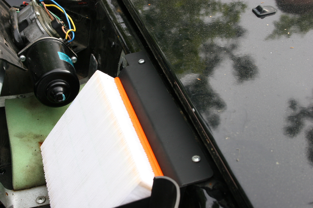
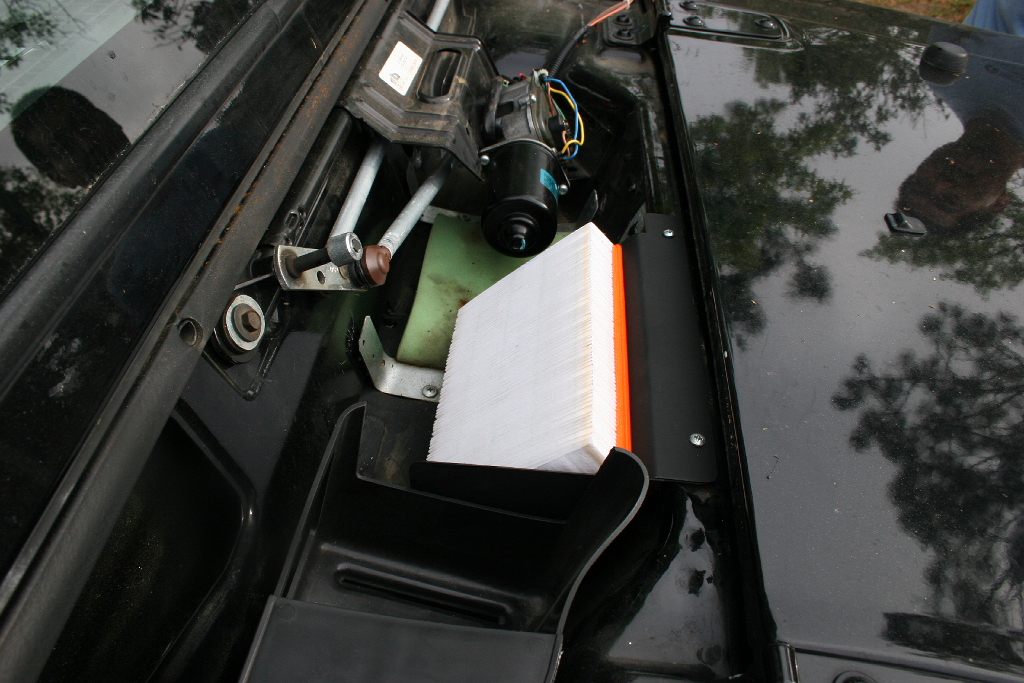
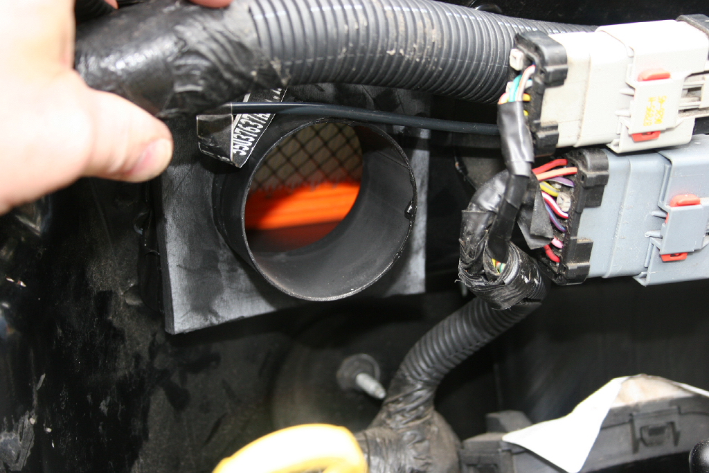
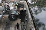
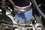
| Install the air filter and hold down bar. |
 |
 |
 |
| I sealed the area around the tube and firewall with some duct seal originally, but on a later install used a piece of adhesive backed rubber gasket material. Not needed if you use the supplied foam. |
 |
 |
 |
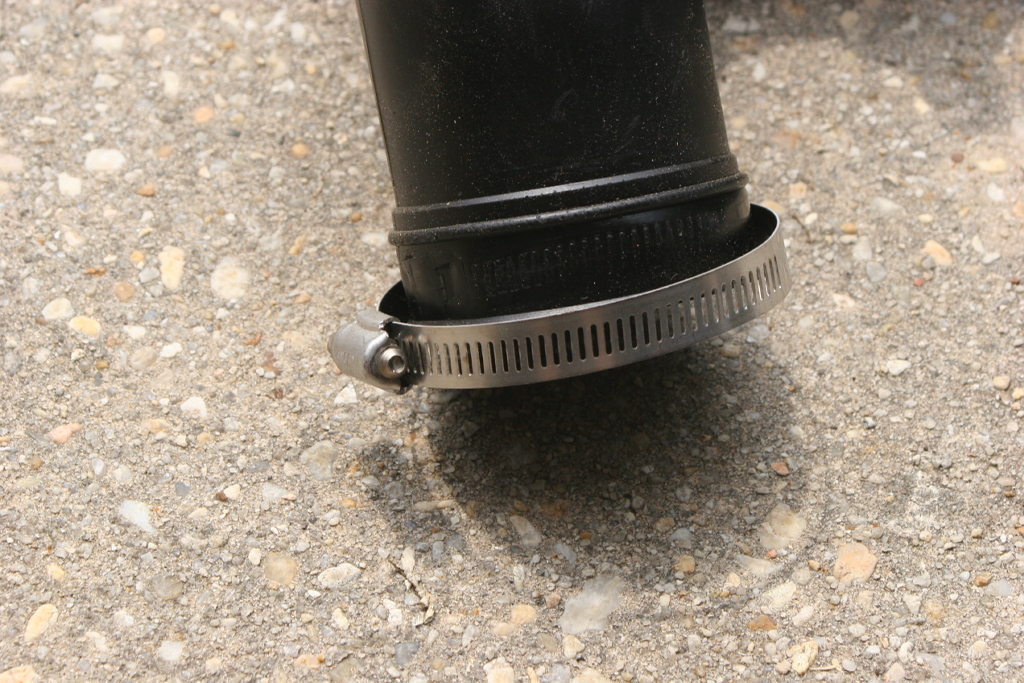
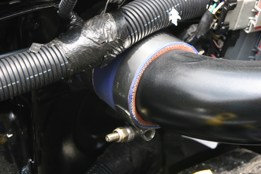
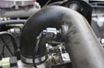
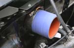
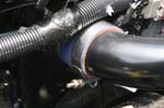
| Install the tube to baffle connector. Tighten the t-bolt clamp with a " socket |
 |
| Reinstall the wiper motor assembly in reverse order of above. |
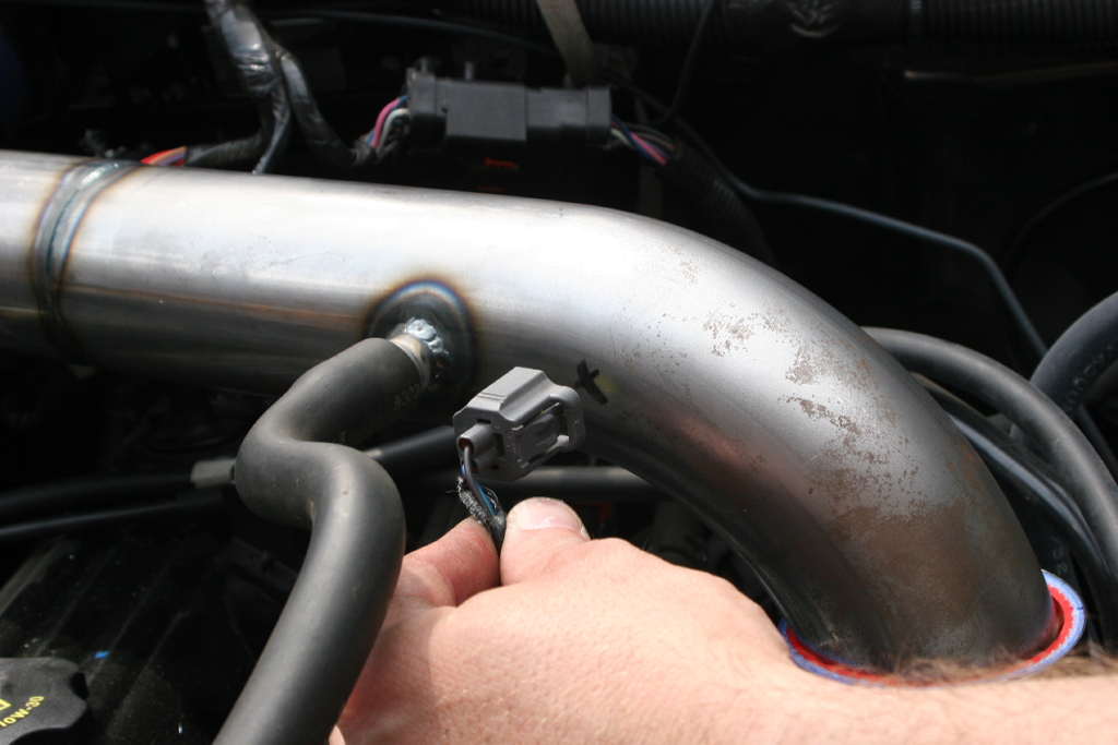
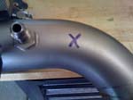
| If you have the IAT sensor located in the air tube (2005-2006 model year), you will need to complete the following steps. Temporarily install the tube to throttle body connector on to the inlet air tube. Install the inlet air tube into the tube to baffle connector and on to the throttle body. |
 |
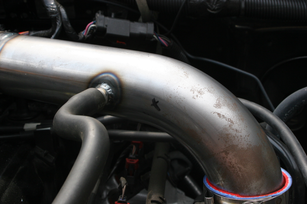
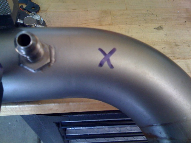
| Hold up the IAT sensor connector to the inlet air tube, and mark an X in the location. This is where you will need to drill to install the grommet for the IAT sensor. Remove the tube. |
 |
 |
 |
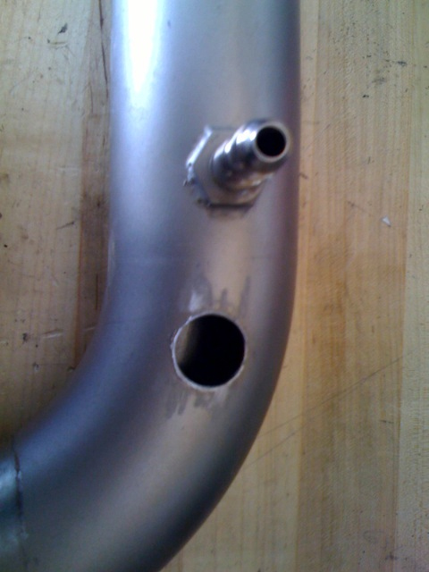
| Using a unibit, drill out the hole to 3/4". You must drill this hole carefully with a sharp bit. We suggest using a Drill Press with the tube in the jaws on the table. Slowly step up on the drill bit size to prevent oblonging the hole in the tube. File smooth. Ensure that there are no metal shavings inside the tube. |
 |
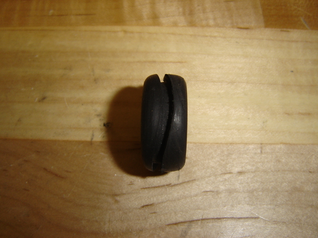
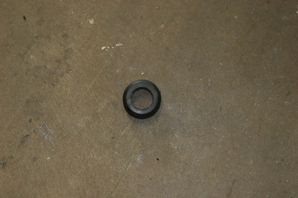
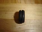
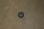
| Insert the grommet into the hole. |
 |
 |
 |
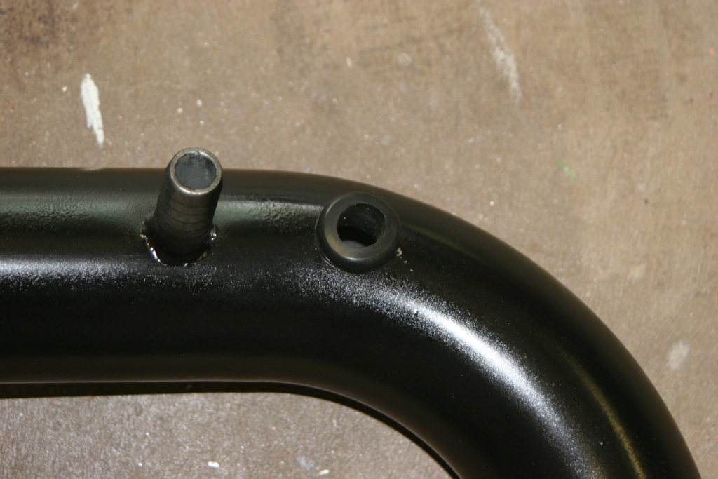
| Install the IAT sensor into the hole until it stops on the tab. |
|
|
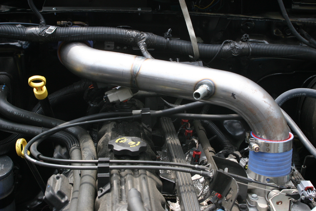
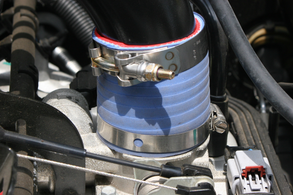
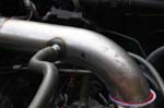
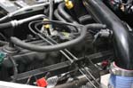
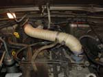
| Reinstall the inlet air tube with the front camp rotated to the bottom. The wire bundle sits close to the top. |
 |
| If you have a 1" Body Lift leave the throttle body to inlet air tube as is. Without a body lift you will need to trim the connector to 3". Tighten all three clamps. |
 |
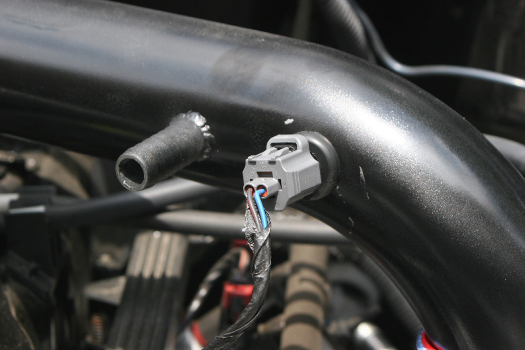
| Install the connector on the IAT sensor. |
 |
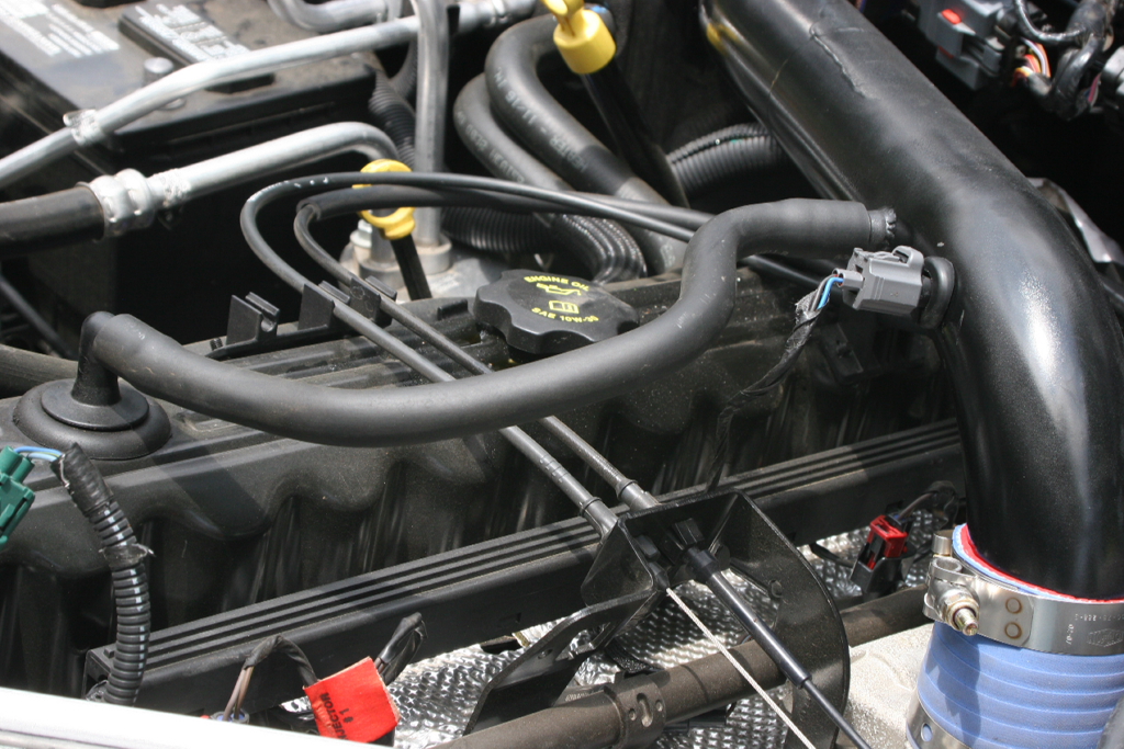
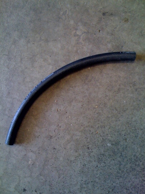
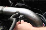
| Connect the valve cover vent line to the inlet air tube. You can reattatch the factory hose by turning it around, or install an new hose cut to length. |
 |
 |
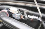
Remount the electrical connectors and cable retainers. You will need to off set the connectors on their mounts.
NOTE: If you can not get the connectors back into the mount, secure them with zip ties. Make sure wires are secure and not touching the metal intake tube. This might cause damage to your wires from excessive heat from the metal tube. |
 |
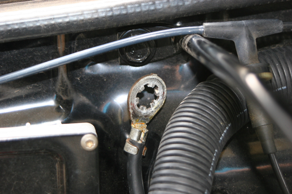
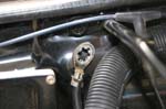
| Remove the passenger side grill support bolt, thread the starter ground up along the firewall and slide under the grill support. Reinstall the bolt with a 13mm socket. |
 |
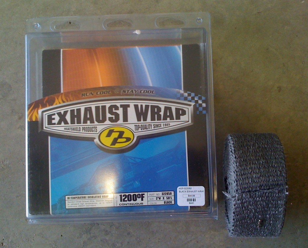
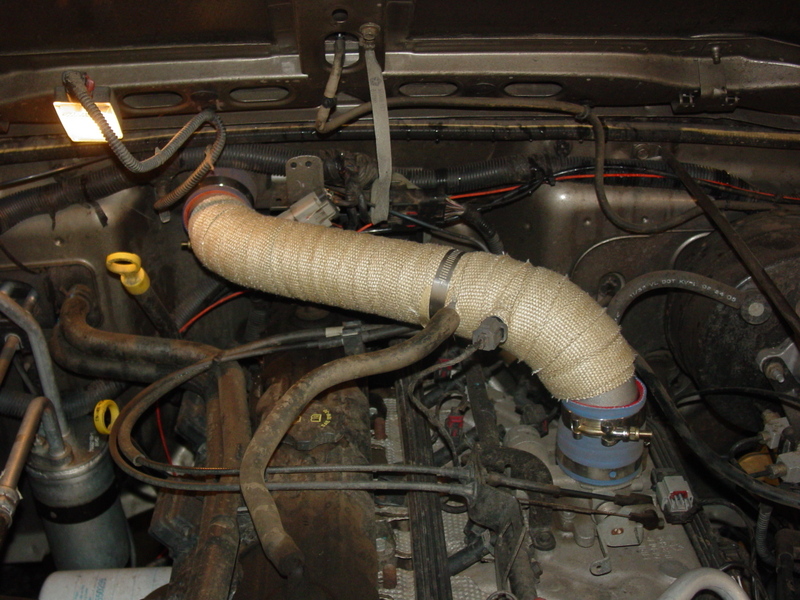
| If you are looking to cool the inlet air further you can wrap the intake tube with muffler wrap to shield it from the engine temperature. |
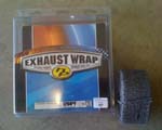 |
 |
| |
| Cabin Air Filter / Cowl Modification: |
| If you are only installing the cabin air filter modification you will only need to complete the following steps after removing the cowl. |
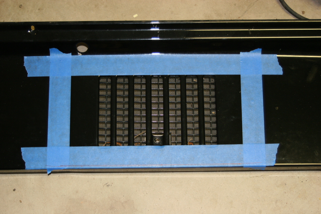
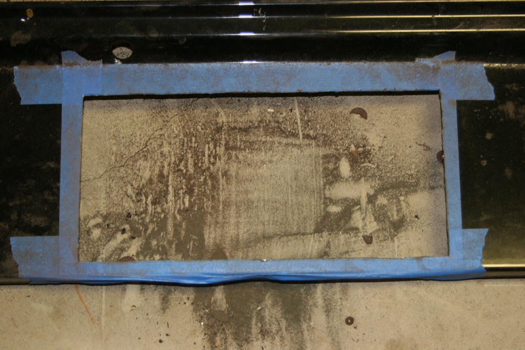
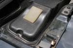
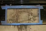
| Tape off the area around the inlet screen on the cowl. |
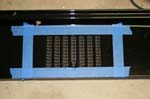 |
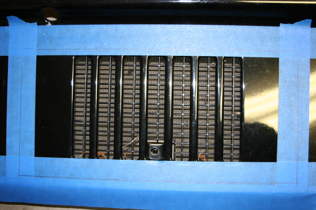
Mark the center of the cowl, and the center of the filter housing. Draw a line 3/8" back from the leading edge of the cowl (Hood side). This is your starting position to line up the side of the filter housing. Place the side of the filter housing on this line and align the center of the filter housing with the center of the cowl. Trace the outline of the filter housing onto the tape.
Note: You should be tracing the outside of the bottom of the filter housing, not the lid. This should be about 13 1/4" x 6 3/16". |
 |
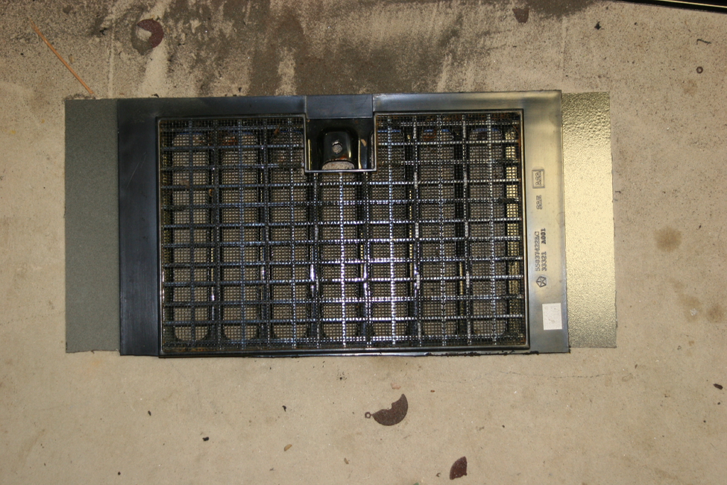
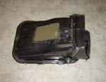
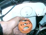
| You can cut through the plastic holding the inlet screen, but we found it easier if you remove the plastic grill by heating up the adheisve with a heat gun or hair dryer (Note: Do not let wife catch you.). |
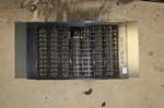 |
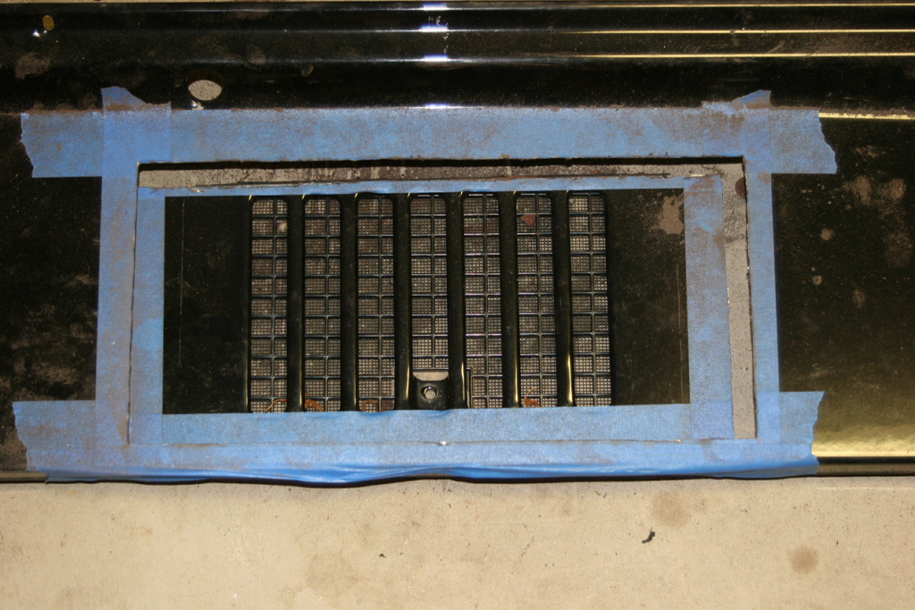
| Carefully cut along the marked lines. |
 |
 |
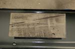 |
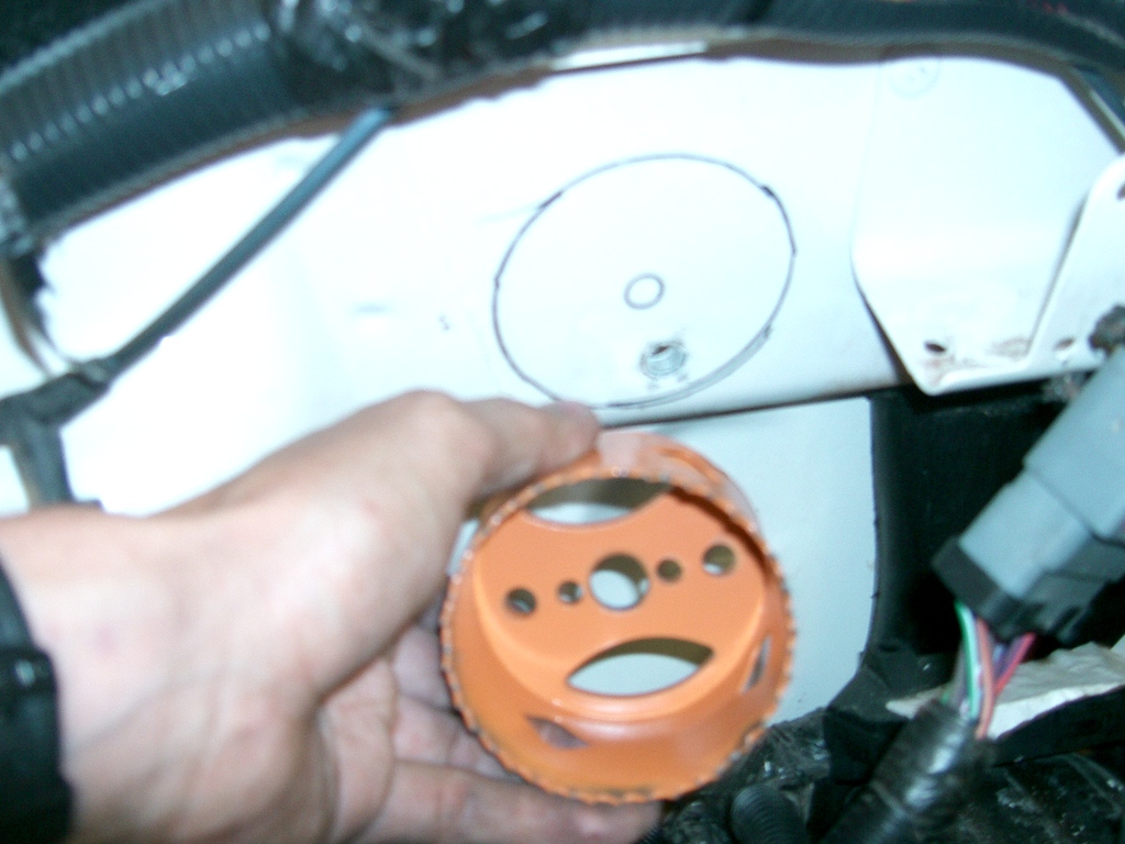
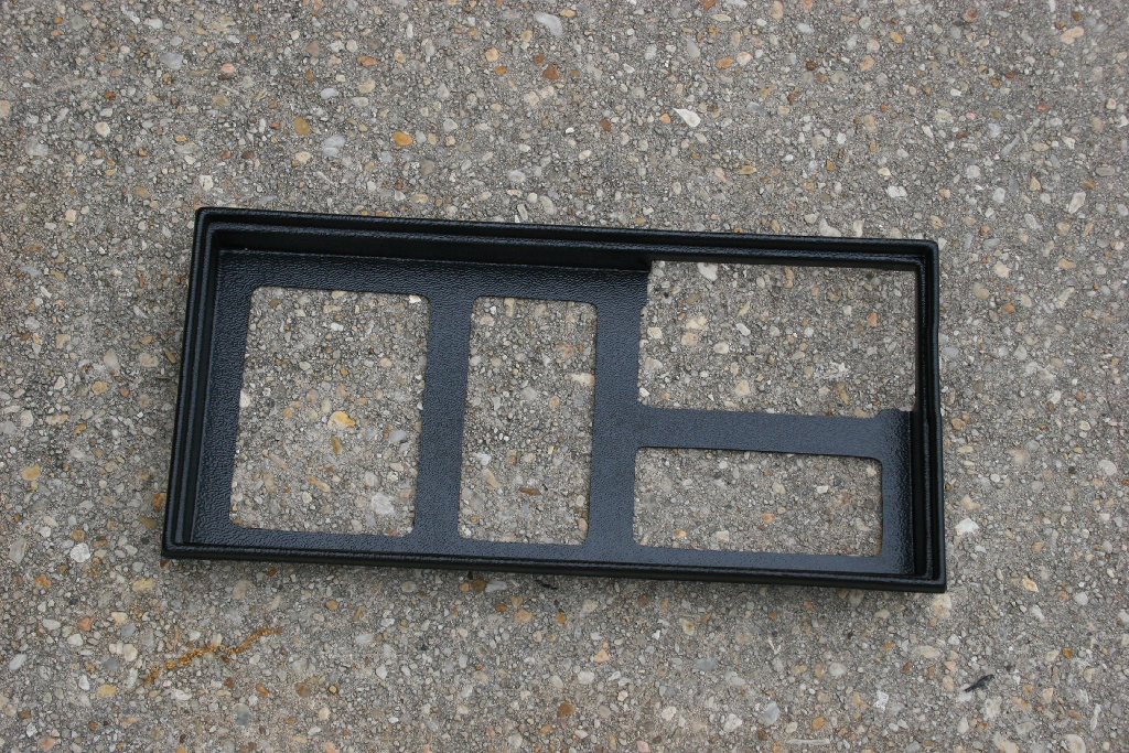
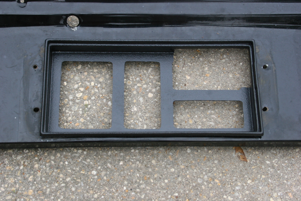
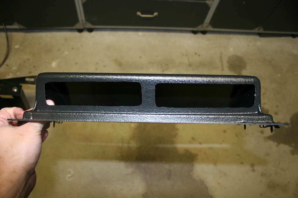
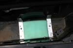
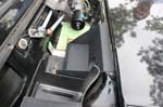
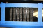
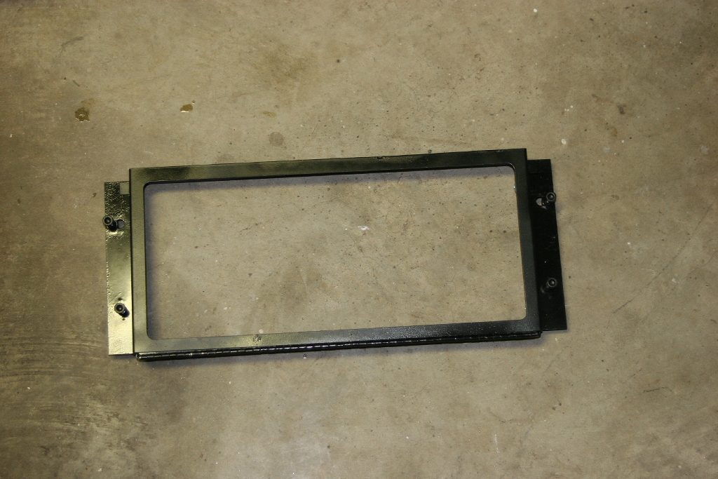
| Test fit the filter housing into the opening. |
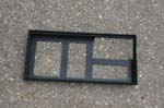 |
 |
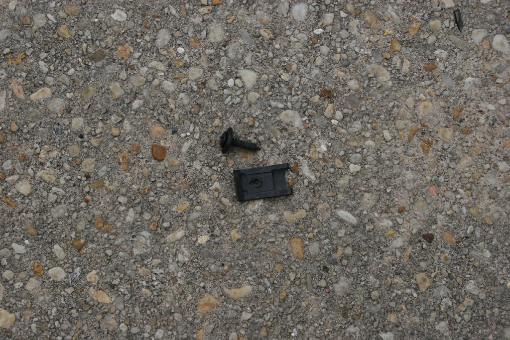
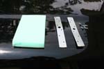
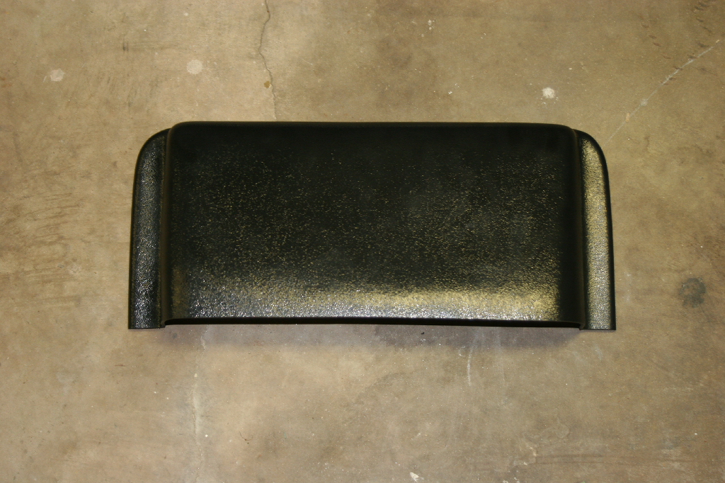
| Remove the screws and clips from the hood scoop. |
|
 |
| Place the scoop over the filter housing (opening towards windshield). |
 |
 |
Mark the pre-drilled holes in the scoop onto the cowl. Remove the insert.
Alternate: Drill the 4 holes with the scoop on the filter insert. Make sure the scoop is aligned with the edge of the cowl and looks square . 2 people are best for this to get the holes drilled while one holds the scoop in place. |
|
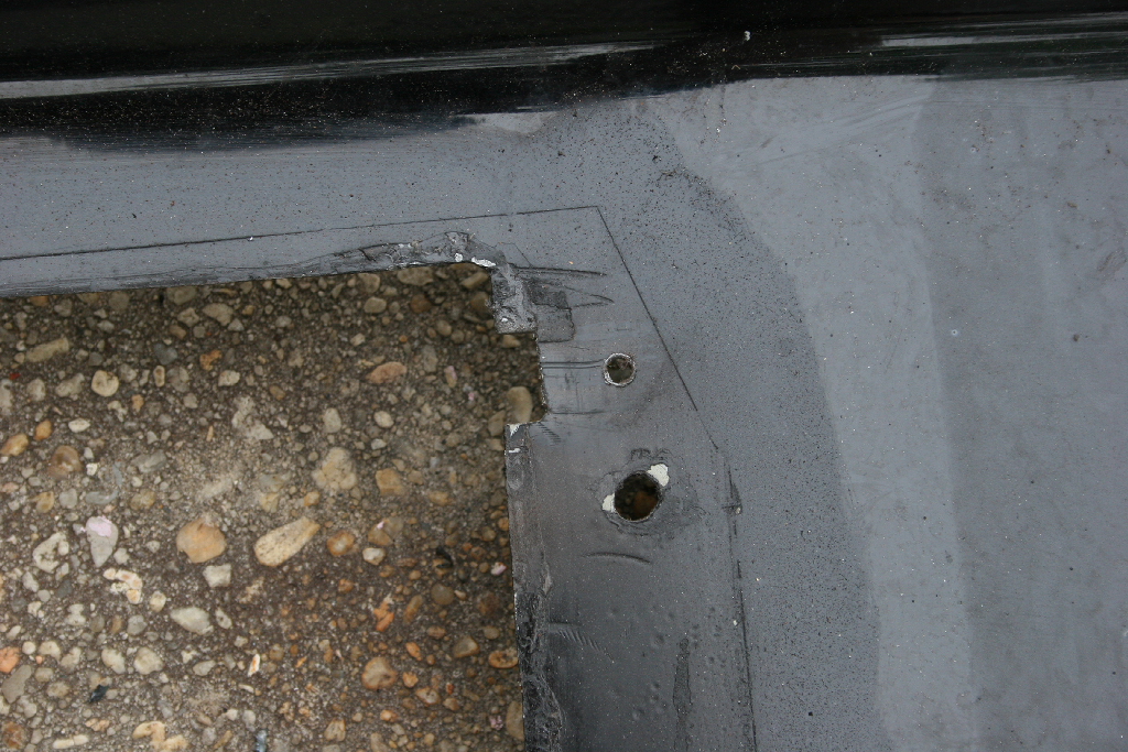
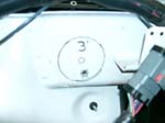
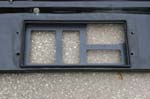
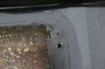
| Drill out the holes for the hood scoop. The second big hole is from the prototype systems scoop. |
 |
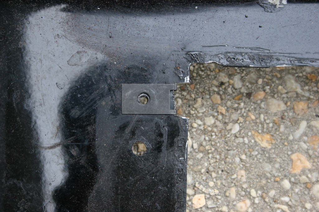
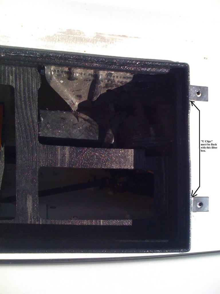
| If required notch either side of the cowl opening to allow the clips to center on the drilled holes. The clips will set flush against the filter housing when installed. |
 |
 |
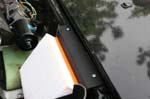
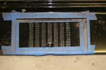
| Clean up the edges and paint to prevent rusting. |
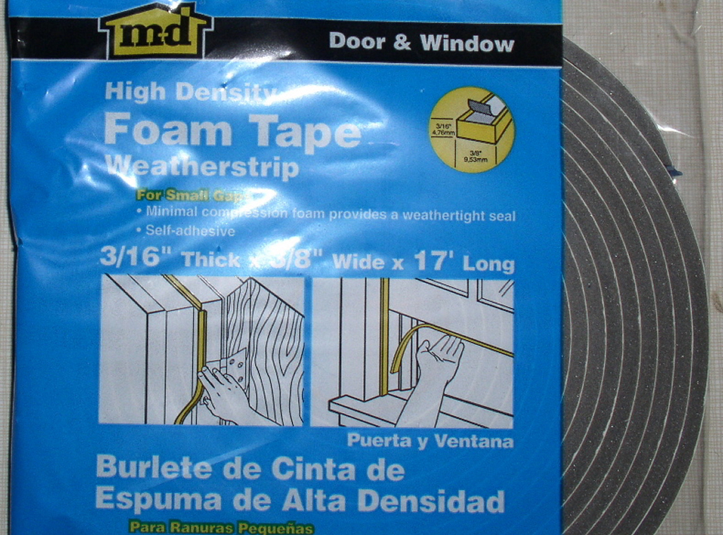
| Seal the edges of the cowl and the windshield hinges with the foam tape. I used some black automotive foam that I picked up at the hardware store. The grey stuff was replaced to look better. |
 |
 |
 |
| Reattach cowl, following the reverse of the removal steps. |
| You may run into a problem with the electrical connector on the wiper motor hitting the filter housing. |
 |
| If you do, just pull the connector from it's bracket and move it out of the way and zip tie to the bracket in front of the motor. |
 |
 |
| Reinstall the weather stripping on the leading edge of the firewall. |
 |
 |
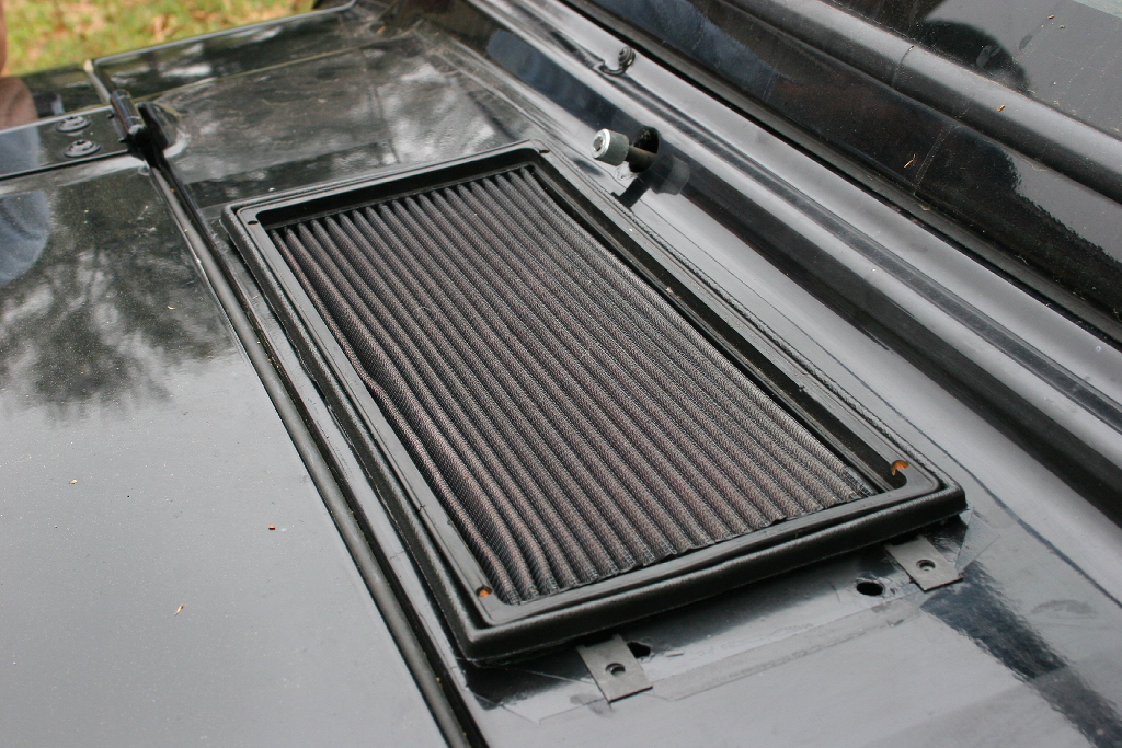
| Reinstall the filter housing. You can run a tiny bead of silicone underneath the lip of the filter to seal the filter edge. Do not forget to install the clips before you do this. It makes a mess removing the insert later. |
 |
 |
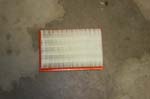
| Install air filter in the filter housing. |
 |
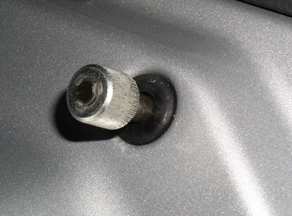
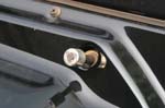
| Insert the 2 other grommets over the windshield wiper mounts and into the cowl. These will help seal the windshield wipers. |
 |
| Reinstall the windshield wipers in reverse of removal. |
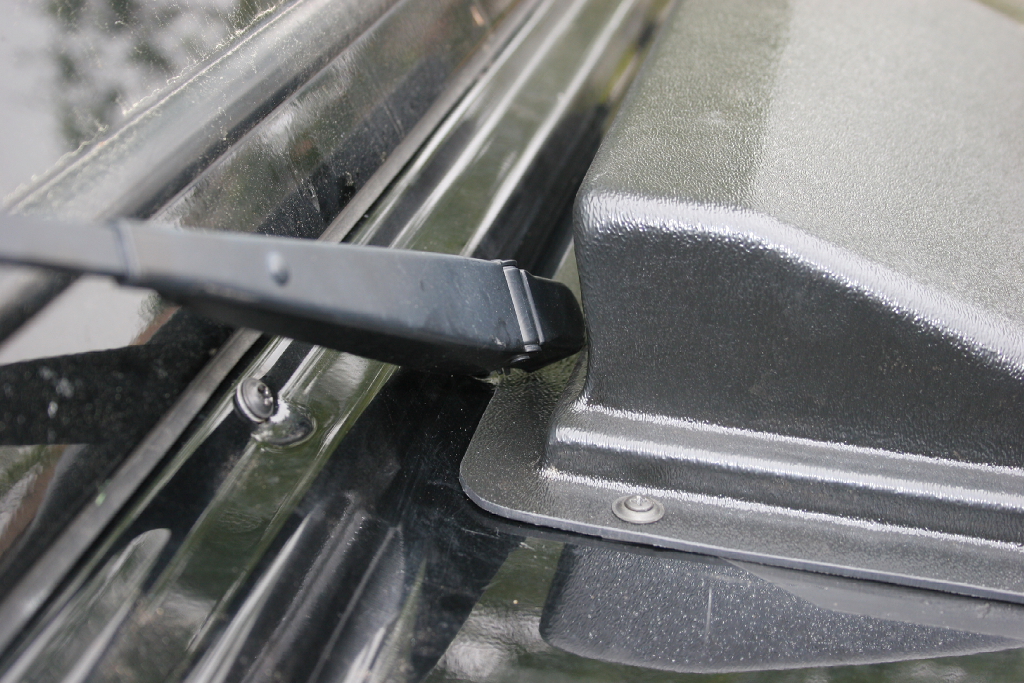
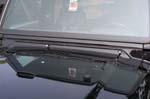
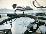
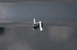
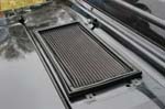
| Slide the scoop lip underneath the windshield wiper and screw down to the cowl. |
 |
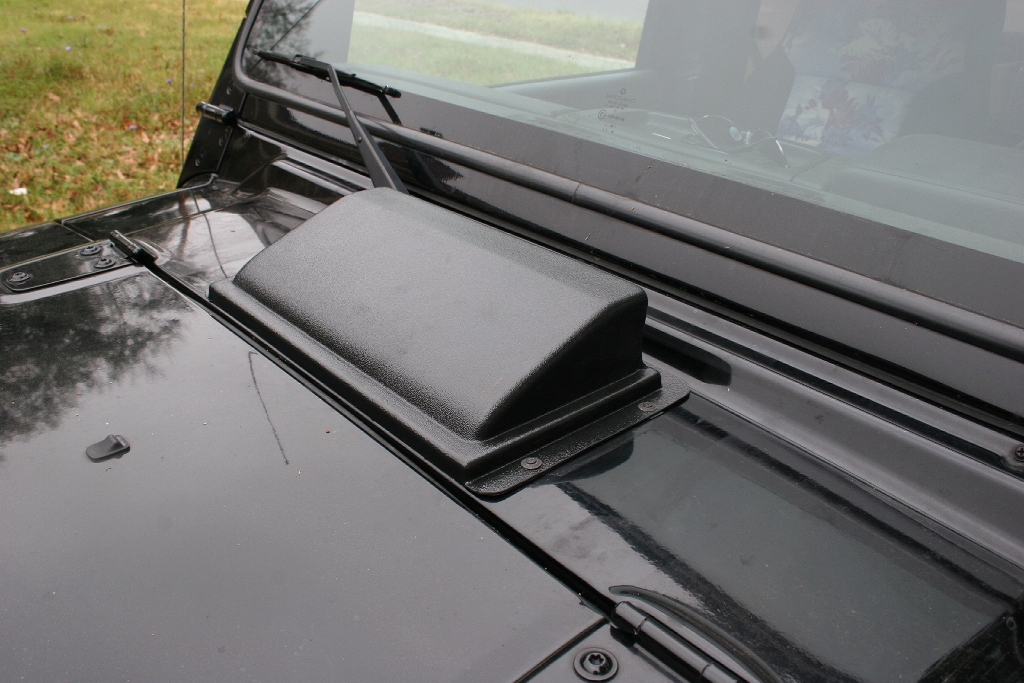
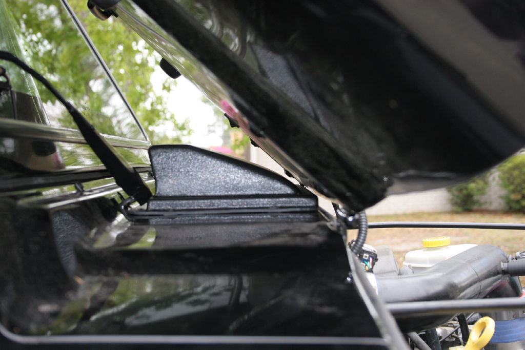
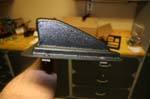
| Installed scoop. |
 |
 |
This write up is not complete. If you find any issues please get back to Mac on them. I am obviously missing a few notes on tools and drill bit sizes, along with some pictures that I will hopefully correct in the future.


