After AiROCK I decided to try out the Clayton 4.5" lift. Nothing to hard about this lift with the exception of a little bit of grinding on the front axles and having to cut off the bolt on the passenger side upper control arm to get it out. I did net nearly 6" of lift out of this kit and this is with the river raider skids, and heavy bumpers on the Jeep. On second thought I probably should have gotten the 3.5" springs. You will have to excuse the lack of some pictures, I lost a bunch when the computer crashed.
The Clayton 3.5" kit is intended to fit 35x12.5 tires, and the 4.5" kit is intended tofit 37x12.5 tires. Stock rim backspacing will not work. You will need either a 1.5" spacer, or a rim with a backspacing of 4.5". It may be necessary to install a CV drive shaft on the front for either the 2 or 4 door models. You may also need a CV driveshaft for the rear on the 2 door models.
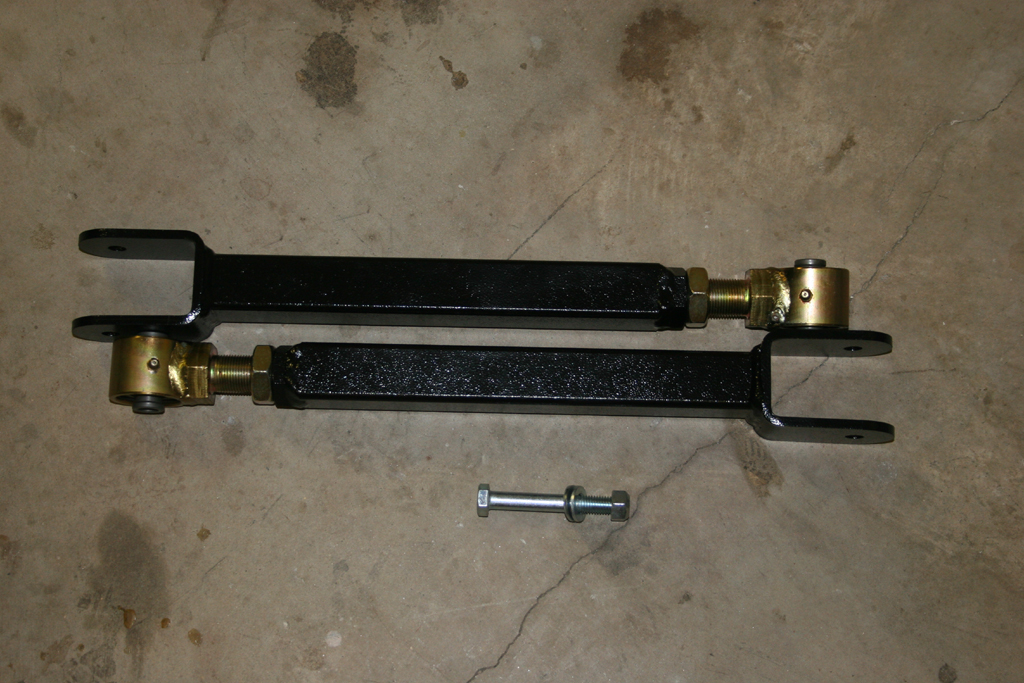
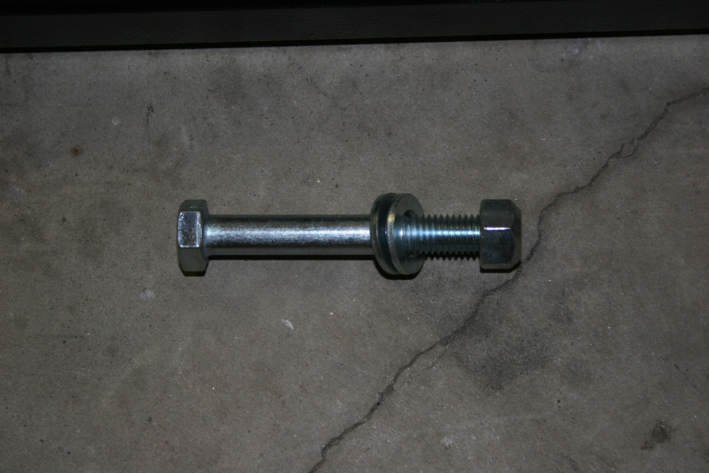
| Sort out your suspension lift parts: |
| Now is a good time to sort out all the suspension part to ensure the you have the nuts and bolts that belong with each part. I usually put them together to keep them in place. Example would be putting the bolt and nut that belong with a bump stop through the bump stop and putting it aside. A few times I have gotten into a project only to discover a missing bolt or part. Better to double check before than to get things torn apart and have to put them back together because you didn't have the right or all parts. |
| |
| Preparing the Suspension: |
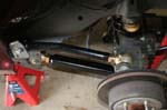
| Most of us will be doing this on the garage floor and won't have the luxury of a lift and axle jacks, so we will work on one section at a time. Blocking the tires that remain on the ground is important to keep the Jeep from rolling. Having a good set of floor Jacks to support the Jeep. I use a set of 6 ton jacks to hold the Jeep up. You will need to loosen and remove a few bolts prior to starting the real hard work. Like always if in doubt as to safety, or your abilities, get help, or take it to a reputable shop. |
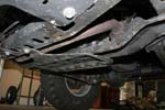
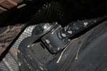
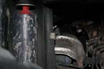
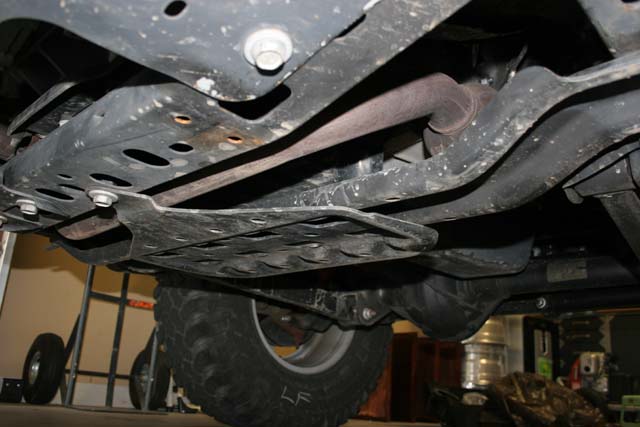
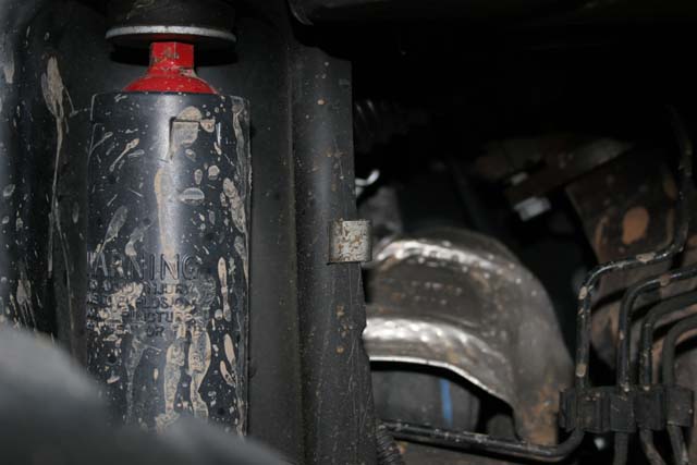
| If you have an automatic you will need to remove the front skid plate. The skid plate will come in contact with the front driveshaft during articulation. |
 |
| |
| Front Suspension: |
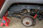
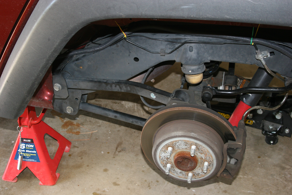
| 1. Jack up the front suspension and support the Jeep with Jack Stands behind the lower control arm. Remove the tires. Leave the floor jack under the axle to relieve some pressure on the bolts for the next couple of steps. |
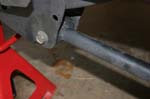
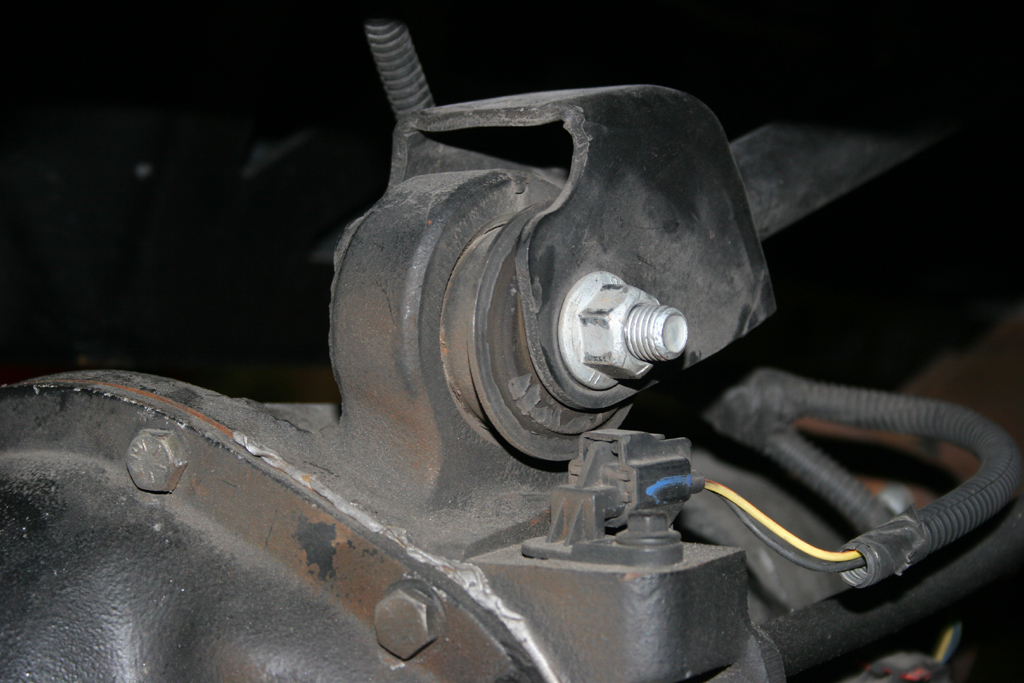
| 2. Loosen the following bolts: Upper control arms and lower control arms. You will need a 18mm and 21mm Sockets and combo wrenches. |
 |
 |
 |
 |
| 3. Remove the following bolts/nuts: |
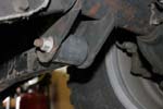
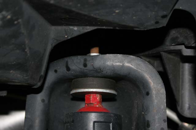
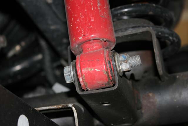
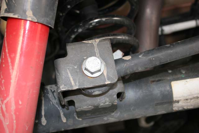
Lower shock bolts, upper shock nut. You will need a 18mm socket and combo wrench for the bottom and a 16mm combo wrench for the top. Jeep provided a second nut below the top one to get ahold of with another 16mm open end wrench to get the top loose. I recommend using a ratcheting wrench to unscrew the top.
|
 |
 |
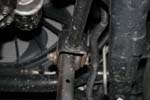
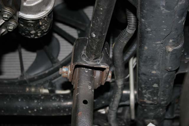
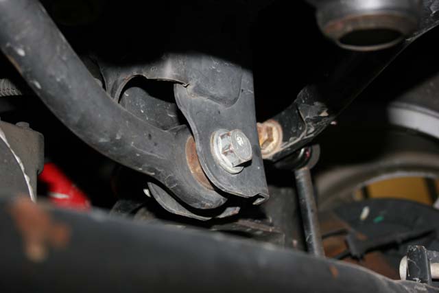
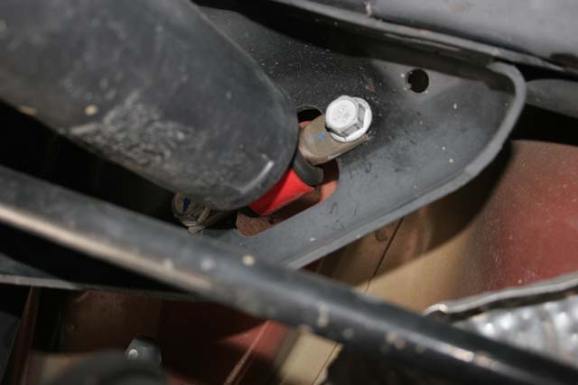
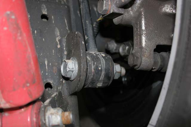
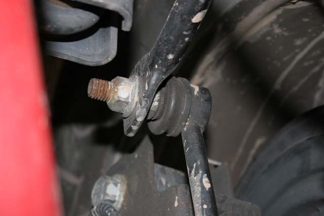
Front anti-sway bar lower bolt, front anti-sway bar upper nut. You will need a 19mm combo wrench, 18mm combo wrench, and 18mm socket.
|
 |
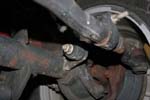 |
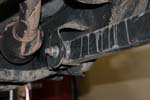
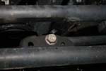
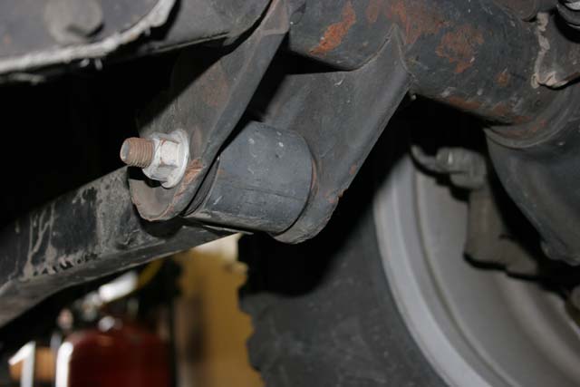
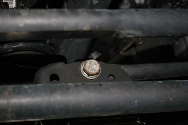
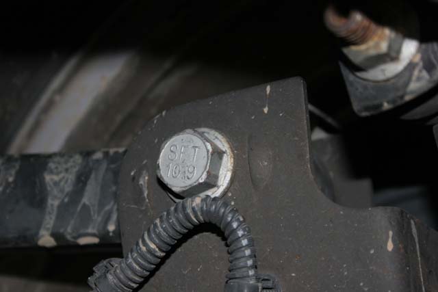
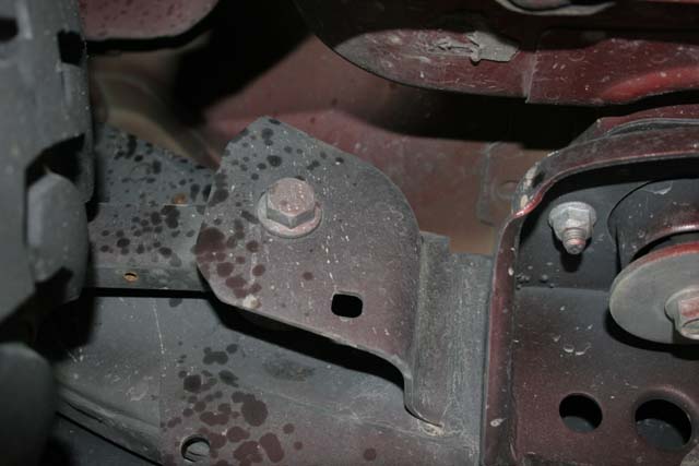
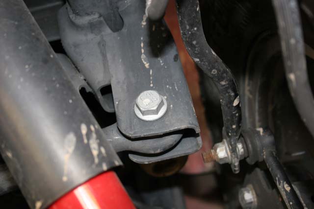
Front trackbar upper bolt, front trackbar lower bolt. You will need a 21mm combo wrench and socket
|
 |
 |
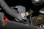
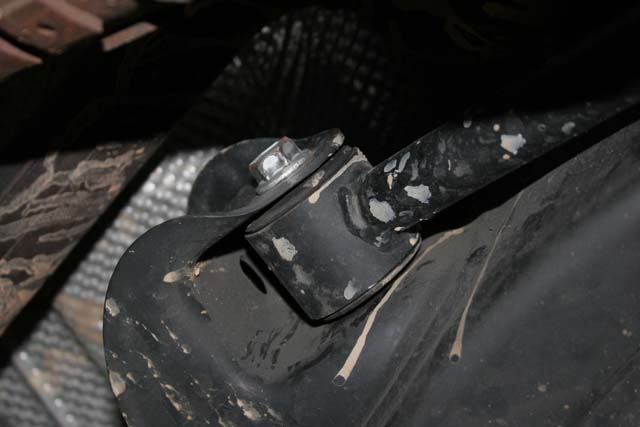
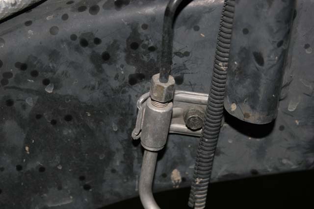
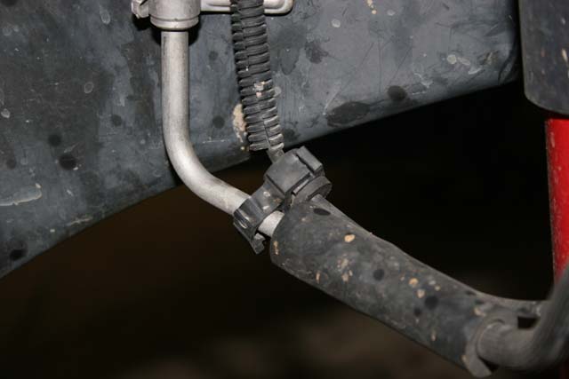
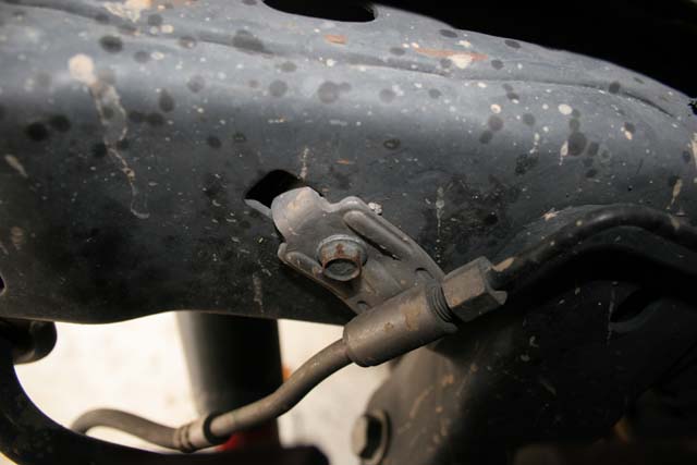
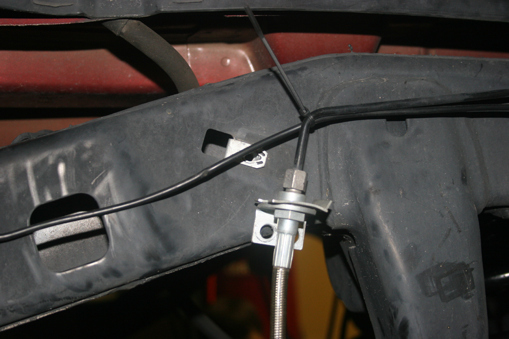
Brake line mount to frame. You will need a 10mm socket.
|
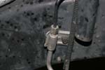 |
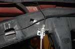
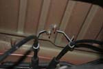
| 4. Unclip the speed sensor cables from their brackets on each wheel hub. You will need the extra slack. For Rubicon models, you may need to unclip the front locker cable to the differential. |
 |
 |
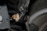
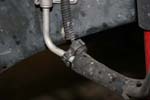
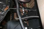
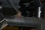
| 5. Move the clip holding the front axle breather down about 4 inches. The clip is located on the driverside shock tower. |
 |
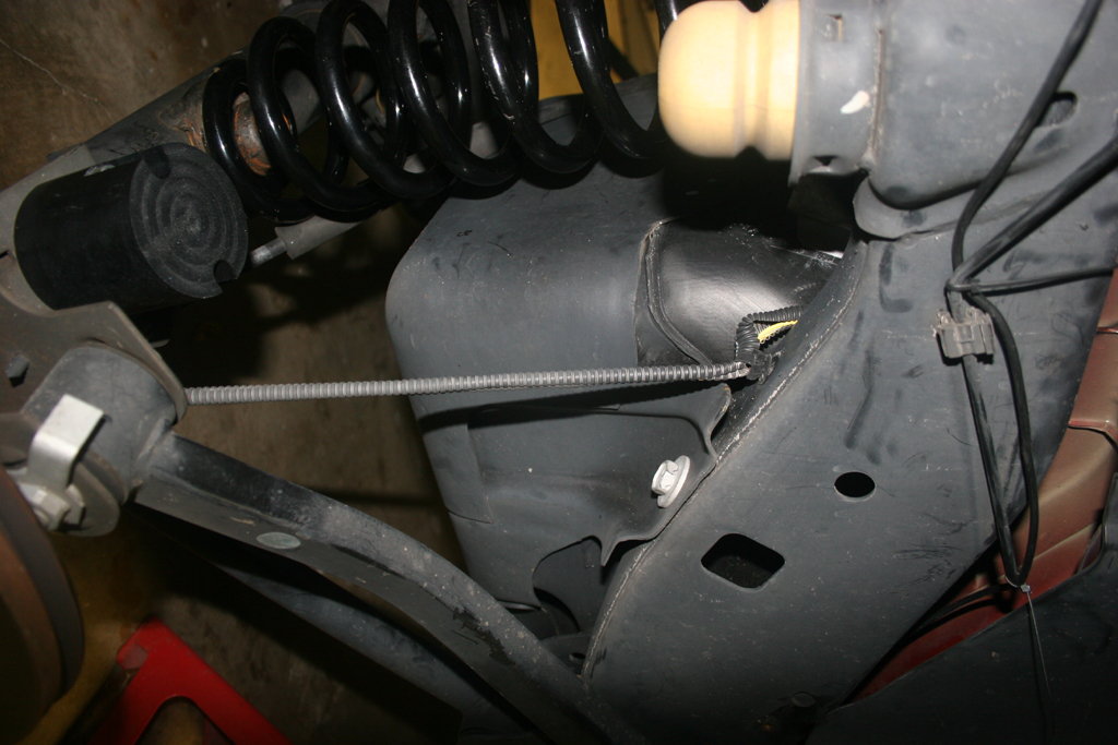
| 6 . Slowly lower the axle down towards the ground. Watch the brake lines, speed sensor lines and the locker cable on the differential. |
|
|
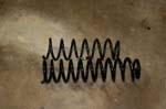
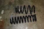
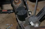
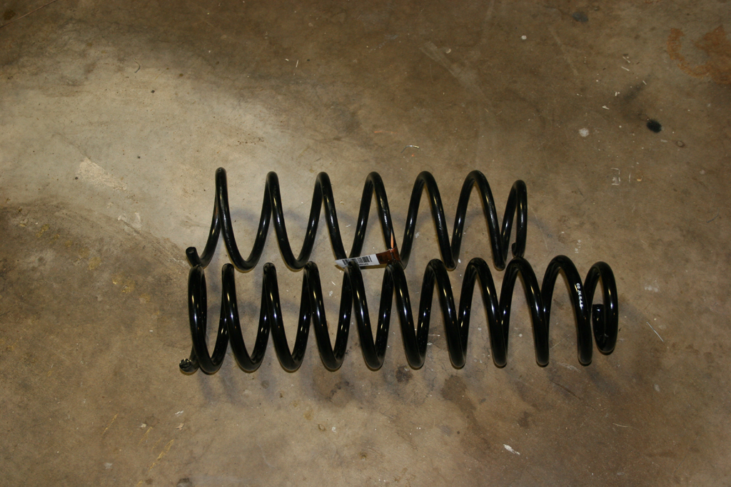
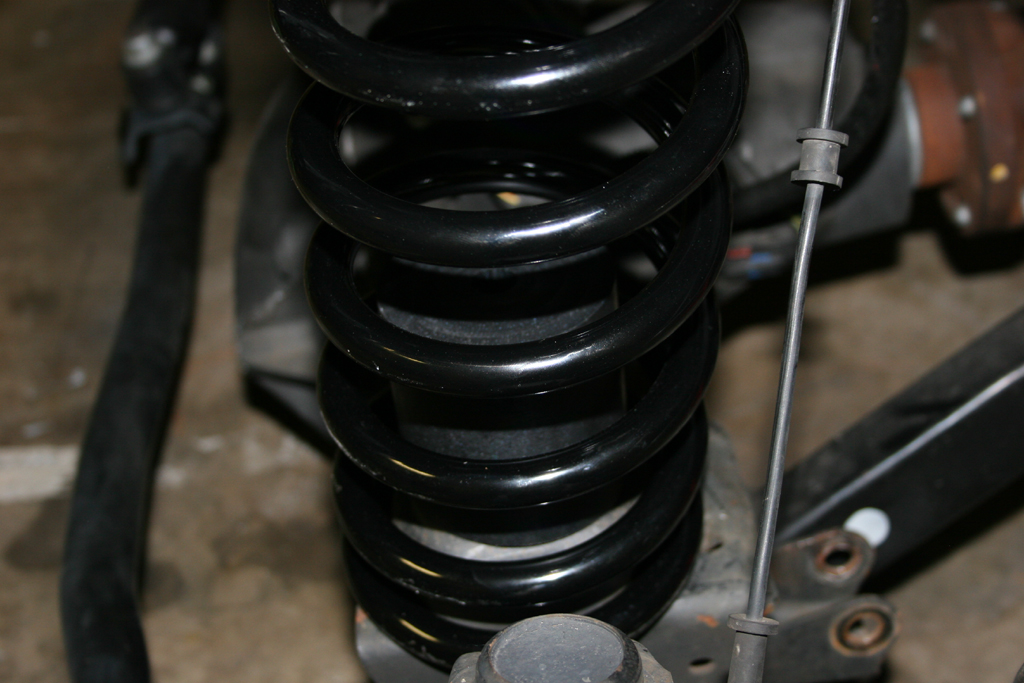
| 7. Remove your front springs. They should just pull right out. |
|
|
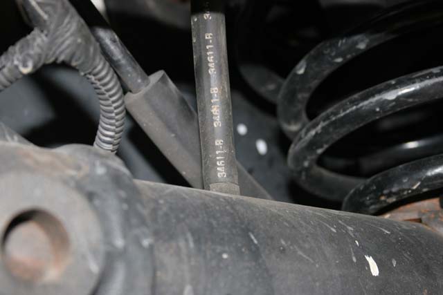
| 7a. Quick comparison shot. |
 |
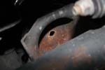
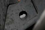
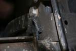
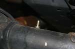
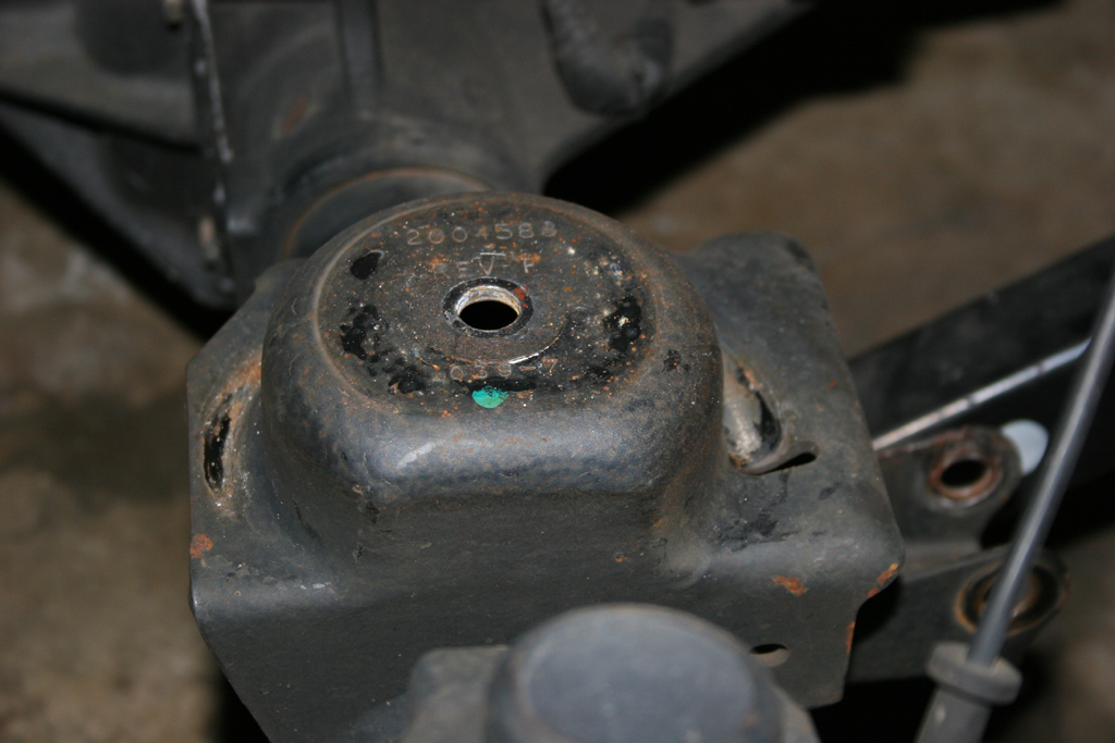
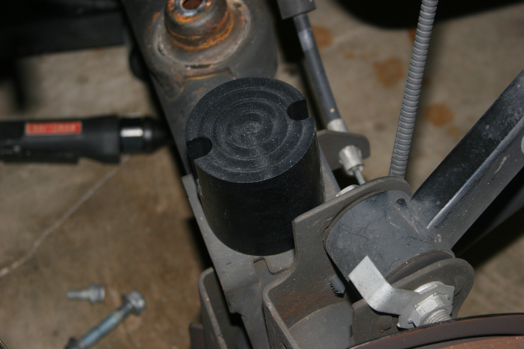
| 8. Drill a 3/8" hole centered in the front spring bad. This will be for the bump stops. Touch up the hole with some paint to prevent rusting. Alternately you can drill a 5/16" hole and tap it to 3/8"-16 with a tap. I tapped one side, and drilled the other, didn't see any difference long term. |
 |
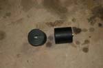
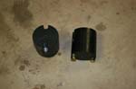
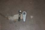
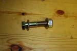
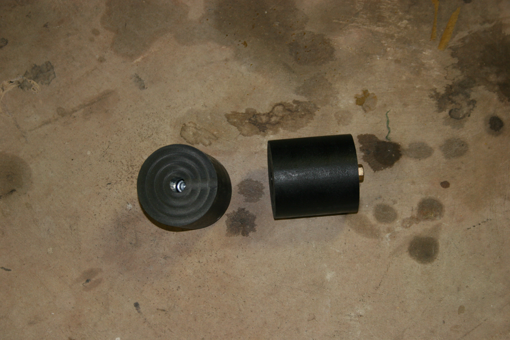
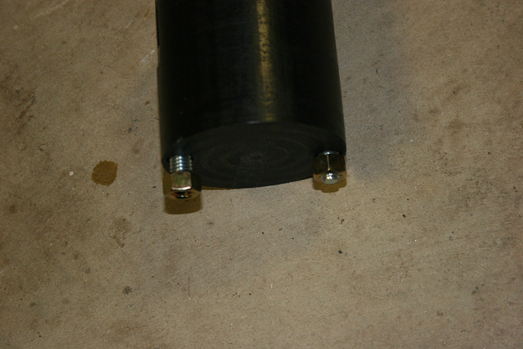
| 8a. This is what the bump stops with the screws look like. The nut will go up inside the spring pad from the bottom. |
 |
 |
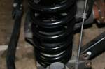
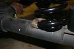
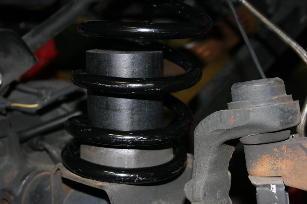
| 9. Lift the Clayton spring up around the upper bump stop, slide the clayton bump stop up into the spring (small hole down) and push the spring over the lower spring mount. A large flat screwdriver can help wedge the spring up and over. A few other ways are jacking up the opposite end of the axle, using a spring compressor, or a large friend standing on one end of the axle. |
 |
 |
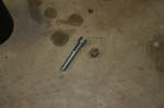
| 10. Insert the bolt through the bumpstop and into the spring pad. Thread the nut onto the bolt, and tighten down. You will need a 5/16 " allen wrench and a 9/16 " combo wrench. |
 |
 |
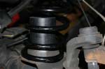
| 11. Make sure you index the spring into the notch on the spring pad. |
 |
12. Repeat the steps for the opposite side. You will need to jack up the side you just did to assist in getting the springs in on this side.
Note: Be careful you do not lift the Jeep off of the Jack stands and release the pressure to fast afterwards. |
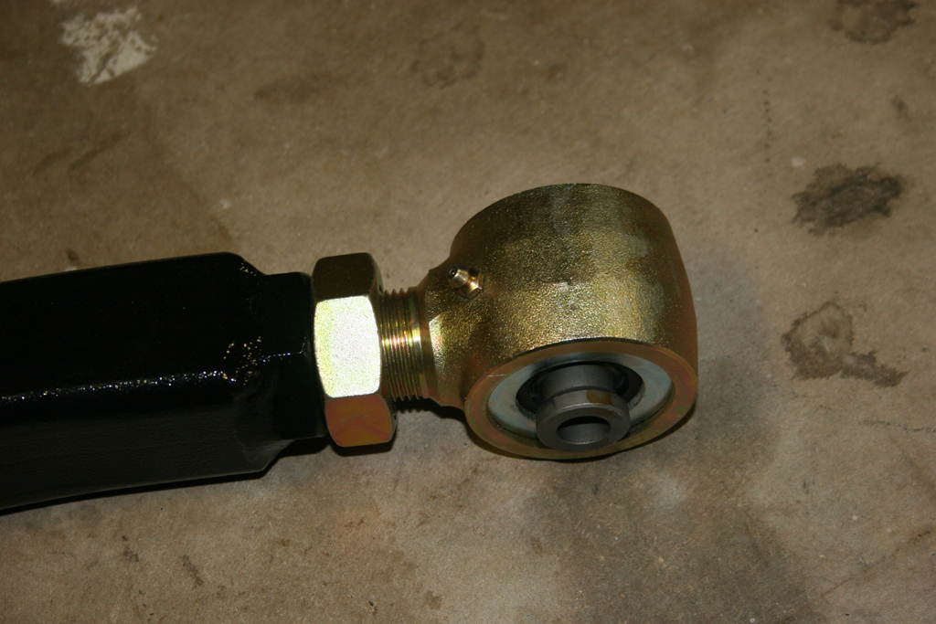
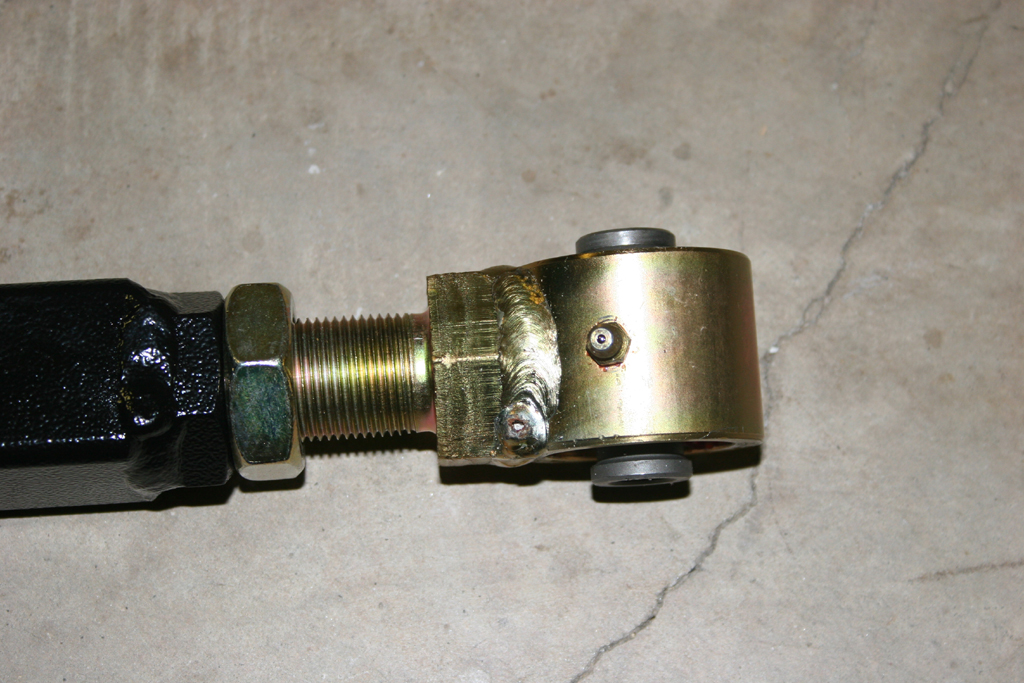
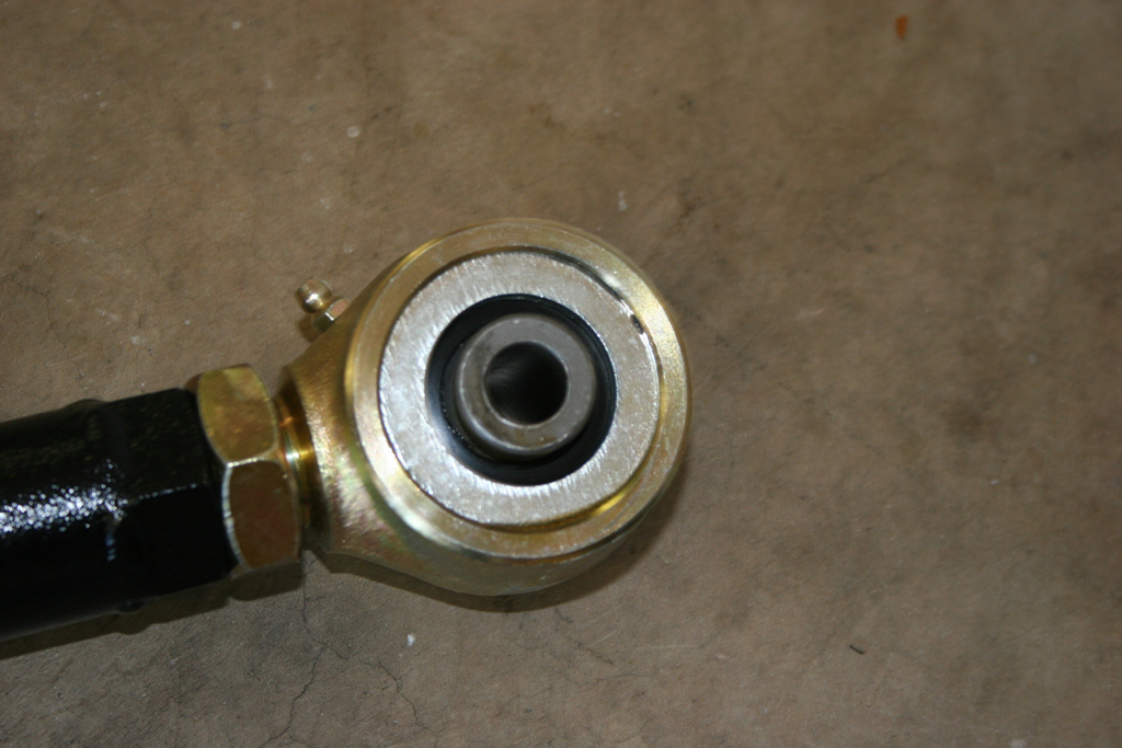
| 13. Find the lower control arms and install the zerk fittings.Do not overtighten the zerk fittings, you will snap them off. You will need a 5/16" combo wrench or socket. |
 |
 |
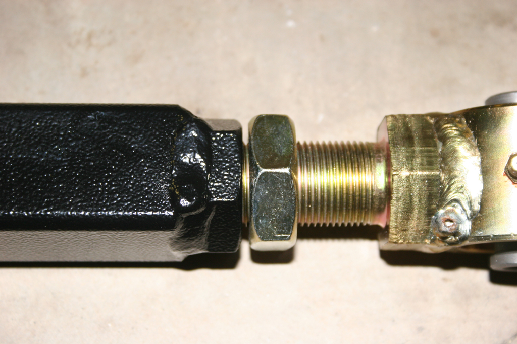
| 14. Adjust the lower control arms to 23 inches in length. Snug up the jam nut, we will tighten it once the arm is installed. |
 |
| 15. With the suspension lowered. Remove the lower control arms. You will need a 21mm socket and combo wrench. |
 |
 |
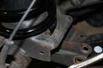
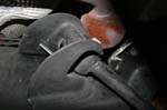
| 16. Grind out the lower control arm mount on the axle. You will need to do this to allow the square tubing of the clayton arm to articulate. You now have more suspension travel and without grinding out the bracket you will be limited by the control arm making contact. |
|
|
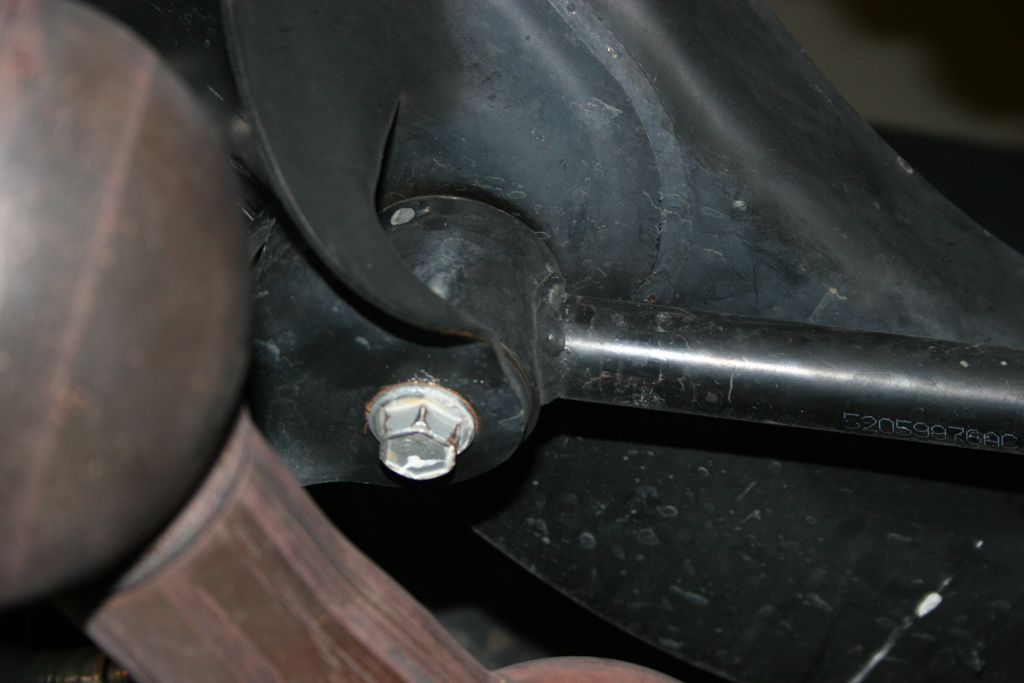
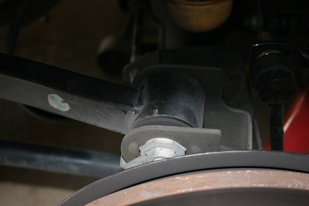
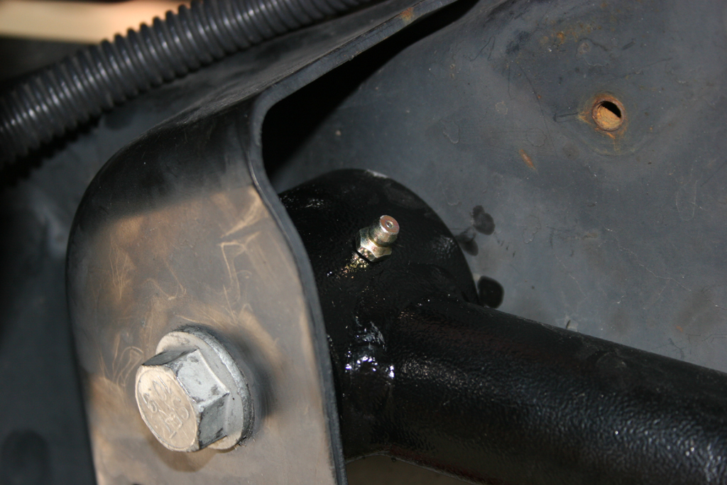
| 17. Install the Lower control arms. Reuse the factory hardware. Do not tighten yet, just snug up the bolts. The rubber bushing goes to the axle. Make sure the arm bends in for clearance when turning and that the grease fitting is pointed up to avoid it getting sheared off by a rock. |
|
|
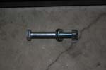
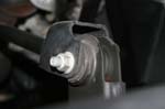
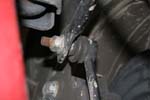
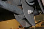
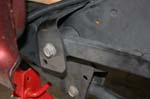
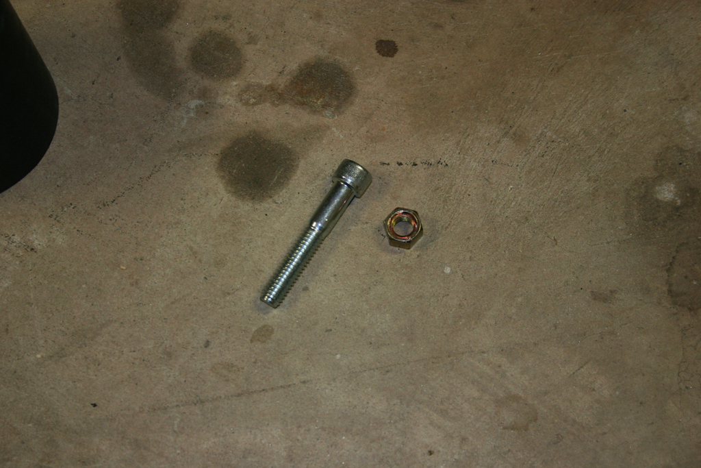
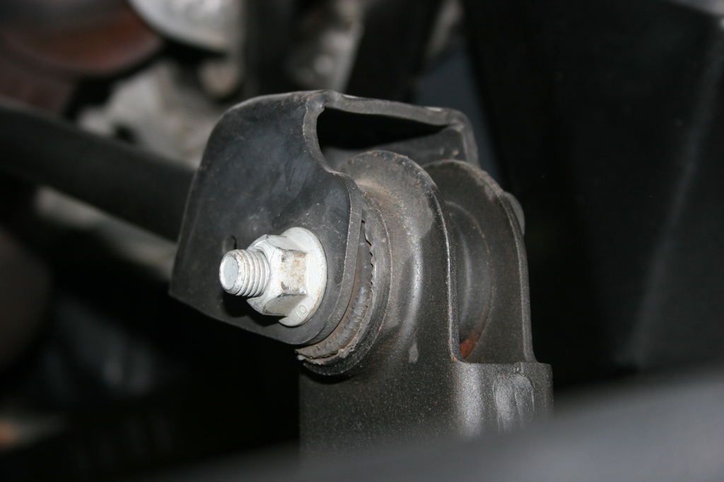
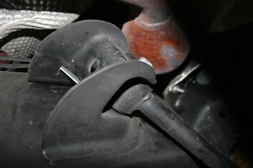
| 18. Upper control arms. A new metric bolt is provided for the passenger side frame mount. You will be cutting this bolt off to remove the arm. It hits the exhaust manifold and can not be removed without moving the engine. Simpler to cut and replace it. |
 |
 |
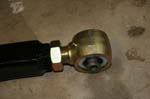
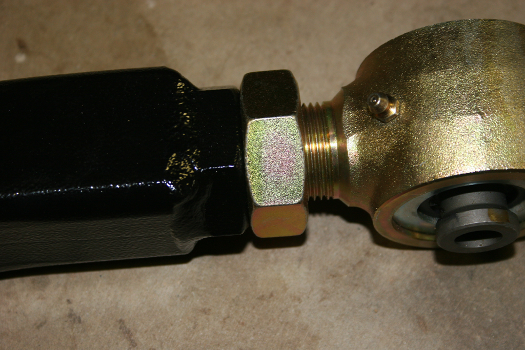
| 19. Find the upper control arms and install the zerk fittings. Do not overtighten the zerk fittings, you will snap them off. You will need a 5/16" combo wrench or socket. |
 |
| 20. Adjust the Upper control arms to 18.75" in length. Snug up the jam nut, we will tighten it once the arm is installed. |
 |
 |
| 21. Support the pinion with a floor jack. You can use your scissors jack for you Jeep here. See there is a use for that thing other than rusting in the back cubby hole. |
|
|
| 22. Remove the upper control arms. You will need to cut the passenger side frame side bolt to remove it. Be careful with the driverside bolt at the axle. On the Rubicon models the electrical connectors for the lockers are near the bolt, and the cables connect to the control arm. You will need to disconnect the cable from the control arm. You will need a |
 |
 |
 |
 |
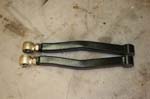
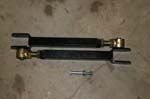
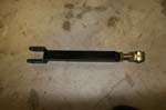
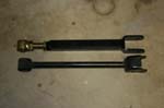
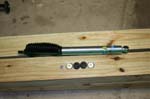
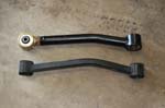
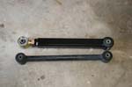
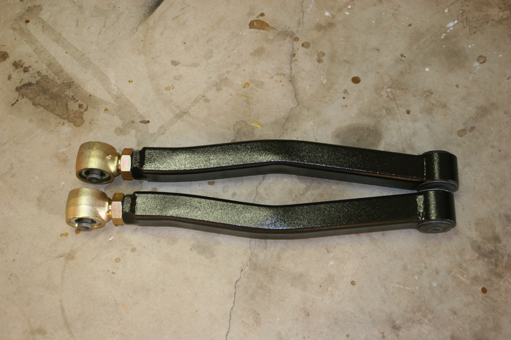
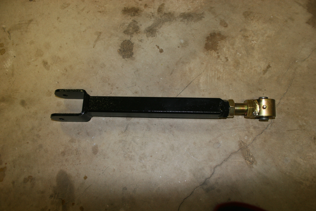
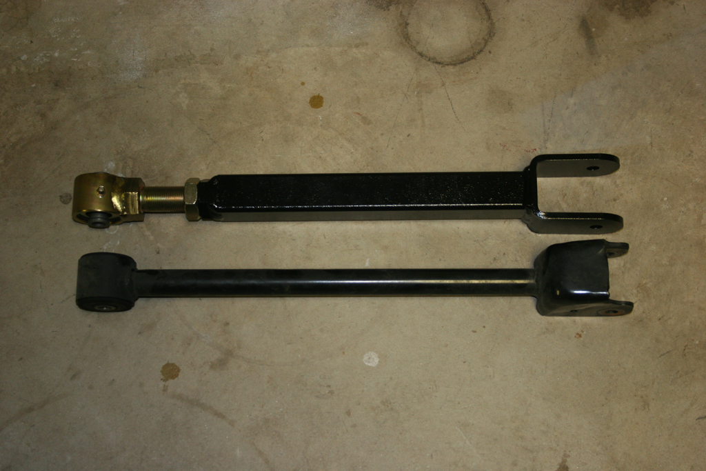
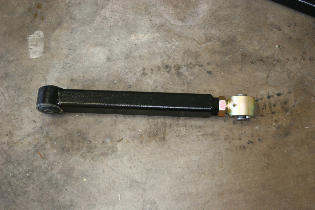
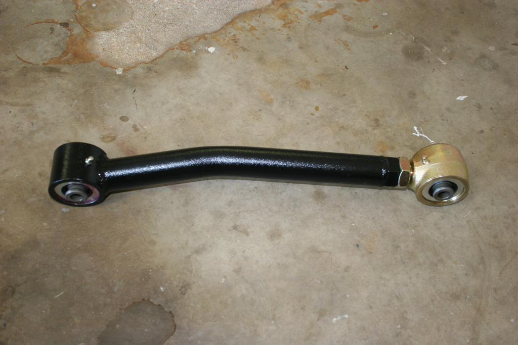
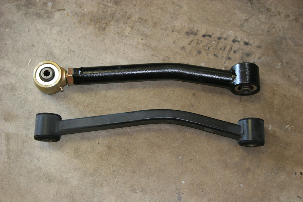
| 22a. Quick comparison shot of the Clayton arm compared to the stock arm. The stock arm is fairly beefy compared to the older TJ arms, but still pales in comparison to Claytons arm. |
 |
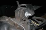
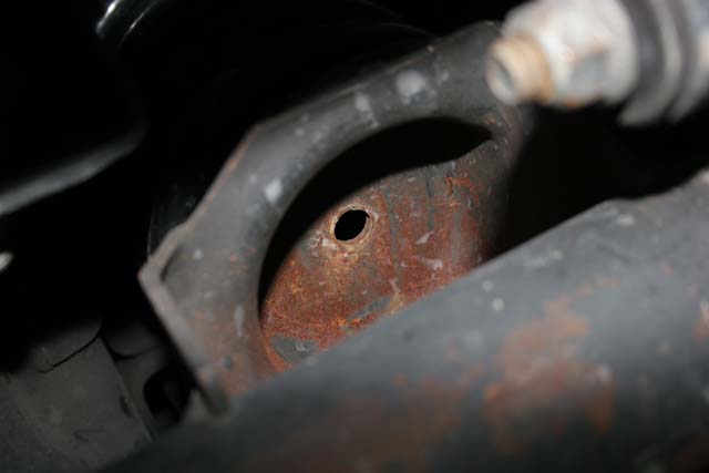
| 23. The BLACK HOLE! The fun part of installing the new upper control arms is the passenger side frame mount. You will need to slide the new provided bolt through the frame, into the arm and then out the other side of the mount before you can put a nut on it. This is made more difficult by the tiny hole you have to slide it through. I dropped it twice before I got it lined up and through. Fishing the bolt out of the frame is a fun adventure. Of course the bolt is the easy part to get out, the washer also goes down with it... |
 |
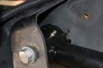
| 24. Bolt in the new upper control arms. You can use the jack under the pinion to rotate the axle to line up the axle side bolt holes. Be careful with the driverside bolt at the axle. On the Rubicon models the electrical connectors for the lockers are near the bolt. You can install these arms with the grease fitting facing down. |
|
|
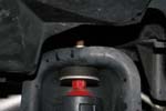
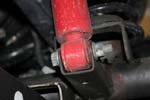
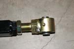
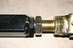
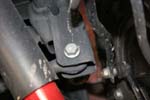
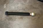
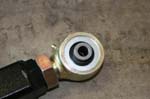
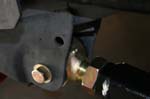
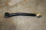
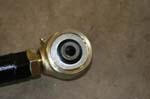
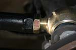
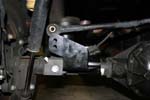
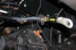
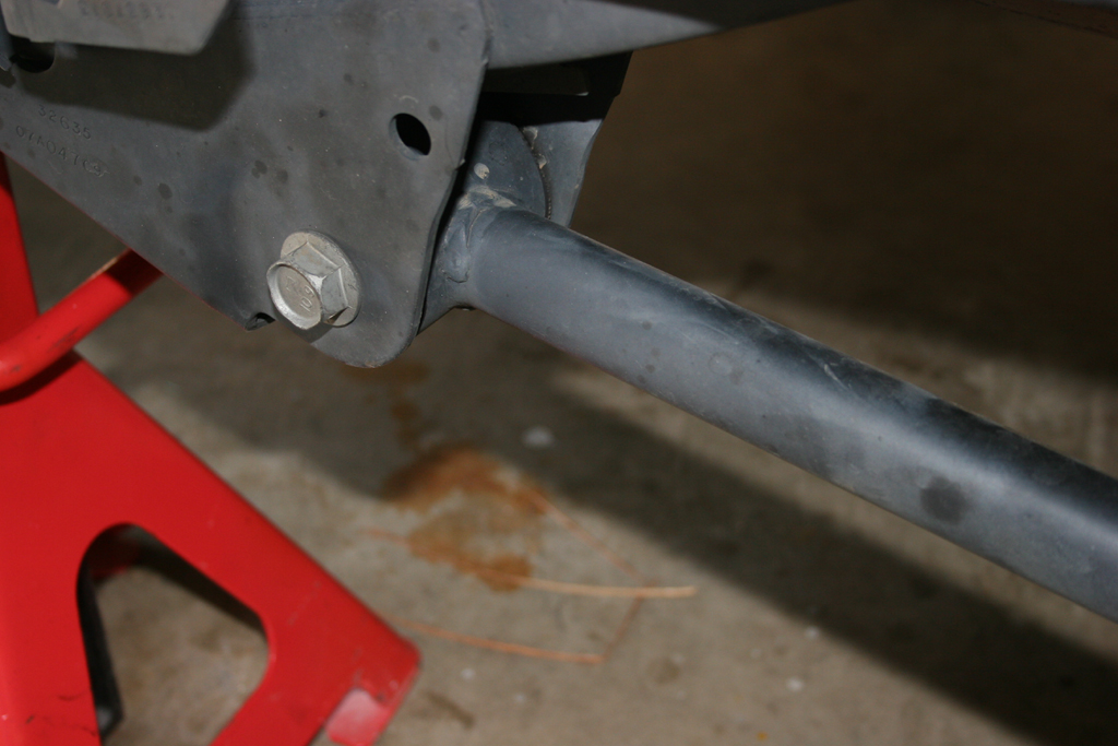
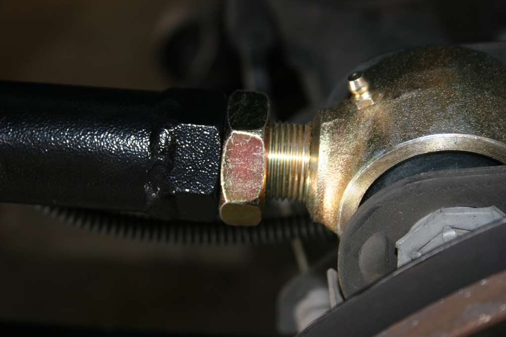
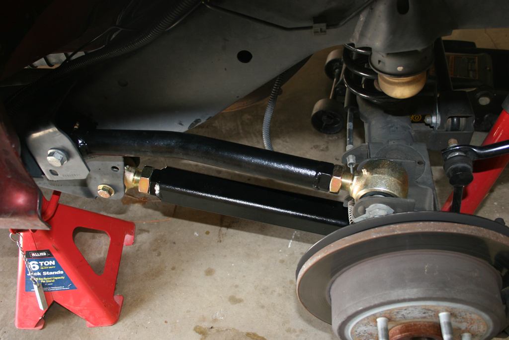
| 25. Install the front adjustable Trackbar. Adjust the trackbar to 32 7/8" center to center. The Bushing goes on the axle side, and the heim joint goes on the frame size. The installation is similar to the JKS front adjustable trackbar. Do not tighten up the bolts. |
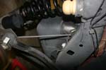
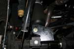
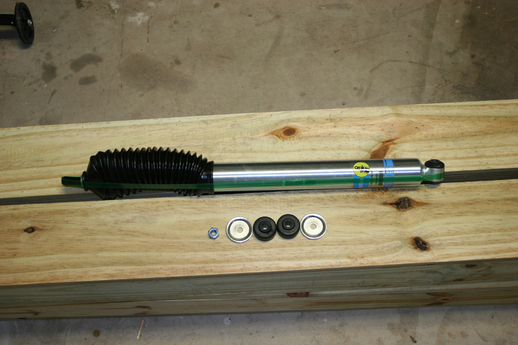
| 26. Install the new front shocks. The lower bolt needs to be installed from the inside to allow for clearance of the lower control arm. The nut should be closest to the tire. |
 |
|
| 27. Jack up the front suspension and install the tires. We will do the brakelines and anti-sway bar link later. |
| |
| Rear Suspension Installation: |
| 1. Jack up the rear suspension and support the Jeep with Jack Stands in front of the lower control arm. Remove the tires. Leave the floor jack under the axle to relieve some pressure on the bolts for the next couple of steps. |
| 2. Loosen the following bolts: Upper control arms and lower control arms. You will need a 18mm and 21mm socket and combo wrench. |
 |
 |
 |
 |
| 3. Remove the following bolts/nuts: |
Lower shock bolts, upper shock bolts. You will need a 18mm socket and combo wrench for the lower and a 16mm socket and long extension for the top.
|
 |
 |
Rear anti-sway bar lower bolt, rear anti-sway bar upper nut. You will need a 18mm socket and combo wrench and a 19mm combo wrench. This Anti-sway bar link will be reused in the front if you do not have the optional JKS quick disconnects.
|
 |
 |
Rear trackbar lower bolt, rear trackbar lower bolt. You will need a 21mm socket and combo wrench.
|
 |
 |
Brake line mount to frame. You will need a 10mm socket.
|
 |
 |
Emergency Brake bracket. You will need a 10mm deep well socket. I left the cables free of the bracket, though I did bolt the axle back into place to avoid loosing it. |
 |
| 4. Unclip the speed sensor cables from the frame for each wheel hub. You will need the extra slack. |
 |
 |
| 4a. For Rubicon models, you may need to unclip the rear locker cable to the differential. |
 |
 |
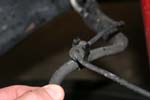
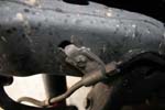
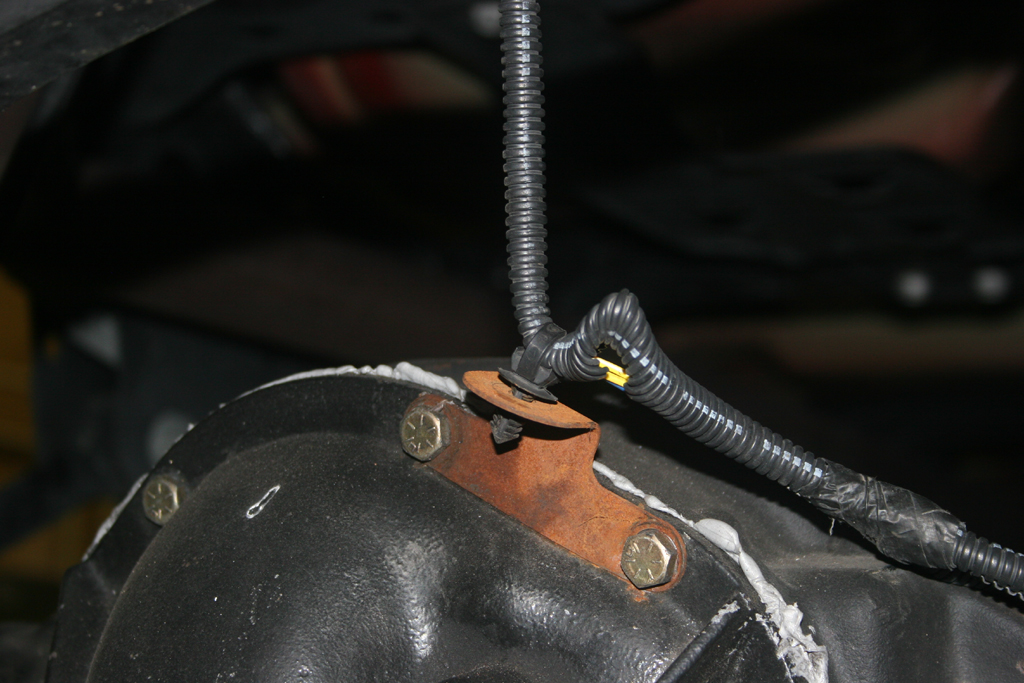
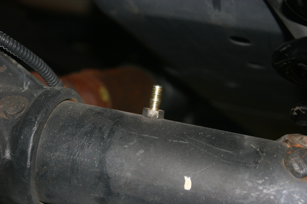
| 5. Slowly twist and work the rear differential breather line off of the fitting on the axle. |
 |
 |
| 6. Slowly lower the axle down towards the ground. Watch the brake lines, speed sensor lines and the locker cable on the differential. |
|
|
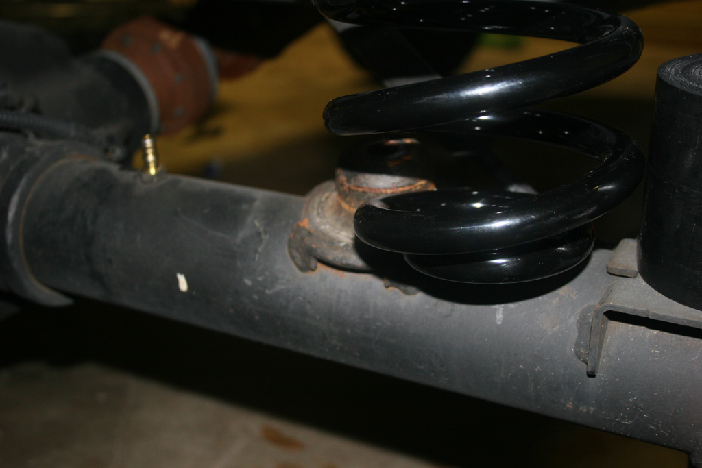
| 7. Remove your rear springs. They should just pull right out. |
|
|
| 7a. Quick comparison shot |
 |
| 8. Lift the Clayton spring up around the upper bump stop (small hole down) and push the spring over the lower spring mount. A large flat screwdriver can help wedge the spring up and over. A few other ways are jacking up the opposite end of the axle, using a spring compressor, or a large friend standing on one end of the axle. |
 |
 |
9. Repeat the steps for the opposite side. You will need to jack up the side you just did to assist in getting the springs in on this side.
Note: Be careful you do not lift the Jeep off of the Jack stands and release the pressure to fast afterwards. |
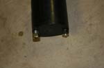
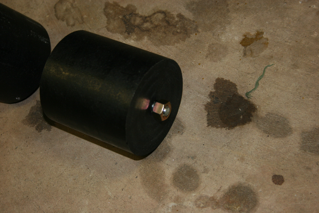
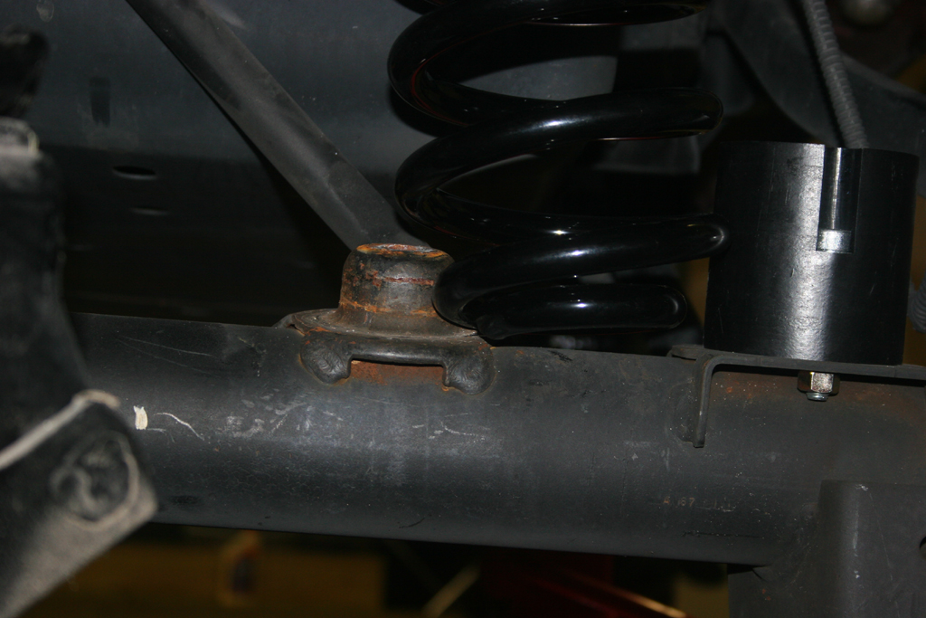
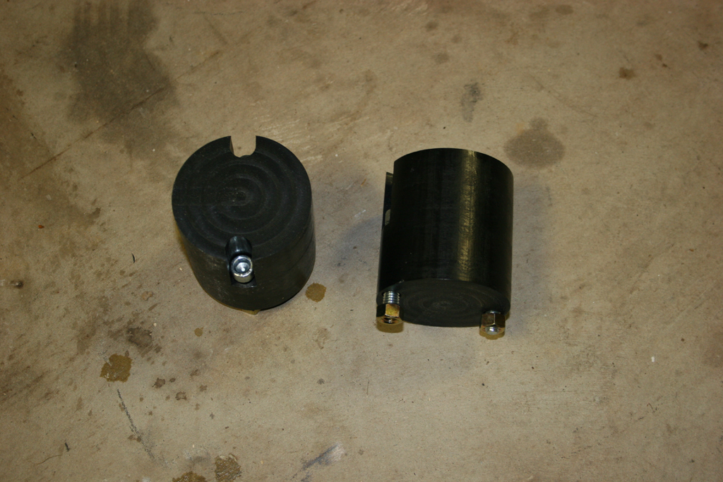
| 10. This is what the bump stops with the screws look like. The nut gets screwed onto the bolts from below the pad on the axle. |
 |
 |
| 11. Install the bumpstop on the pad and tighten up the two bolts. You will need a 5/16 " allen wrench and a 9/16 " combo wrench. |
 |
 |
| 12. Find the lower control arms and install the zerk fittings.Do not overtighten the zerk fittings, you will snap them off. You will need a 5/16" combo wrench or socket. |
 |
 |
| 13. Adjust the lower control arms to 20" in length. Snug up the jam nut, we will tighten it once the arm is installed. |
|
| 14. With the suspension lowered. Remove the lower control arms. You will need a 21mm socket and combo wrench. |
 |
 |
 |
| 15. Install the Lower control arms. The lower control arm bushing goes on the axle side. You will need a 21mm socket and combo wrench. |
 |
 |
| 16. Find the upper control arms and install the zerk fittings.Do not overtighten the zerk fittings, you will snap them off. You will need a 5/16" combo wrench or socket. |
 |
 |
| 17. Adjust the Upper control arms to 3/8 inch longer than stock length. Snug up the jam nut, we will tighten it once the arm is installed. |
|
|
| 18. Support the pinion with a floor jack. You can use your scissors jack for you Jeep here. See there is a use for that thing other than rusting in the back cubby hole. |
|
|
| 19. Remove the upper control arms. You will need a 18mm socket and combo wrench. |
 |
 |
| 19a. Quick comparison shot of the Clayton arm compared to the stock arm. The stock arm is fairly beefy compared to the older TJ arms, but still pales in comparison to Claytons arm. |
 |
 |
| 20. Bolt in the new upper control arms, the bushing goes on the frame side. You can use the jack under the pinion to rotate the axle to line up the axle side bolt holes. Be careful with the driverside bolt at the axle. On the Rubicon models the electrical connectors for the lockers are near the bolt. You will need a 18mm socket and combo wrench. |
 |
 |
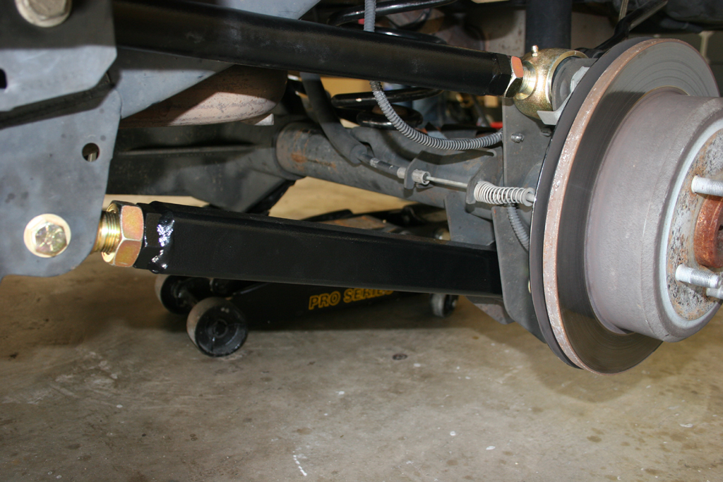
| 20a. Both arms installed. |
 |
| |
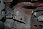
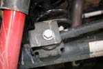
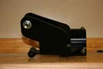
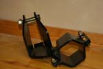
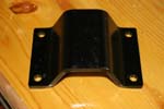
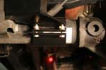
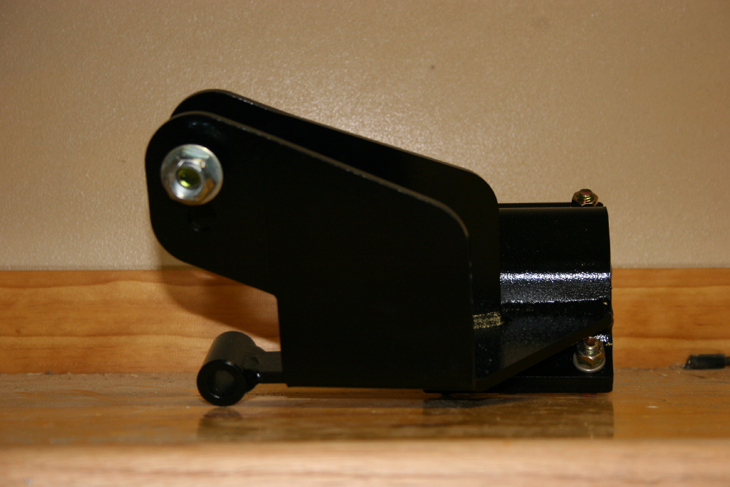
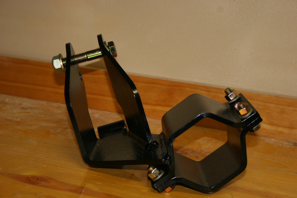
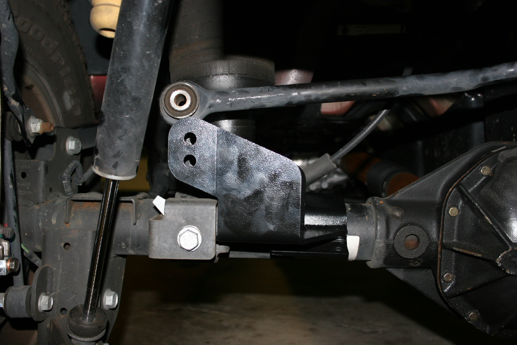
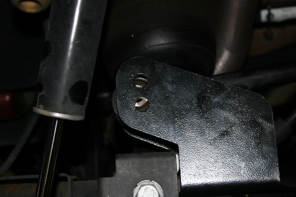
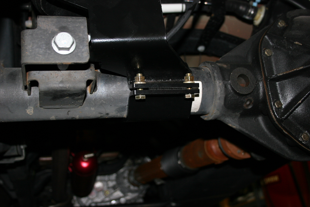
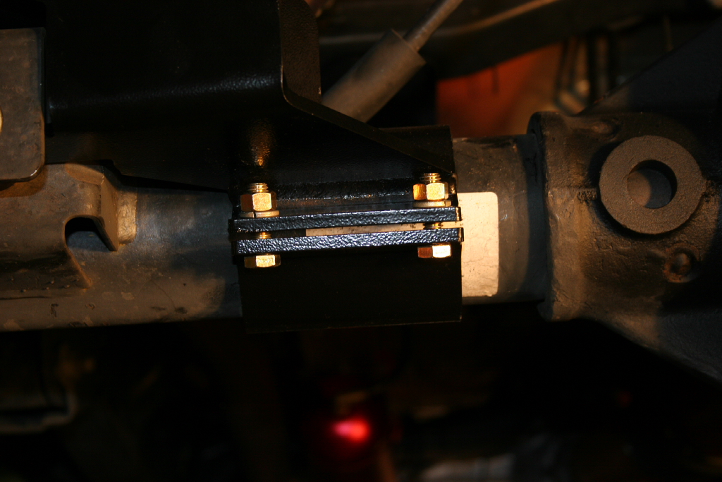
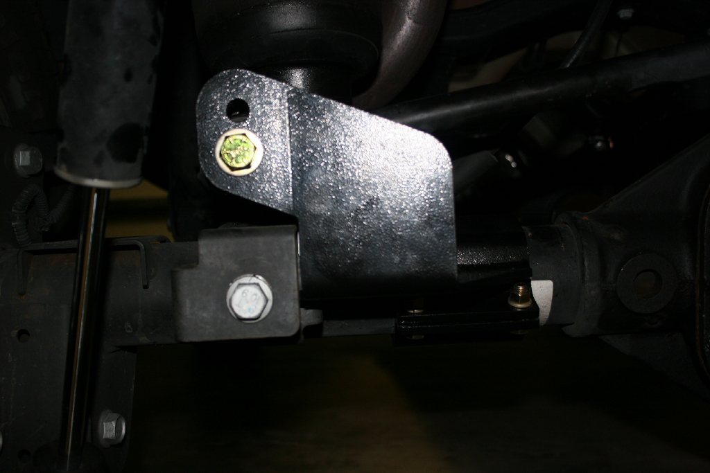
| Rear Trackbar Bracket Installation: |
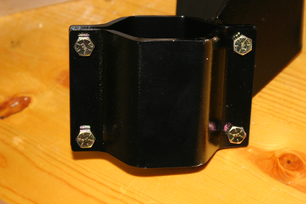
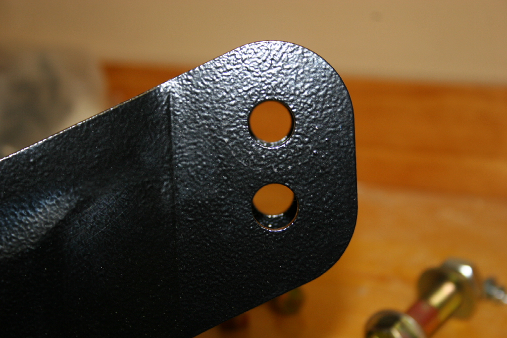
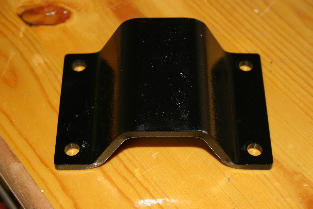
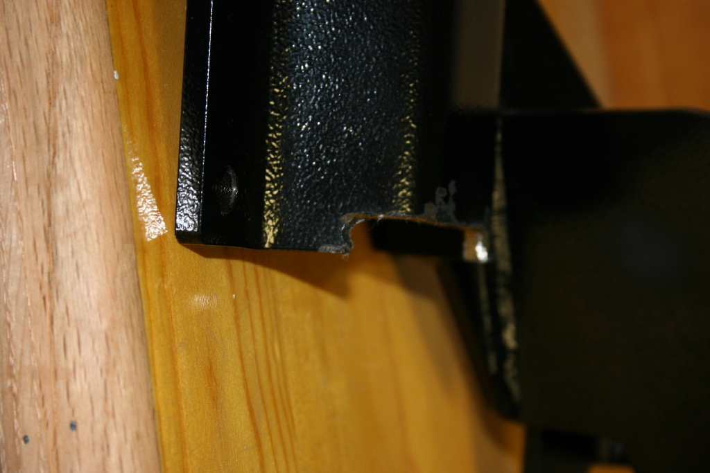
| A few pictures of the bracket. Very heavy duty bracket. |
 |
 |
 |
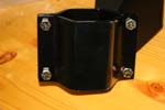 |
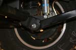
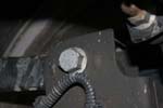
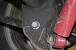
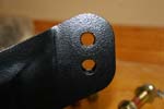
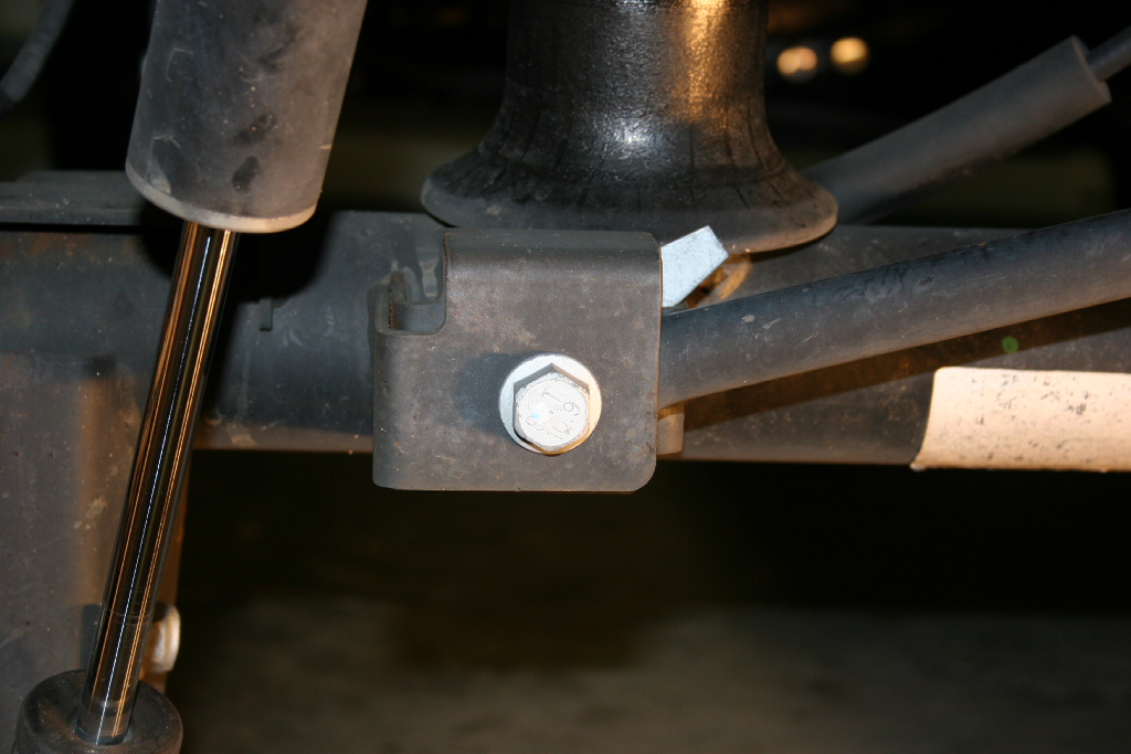
| There are two mounting holes for the trackbar. The lower hole is for the 3.5" lift, while the upper is for the 4.5" lift. Like always you will need to double check your axle position once you have the lift completed and everything tightened up. You may still need an adjustable trackbar to get the axle positioned perfectly. Mine was off just a little in the 4.5" lift position. |
 |
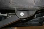
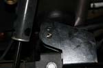
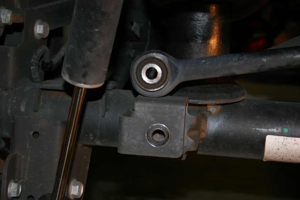
| 1. Remove the lower axle bracket half from the trackbar bracket. |
 |
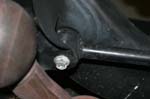
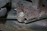
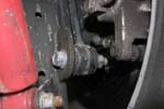
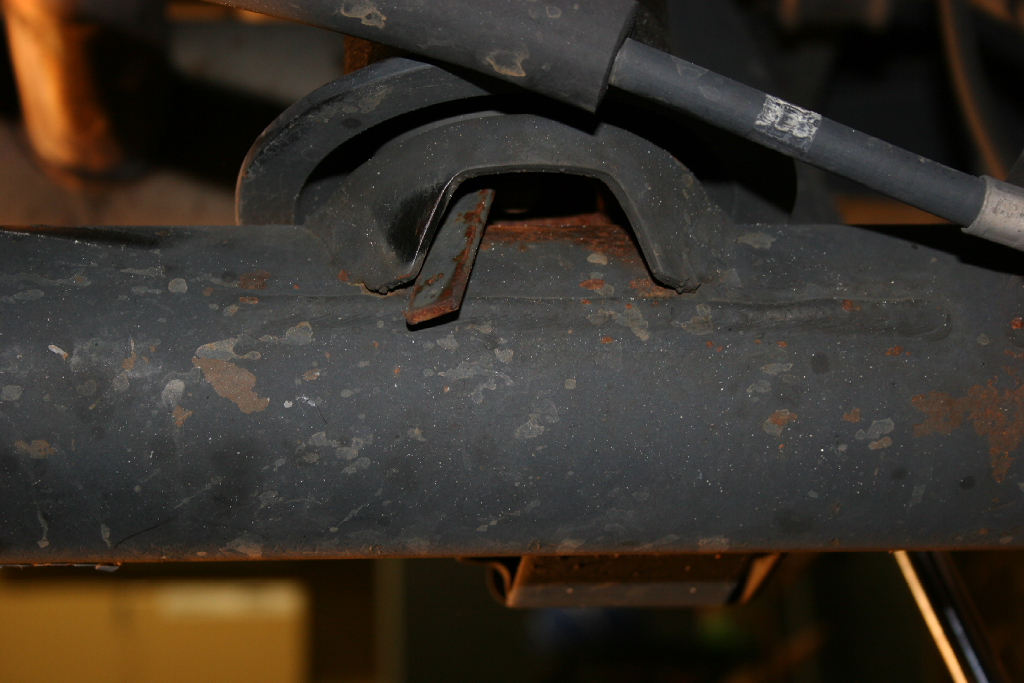
| 2. There may be a 3 to 4 inch weld on the backside of the axle that needs to be ground down to allow the bracket to fit correctly. Install the bracket into the stock mounting location. Reinstall the factory bolt. You will need a 21mm socket. |
 |
 |
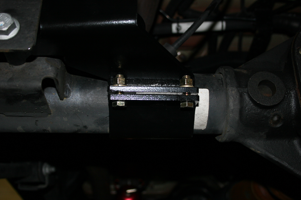
| 3. Install the lower axle bracket half to the trackbar bracket. Ensure you get the bracket evenly tightened. You will need a 9/16" combo wrench and socket. |
 |
| 4. If you have the 3.5" lift, you will use the lower of the two (2) holes for your trackbar. The upper hole is for the 4.5" lift. Use whichever aligns your lift the best. Some 3.5" lifts may align better in the top hole. |
 |
| 5. Reinstall the trackbar using the factory bolt into the frame side bracket. You will need a 21mm socket and combo wrench. |
|
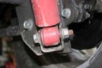
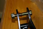
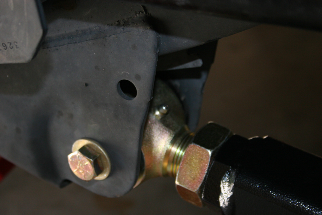
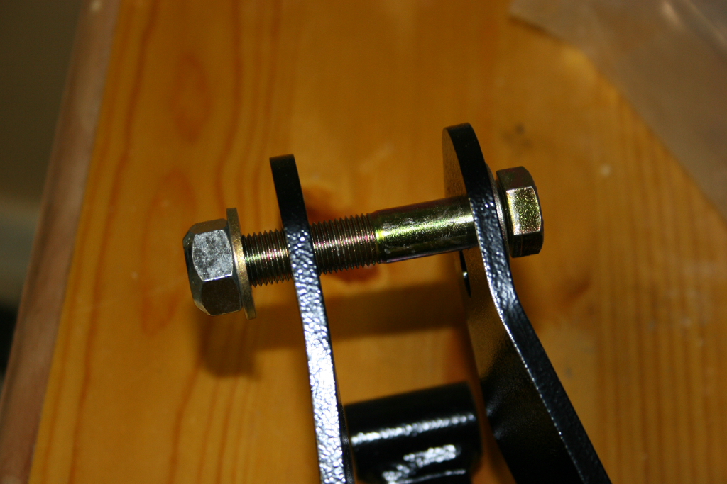
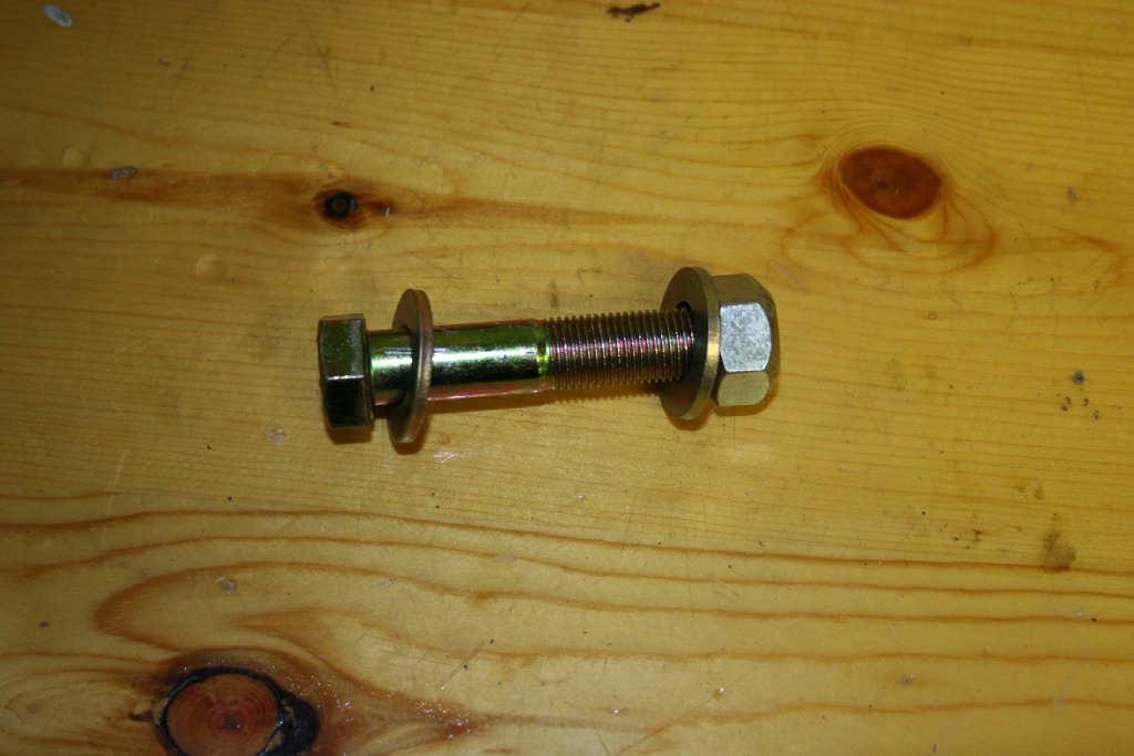
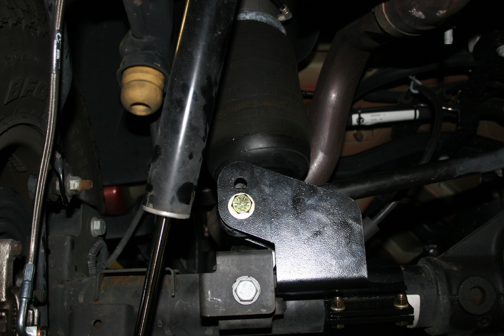
| 6. Using the provided bolt. Bolt the trackbar into the Clayton trackbar bracket. You will need a 7/8" combo wrench or socket and 13/16" socket or combo wrench. |
 |
 |
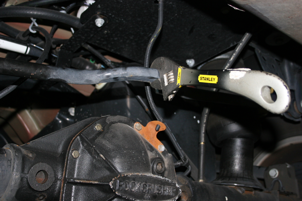
| 6a. You may need to lift the axle, to get things in position. I did need to give the trackbar a little twist to get the screw to line up correctly. I just put a 12' adjustable wrench on the trackbar flat section and gave it a little pull and slid the bolt into place. |
 |
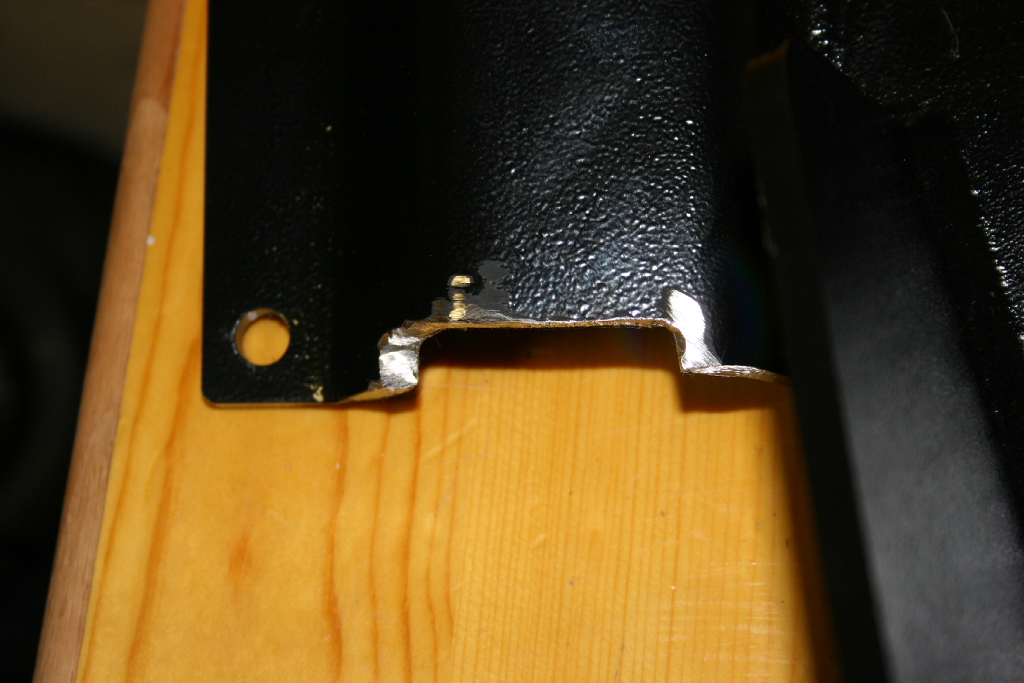
| If your curious as to the Clayton trackbar brace working with an AiROCK suspension, all you need to do is cut a 1/4" notch out of the upper axle bracket near the spring. |
 |
| |
| Rear Suspension Installation continued: |
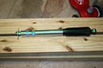
| 25. Install the new rear shocks. You will need a 18mm socket and combo wrench for the bottom and a 16mm socket and long extension for the top. |
 |
|
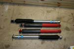
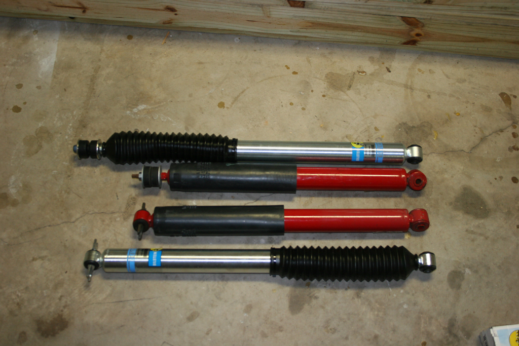
| 25a. Quick comparison shot between the new and old rubicon shocks. |
 |
| 26. Install the provided rear anti-sway bar links. 12.5" for the 3.5" lift, 13.5" for the 4.5" lift. |
|
| 27. Now take the rear anti-swaybar links that you removed and install them on the front using a 18mm socket and combo wrench and a 19mm combo wrench. |
|
| 28. Jack up the front suspension and install the tires. We will do the brakelines later. |
| |
| Finishing up: |
| 1. Install the front and rear extended brake lines. The clayton lines are similar to the Rubicon Express extended brake lines. You will need a 12mm to undo the hardline, a 15mm to remove the banjo bolt from the caliper, and 10mm socket to bolt the bracket in place to the frame. |
|
|
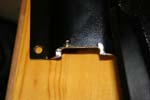
| 2. You may need to trim the rear pinch weld and the rear of the rocker guard. |
|
|
| 3. Adjust your front track using the adjustable track bar. Adjust the rear track as close as you can utilizing the two locations on the trackbar bracket. |
|
|
| 4. Put a jack under the front pinion and remove both upper arms. Adjust the front caster to 4.5 to 5 degrees using the jack. Adjust the arms and reinstall. They do not need to be exactly the same length. |
|
|
| 5. Put a jack under the rear pinion and remove both upper arms. Adjust the rear pinion angle. Adjust the arms and reinstall. They do not need to be exactly the same length. |
|
|
| 6. Adjust your steering wheel to have it centered and straight. |
|
|
| 7. Go through and tighten every bolt and nut your removed and reinstalled, tighten the control arm and adjustable trackbar jam nuts. |
|
|
| 8. Bleed your brakes. |
|
|
| 9. Check your clearance on the rear pinch seam. |
|
|


