I am pretty picky about my wiring systems and professional appearance of lines in the Jeep. I hate seeing some of the sloppy wiring setups that have evolved in jeeps over multiple wiring projects, mine included. I already knew that I would be adding lights, and electronic to my JK and decided that I didn't want to play around and have a spiders web worth of wiring all over the engine compartment, I was already doing AiROCK, so I would have enough wires and line in there. I was looking for a way to set up a professional set of switches and relays for my JK. I had seen sPOD a few years ago and was going to install it on my TJ or LJ, but didn't quite get to that point with them. I talked to the owner John about a sPOD for the JK, I knew this was what I was going to put into the JK. At the time it didn't exist, so after lots of pictures, measurements and conversations it arrived in the mail (twice). Prototyping stuff is absolutely fun, okay maybe I'm a little nuts. My UPS driver even drooled over it when it showed up. It is nice knowing that my Jeep parts are safe.
The system is quality through and through. From the abrasion guard on all the wires to the precise bending of the sheet metal to make the pod, even the electroplated cover on the source. You can't get more compact then what John has put together and stay anywhere in the price range. One of the nice things is that you can use the switch pod and the source separately if you wish. Some people would rather wire up other switch's, but want to use the source for the power source. Even the customer service from John is outstanding, he is great to talk to on the phone.
Overview: |
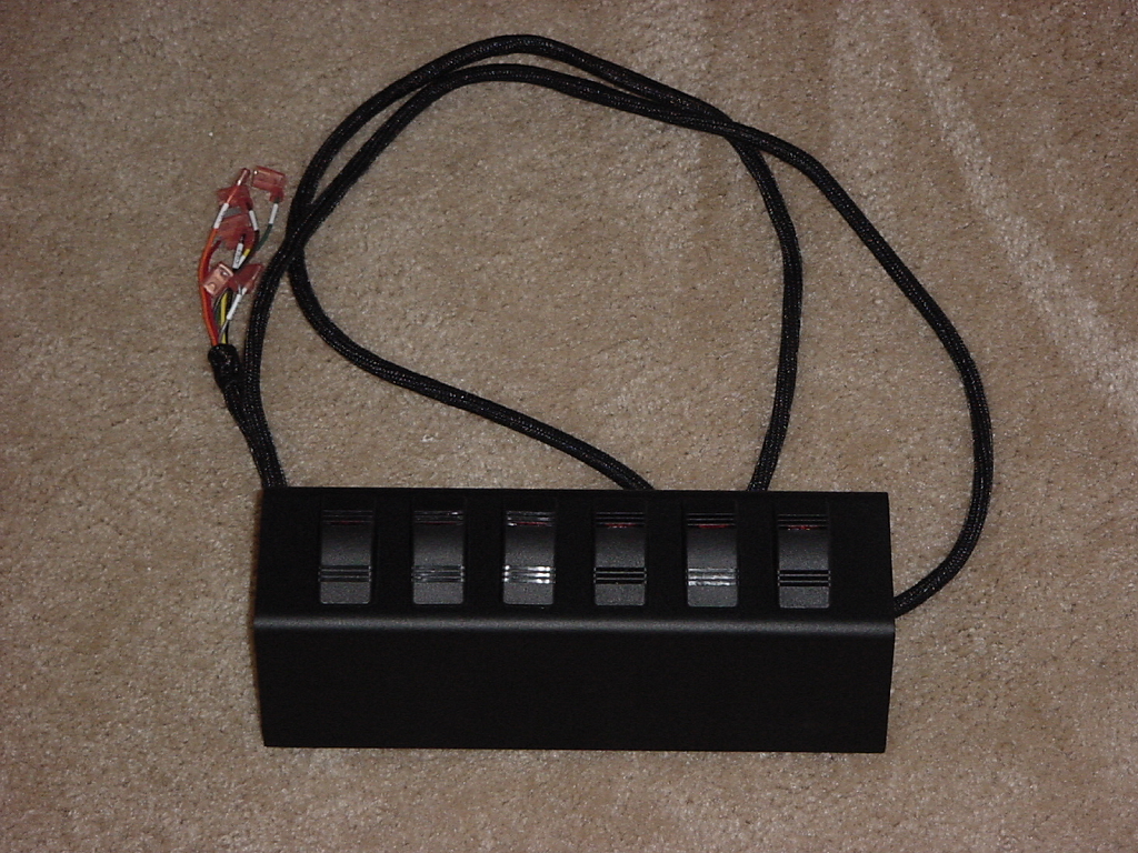
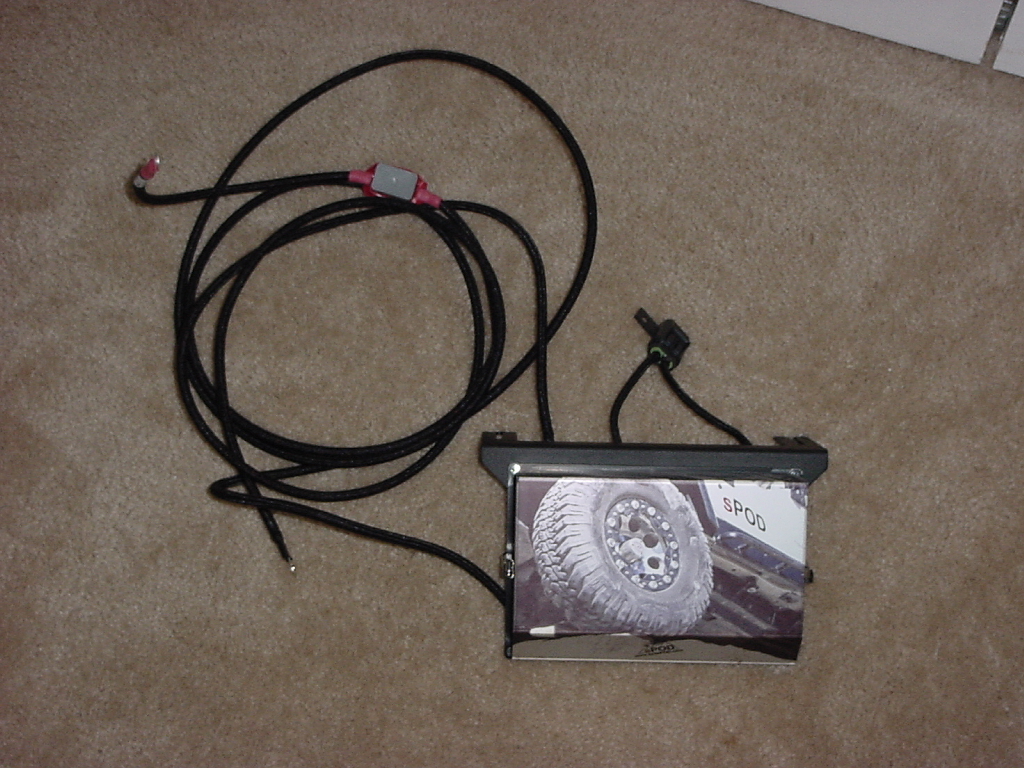
sPOD is basically two parts, a switch panel and the source (relay pack, fuses, connectors) |
 |
 |
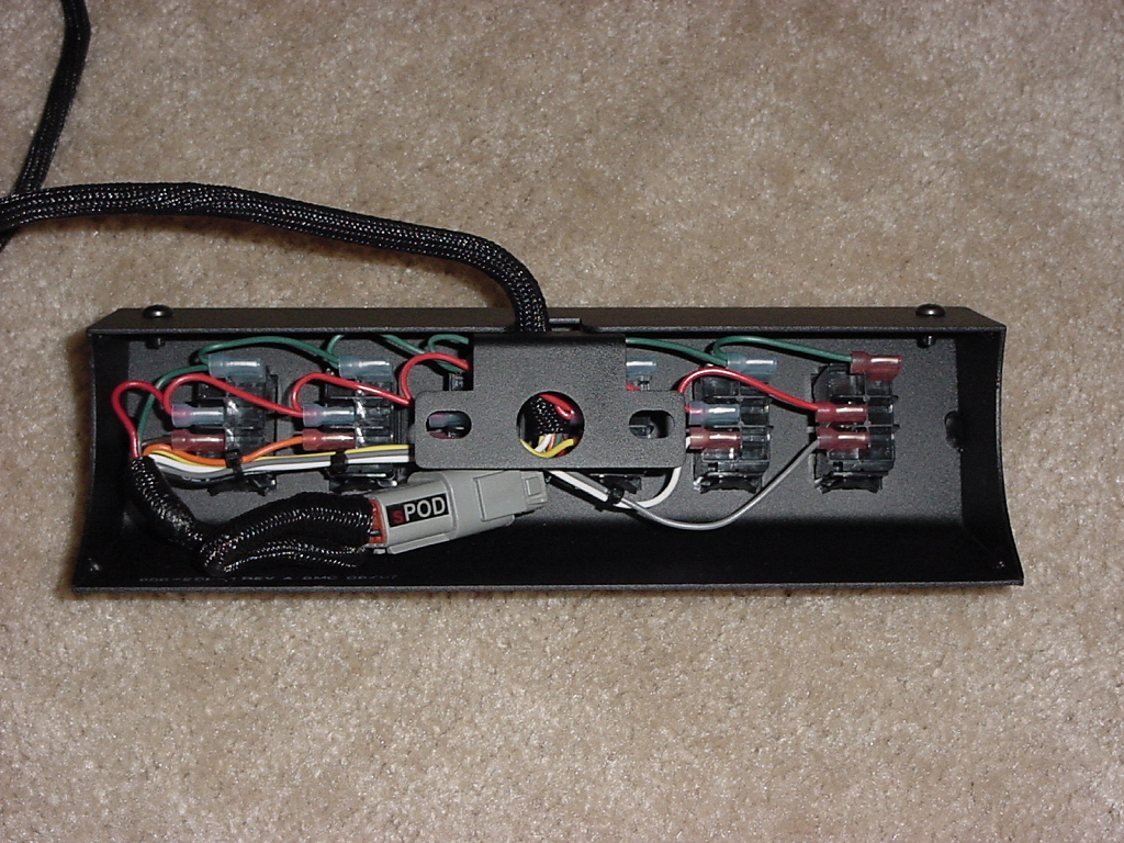
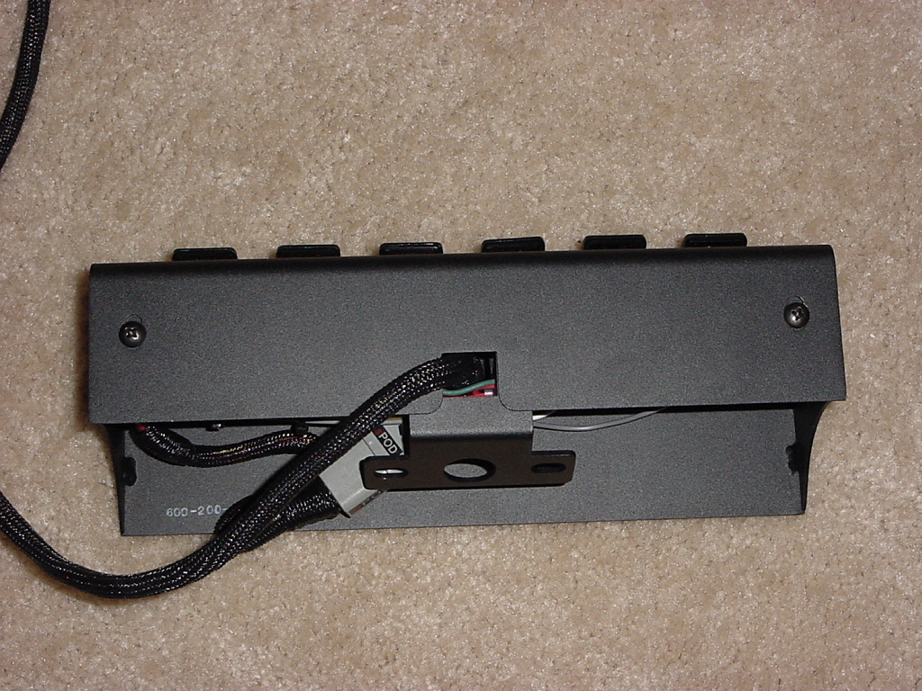
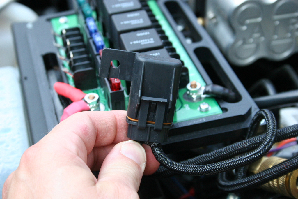
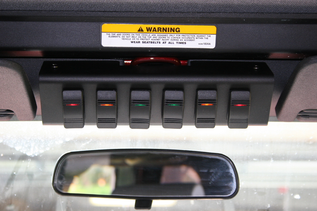
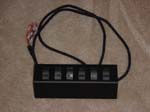
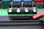
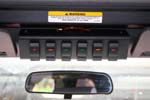
The panel mounts the Contura III rocker switch's. These are some of the best out there, no short cuts taken here. The wiring harness behind is beautiful, all neatly wired and tucked into place. There is a pigtail attached to connect to the wire harness leading to the sPOD. Eventually there will be an option for an air gauge for the JK's if it works out. There wasn't as of this writing. |
 |
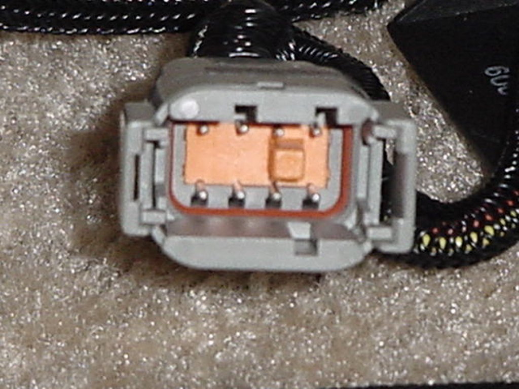
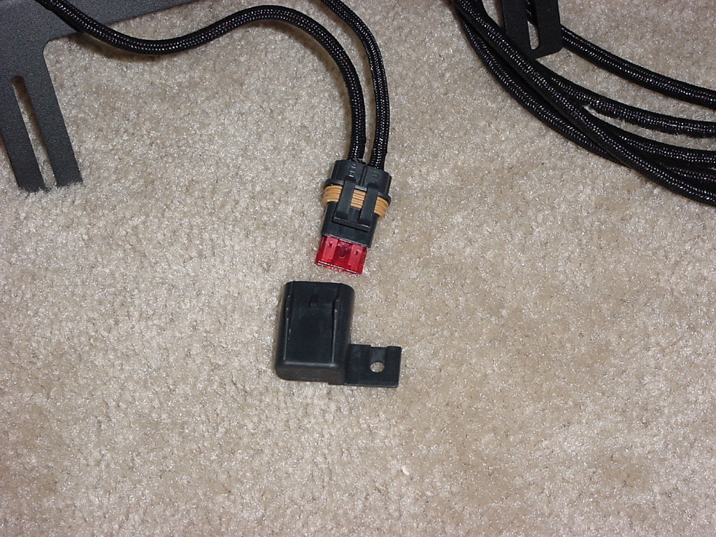
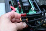
| sPOD comes with a high grade connector on the back. Just to show how much quality goes into this system. It could have easily been done with a cheap connector that you could get at radio shack, or even cheaper some spade connectors. |
|
|
| A look inside the connector. It is even keyed so you can't put it back together the wrong way. This connector is waterproof, but if the water gets to the top of the windshield, I hope I have a scuba tank. |
|
|
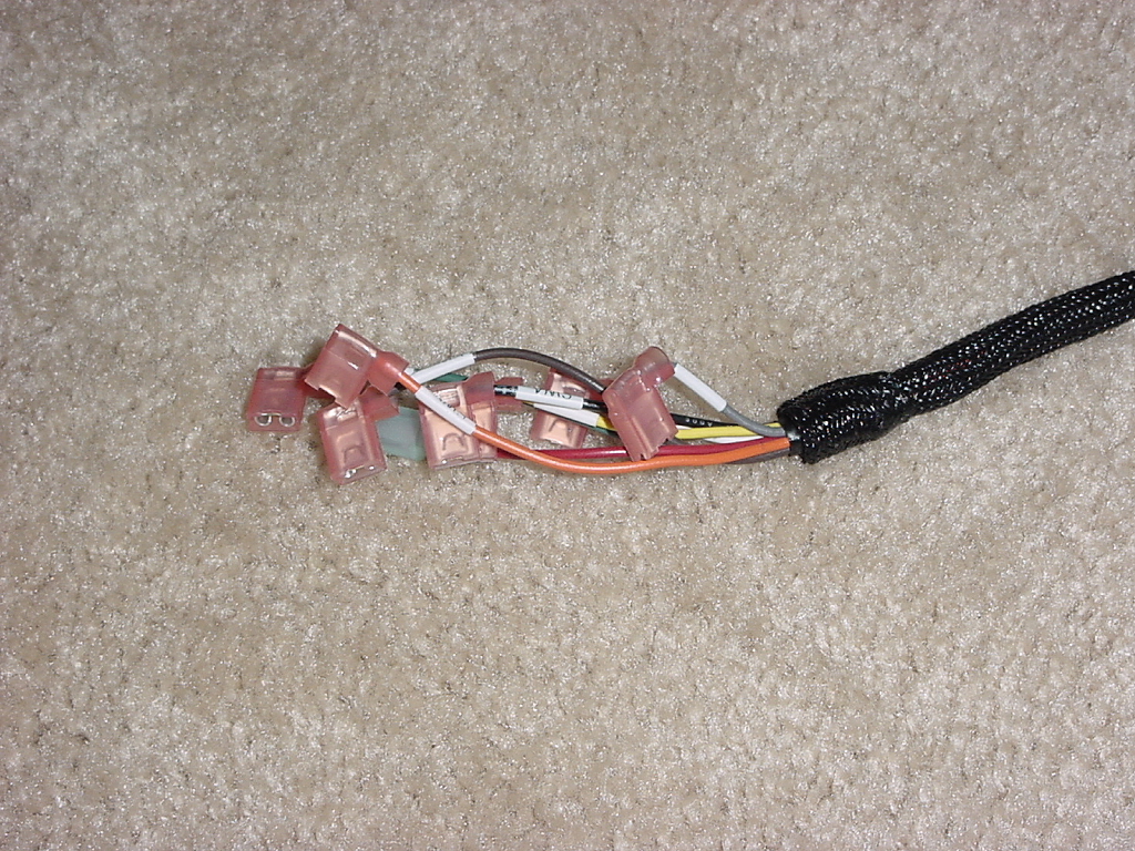
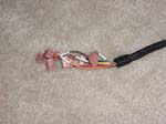
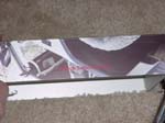
| The switch end is terminated each with a different length to fit perfectly onto the connections points inside the source. The entire wire bundle is wrapped tightly in a loom. |
 |
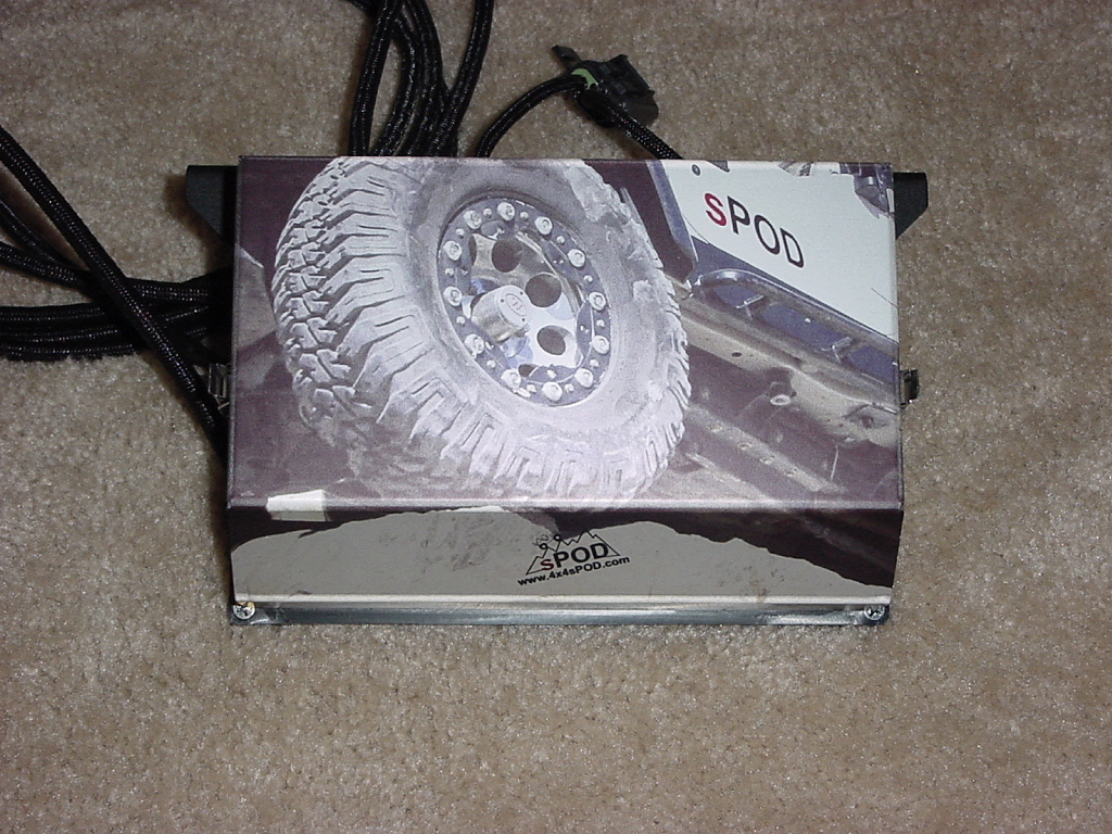
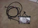
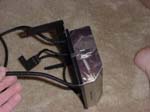
| sPOD has this really sweet anodized cover, just one of those cool touch's. The cover protects the circuit board and relays underneath. |
 |
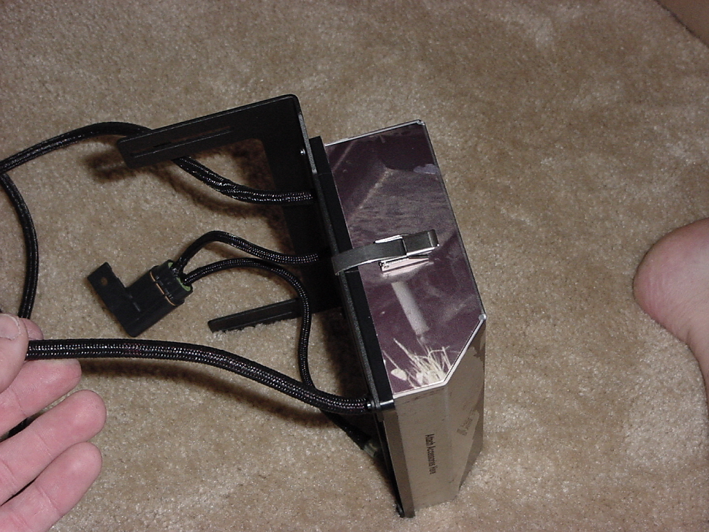
| The cover clamps down to the base with two metal clips on either side. Once more not some cheap part. |
 |
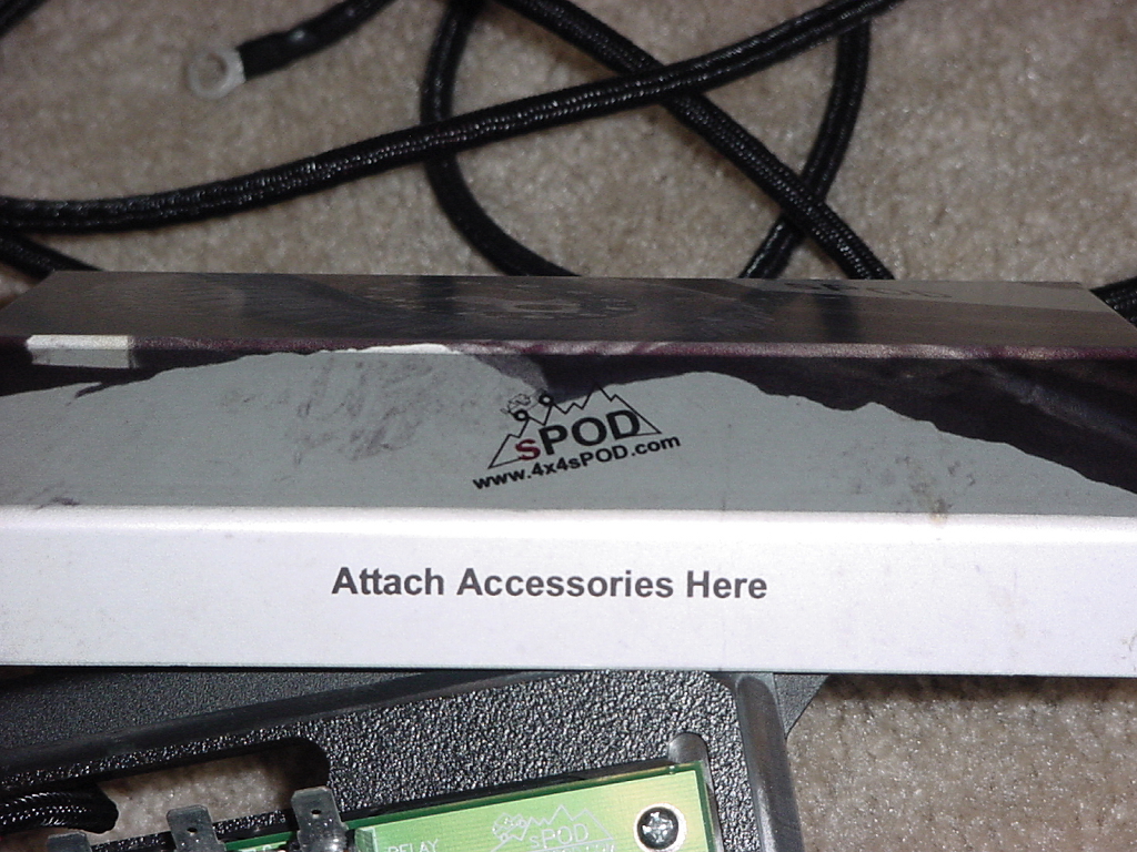
| sPOD even included some wording as to where things go under the cover, "on the cover". Though as guys we probably should have had pictures. |
|
 |
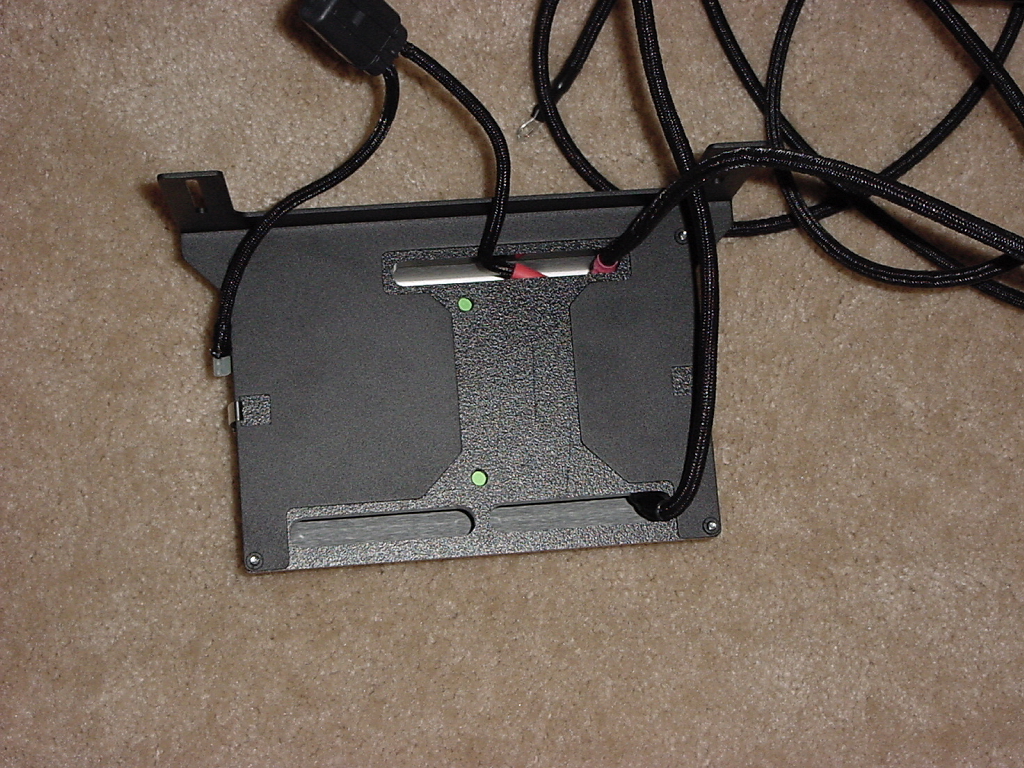
| Even the underside is nice and clean with the battery leads and switch fuse all prewired. |
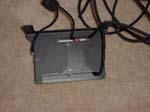 |
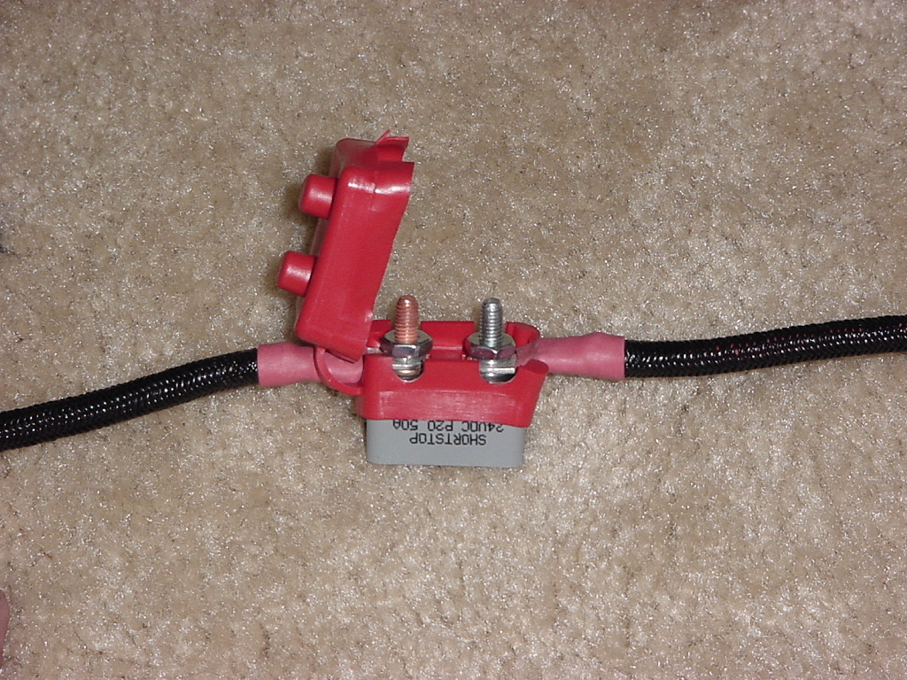
| The source comes with a resetable 50 amp circuit breaker and a fuse to protect the contura switch's. |
|
|
|
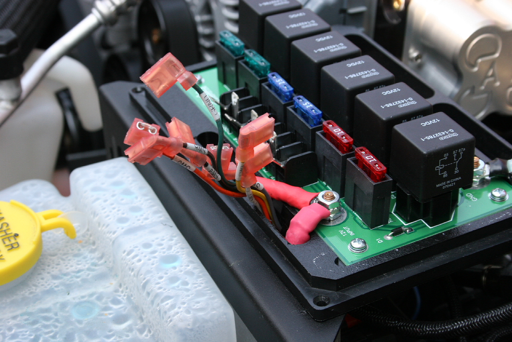
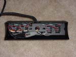
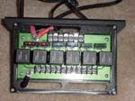
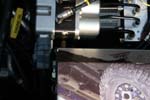
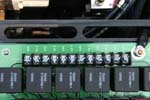
| A quick peak under the hood of the source. Note, how all the relays, fuses, switch connections, and accessory connections are all neatly attached into a compact area, no more fuses, relays, and wires all over the engine compartment. The source houses the 6 replays, fuses, accessory mounting strip and the switch connectors. Everything wires up from underneath through the provided slots in the base. |
 |
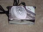
| What I don't have pictured is the instructions. Even with the prototype system, John sent along some beautiful color photos on heavy gloss paper. Not the cheap copied a million times instructions that you can barely read that are so common today. Just one more part that speaks of quality. |
|
| |
| Installation: |
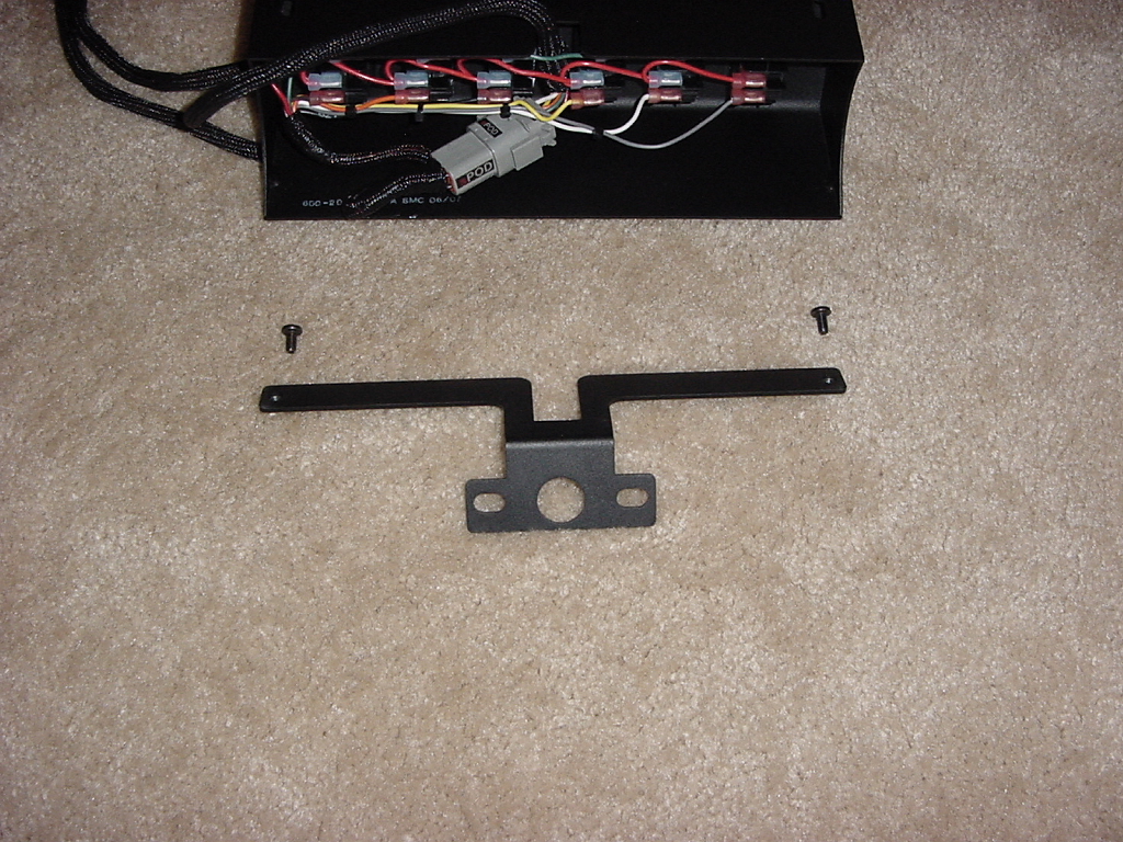
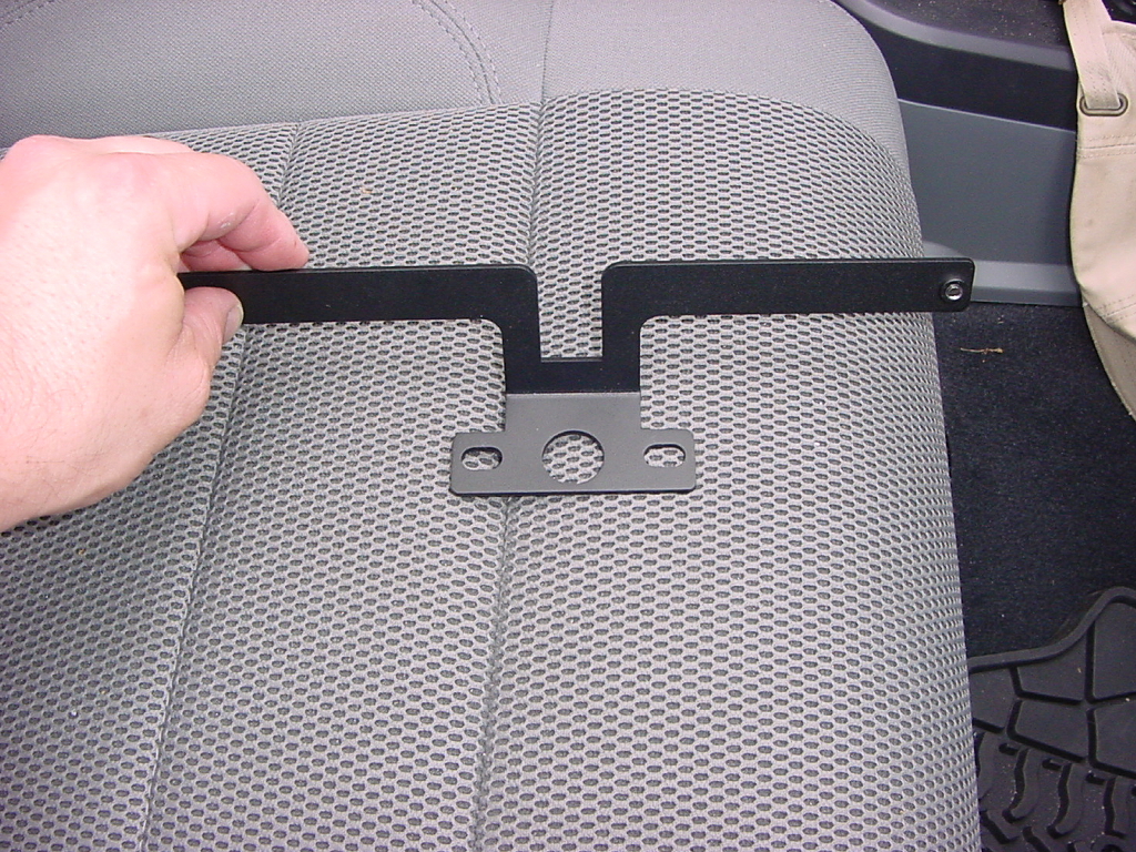
| Remove the mounting bracket from the switch panel. Remove the two phillips screws from the top and slide out the bracket. |
|
 |
| Either fold back your soft top or remove the front panels of your hard top. This makes installation easier. |
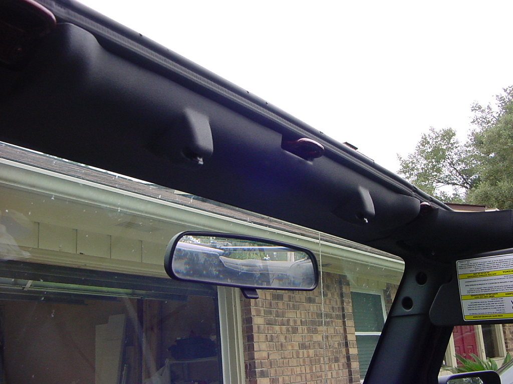
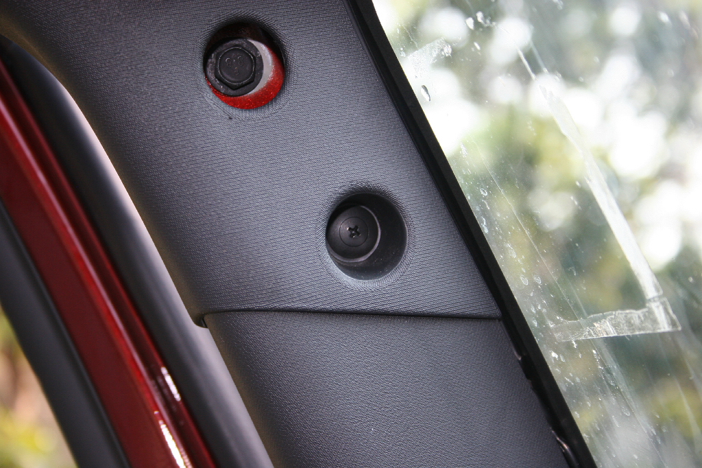
| Fold out your sun visors and remove the center section of your windshield molding. This just pulls off. Check to make certain that you did not leave any of the retaining clips in the windshield frame. They are easily removed with a pair of pliers. |
|
 |
| Place a piece of tape over the defroster duct. I won't comment on how noisy the two washers and the piece of rivet are inside there. Almost as noisy as the pieces of metal up in the windshield that were caused by prototyping ideas. LOL.. |
 |
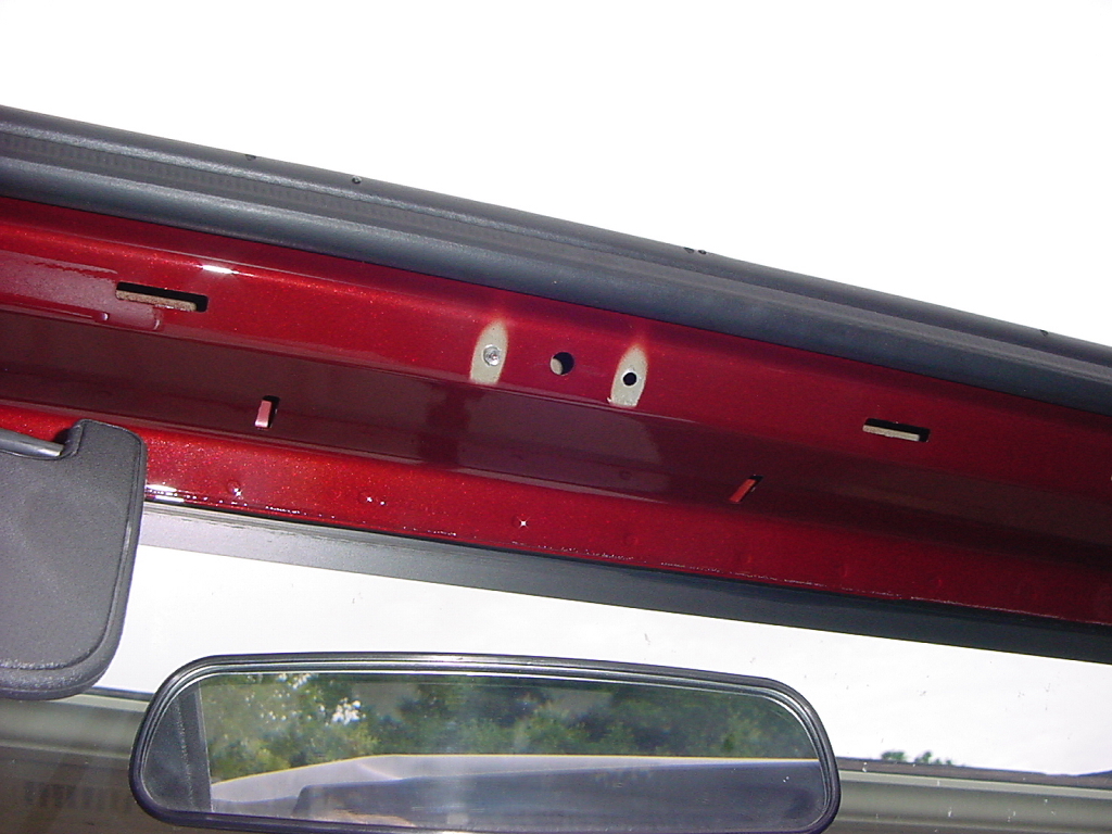
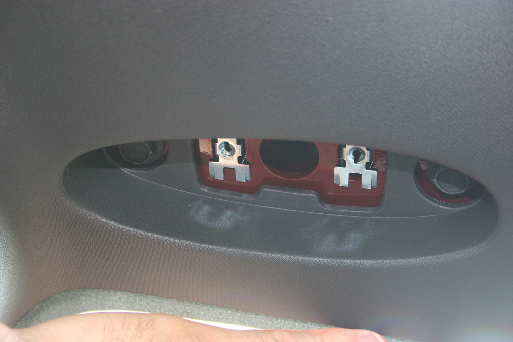
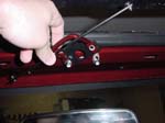
| With a 1/4" Drill bit, drill out the two rivets holding your footman's loop in. Jeep did a good job on mine pulling a rivet into the frame and tearing up the hole. |
|
|
|
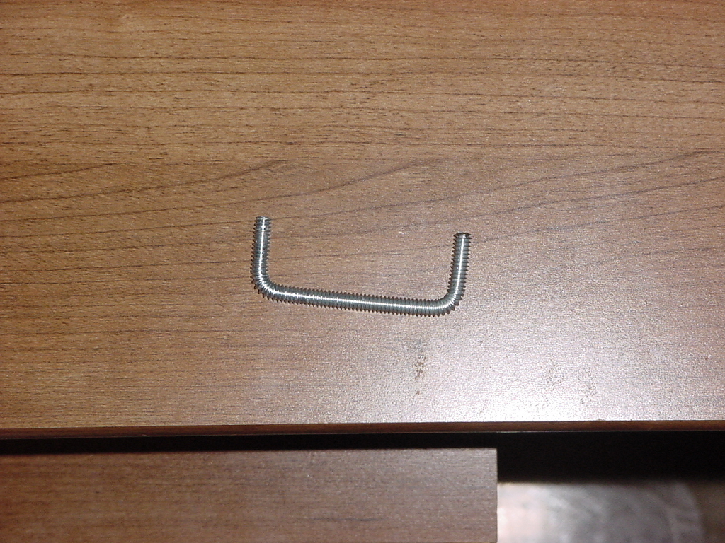
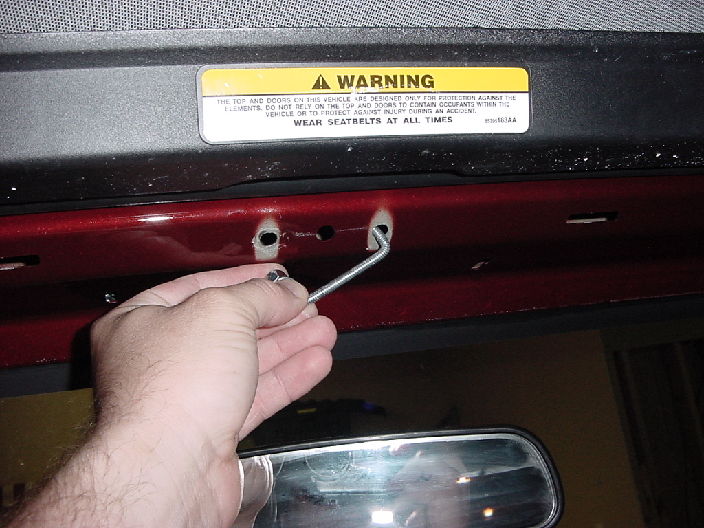
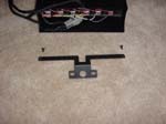
| A few idea's were thought about to mount the switch panel bracket to the windshield. Screws, nutsert (jack nuts), and currently just a piece of formed all thread. This is pictures of the prototype, before we realized that it needed a bend in the center to clear the alignment pin on the windshield molding. |
|
|
The all-thread should have a nut on one side, this will prevent it from falling inside the windshield frame. Thread the all-thread into the rivet hole on one side and then out the other side. |
|
|
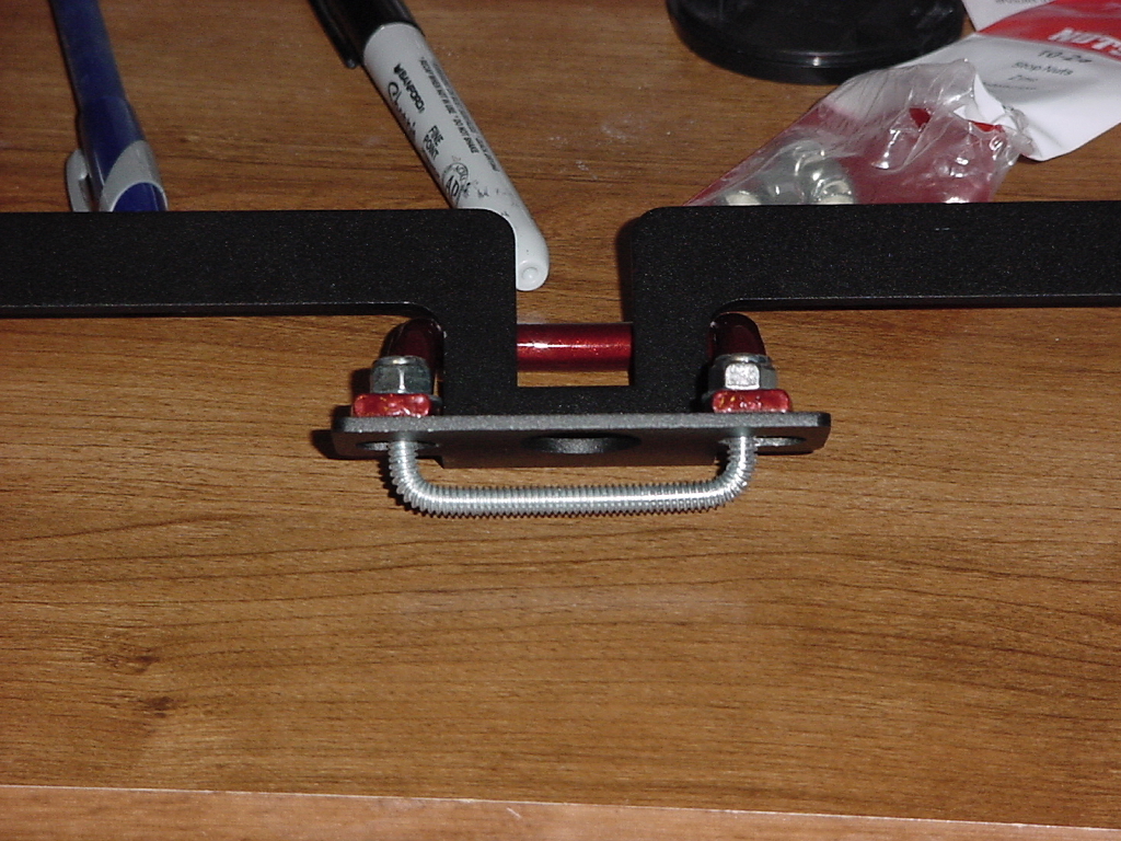
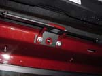
| Place the footman's loop over the switch bracket as shown. The bracket should be sandwiched between the footman's loop and the windshield when completed. |
|
|
| This is a little tricky, but place the switch bracket and footman's loop over the exposed end of the all-thread, install a washer and nylon lock nut on to this side. I recommend engaging the nylon onto the threads before removing the nut from the other side. Remember my comment about metal in the windshield. |
 |
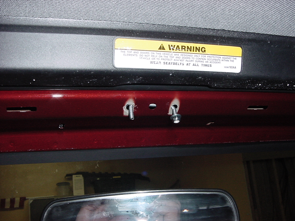
| Align the bracket horizontally and tighten down. You can see in this picture how the non-bent piece of all-thread interfered with the alignment hole. |
 |
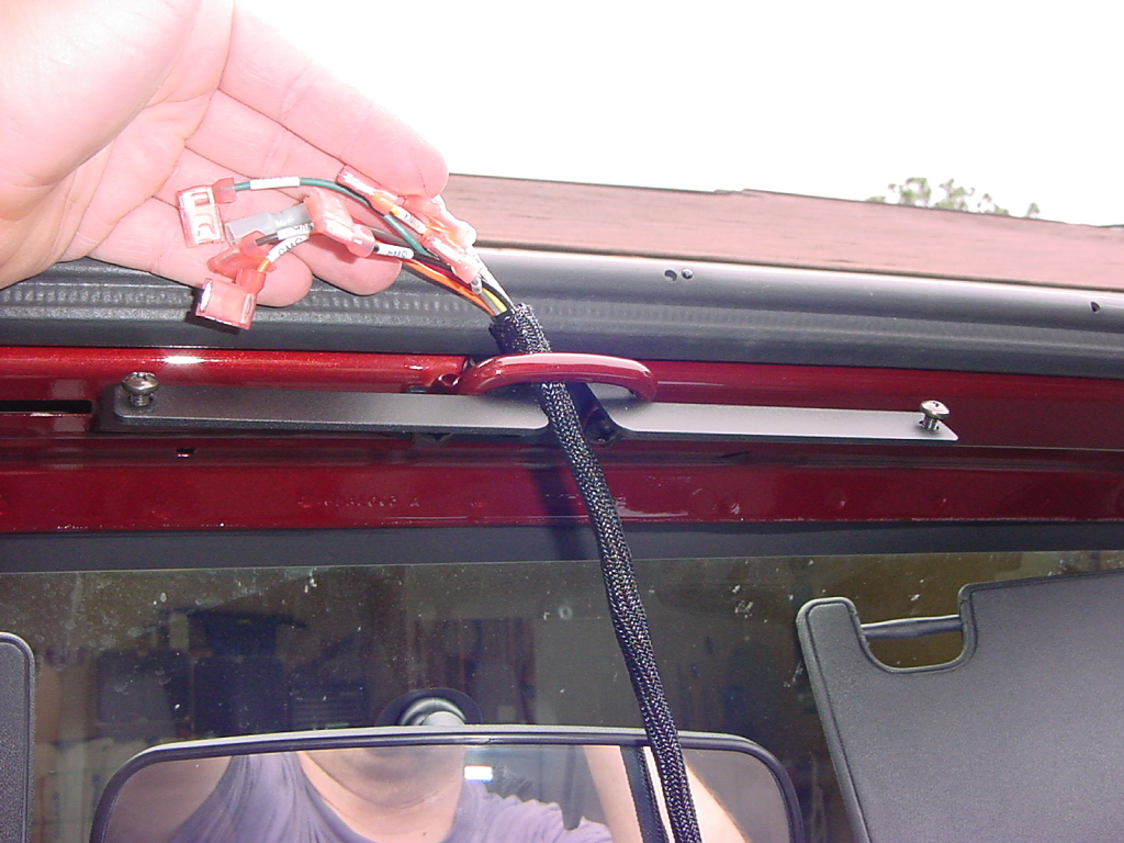
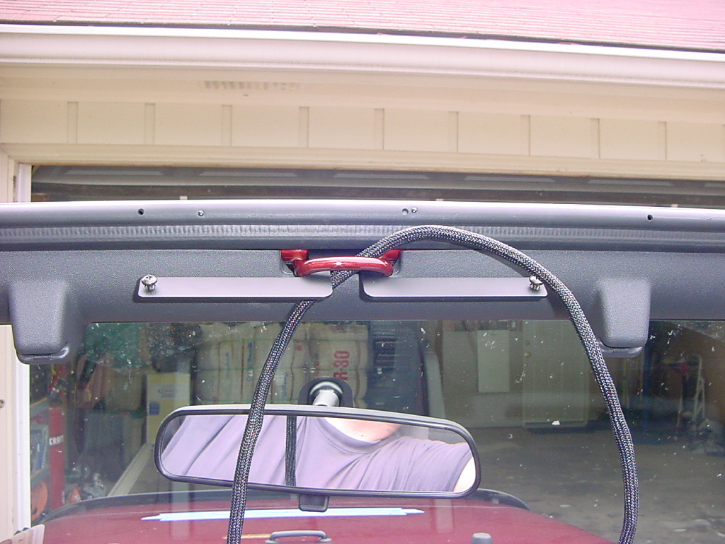
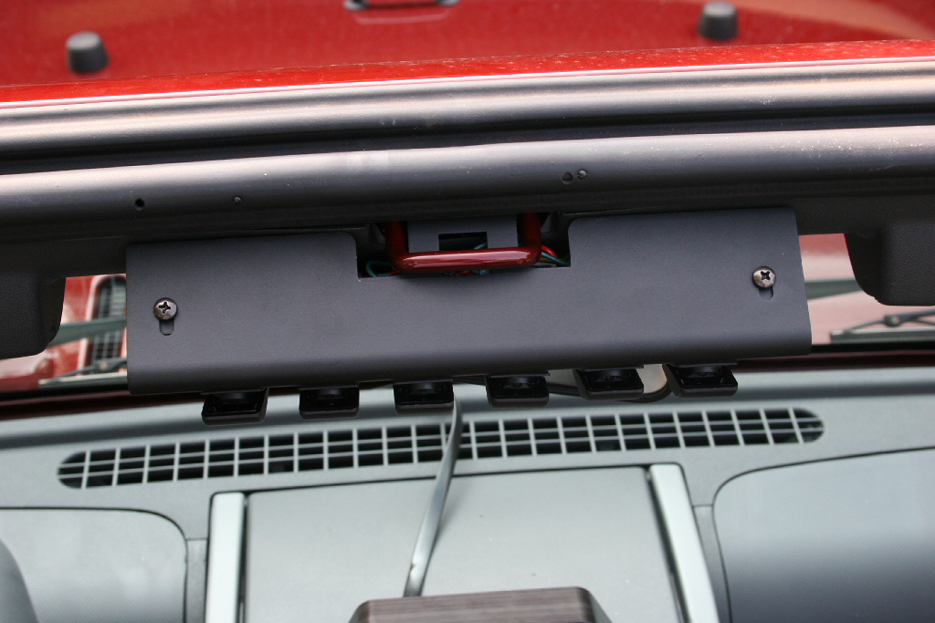
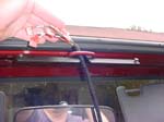
| Place the switch panel on the dash and thread the end of the wire bundle up and through the footman's loop. |
 |
| Reinstall the center section of the windshield molding. Make certain you don't catch the wire bundle while you are install the molding. |
|
|
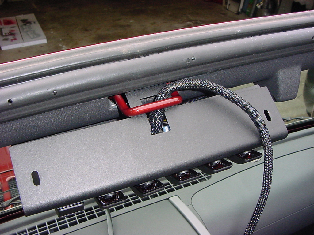
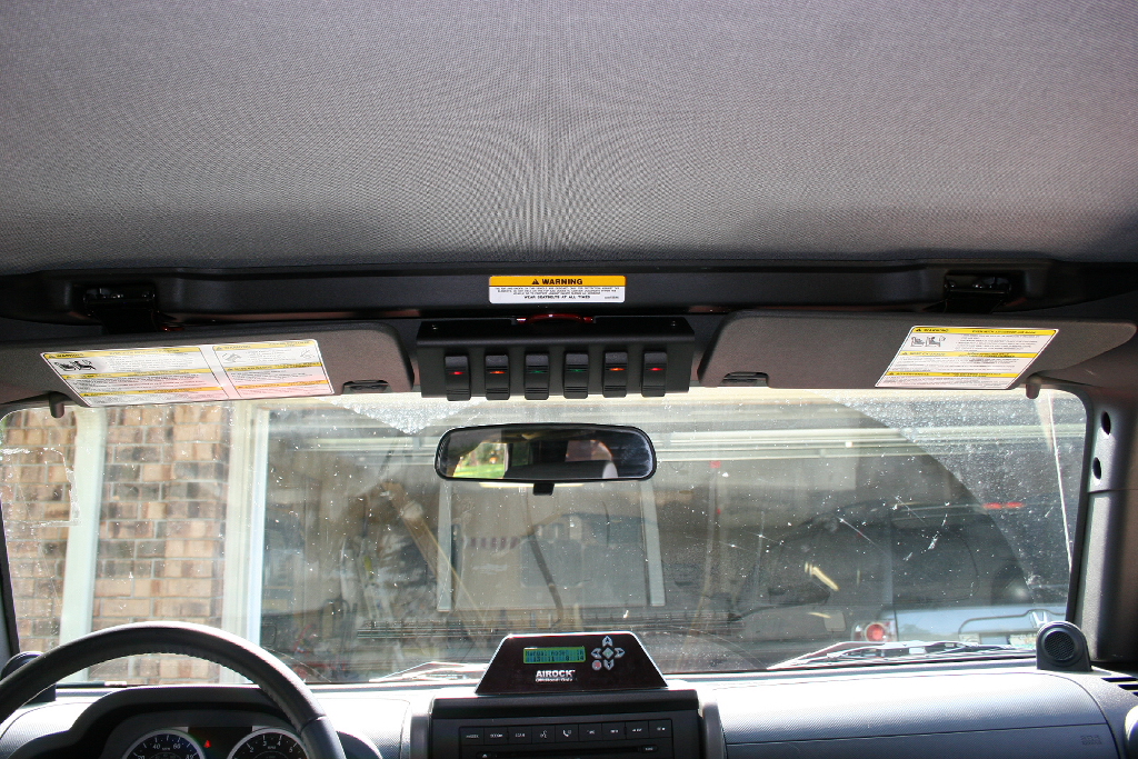
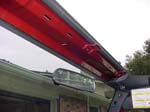
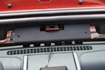
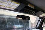
| Lift the switch pod up into place and slide it back over the switch bracket. This picture is one of the early prototypes, that illustrates how Jeep decided to change their footman's loop. The first few JK's had a footman's loop that was bent closer to the windshield. The new switch pods are cut to accommodate this. |
|
 |
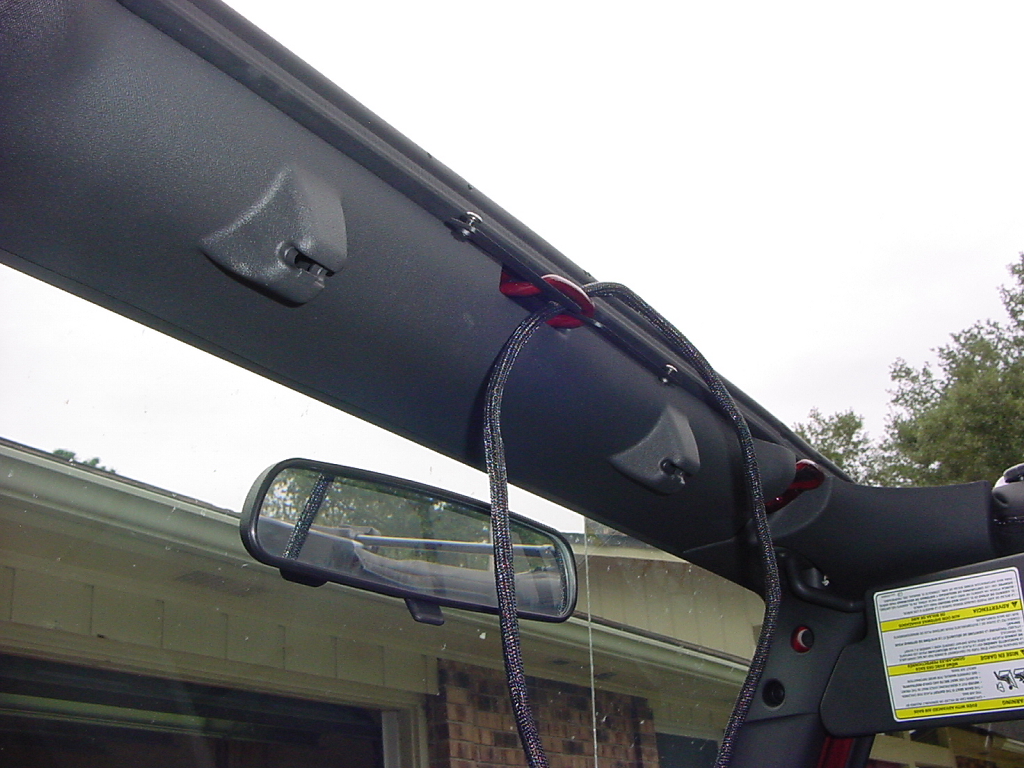
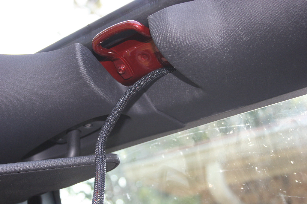
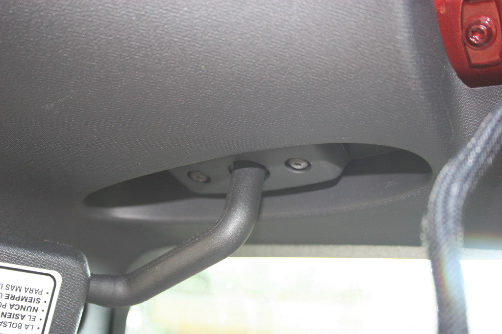
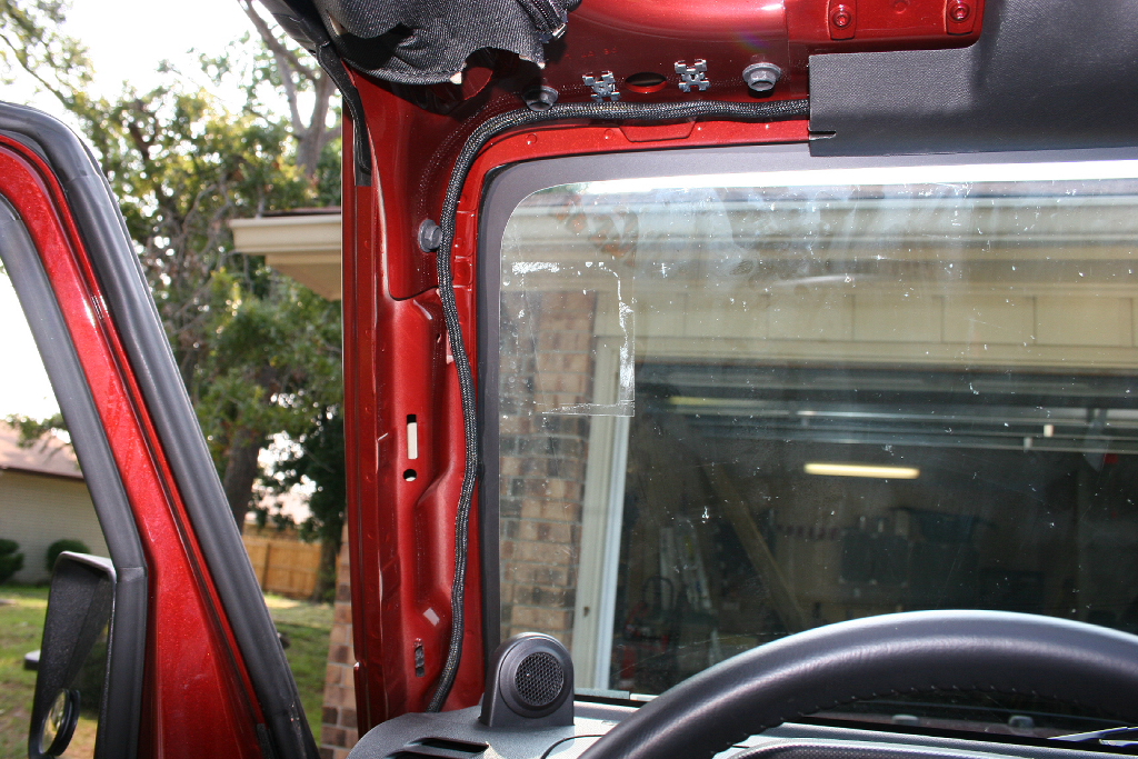
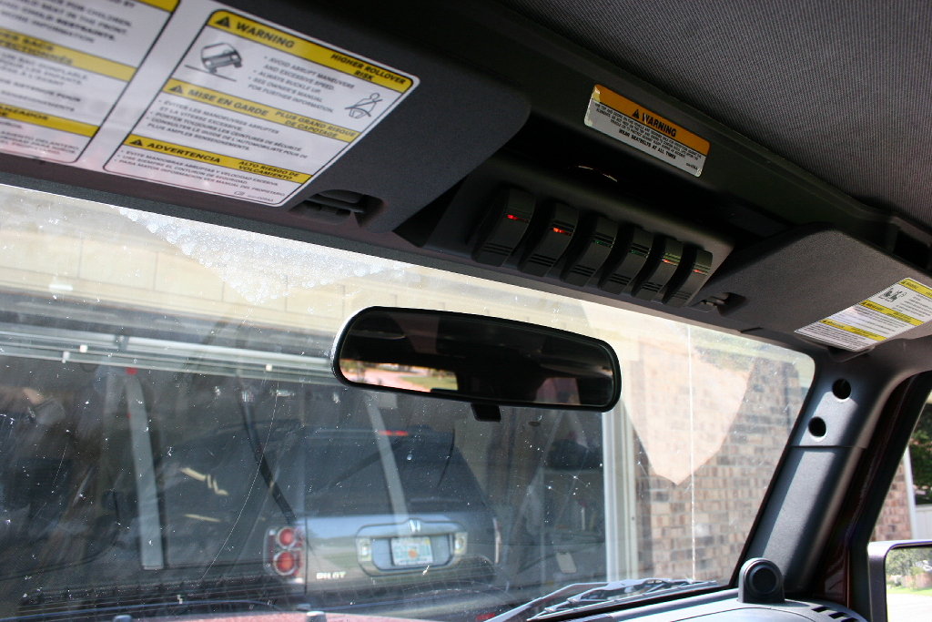
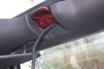
| Route the switch harness along the windshield molding. Until you get to the drivers sun visor. |
 |
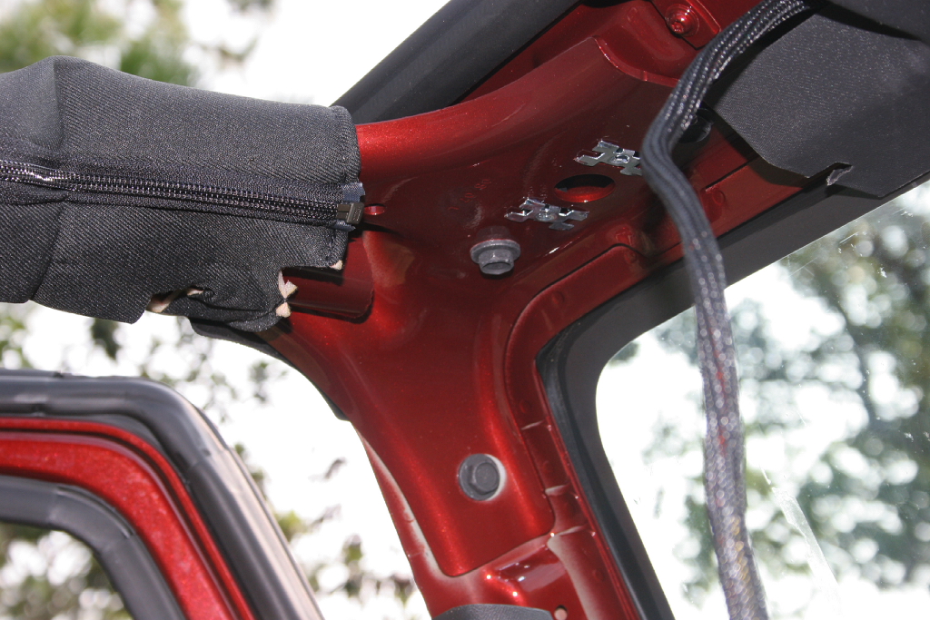
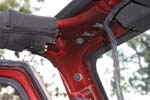
| Remove the two T-20 Torx screws holding the drivers sun visor and spacer on to the windshield frame. |
|
 |
| I decided to remove the windshield surround on the drivers side, but you don't need to do this, you can ease the wiring in behind the surround. Remove the plastic trim retainer with a phillips screwdriver. Go easy, you don't need to apply any pressure. Then pull out the retainer from the roll bar (white piece sticking up in the center picture) |
|
|
 |
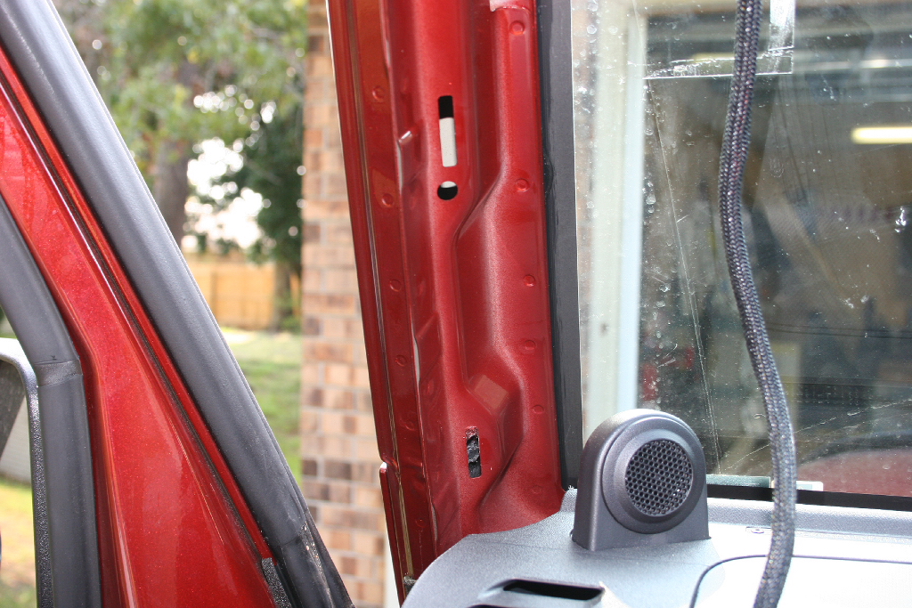
| Remove the side panel by pulling out the clips |
|
 |
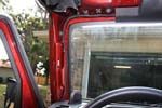
| Route the wire along the edge of the windshield and reinstall the windshield surround. |
 |
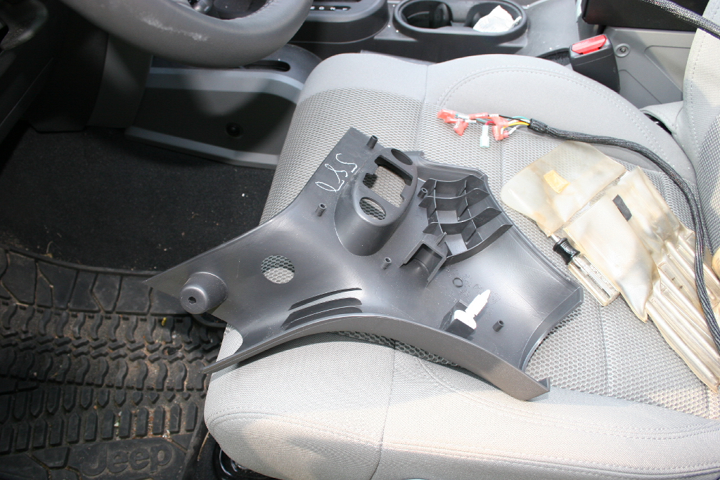
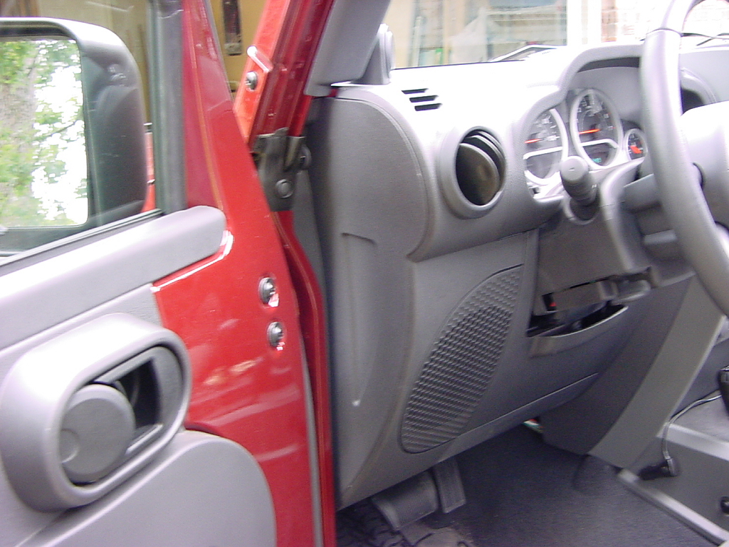
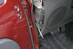
| Remove the side panel from the dash. It's just held in by some plastic tabs, and comes out easy. |
|
|
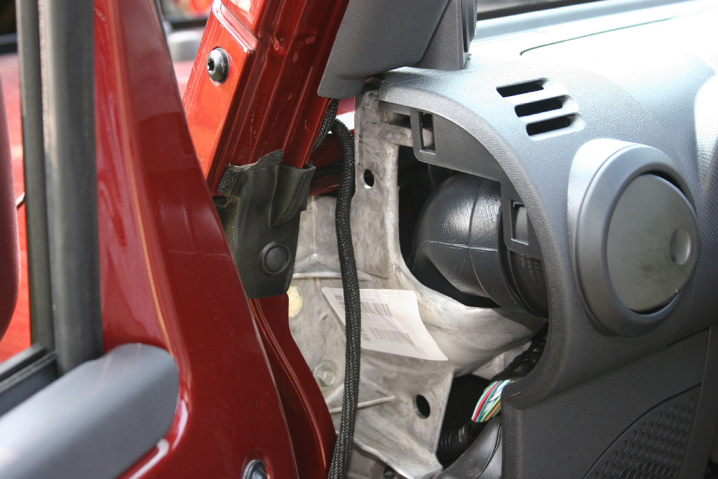
| Run the wire down along the outside edge of the dash. |
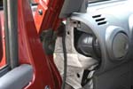 |
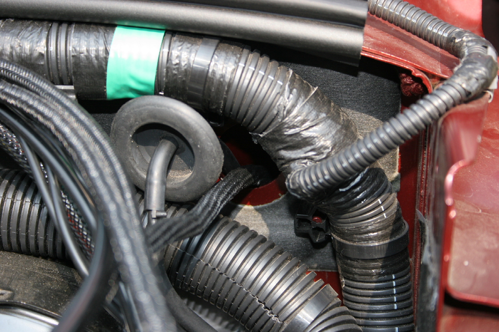
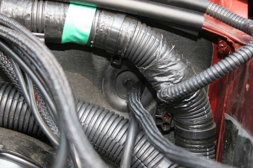
| Remove the rubber plug from the firewall side. It may have a rear washer hose running through it, so don't pull the plug out to far. |
 |
| Insert a mechanical fingers or coat hanger through the hole and into the dash area. |
|
 |
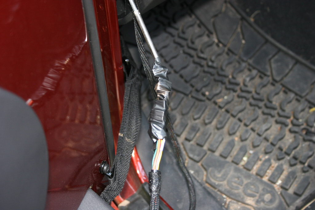
| Tape the end of the switch harness to the mechanical fingers or coat hanger and slowly pull through the firewall. |
 |
| Cut a small slit in the inside of the rubber plug and feed the switch harness through it. The ends will go through one at a time. |
|
 |
| Work the rubber plug down the switch harness until you have all of the harness available and the plug can be pushed back into the firewall. You will need enough harness to reach the computer on the drivers side. I would recommend dabbing a little silicone sealant around the wires to seal up the air gap caused by the cutting of the rubber plug. |
 |
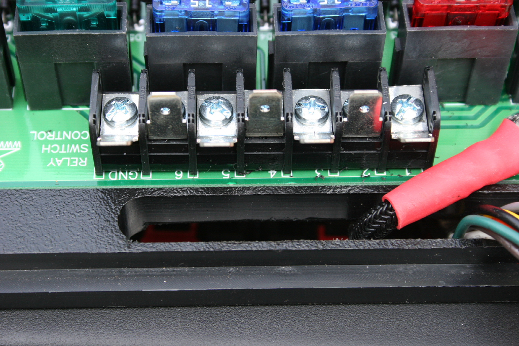
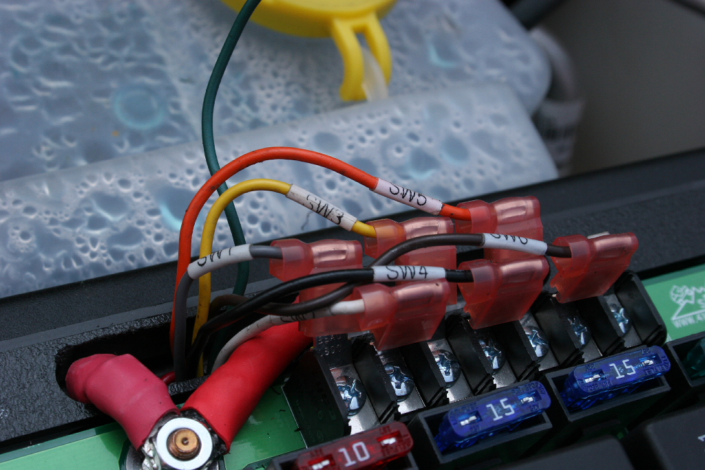
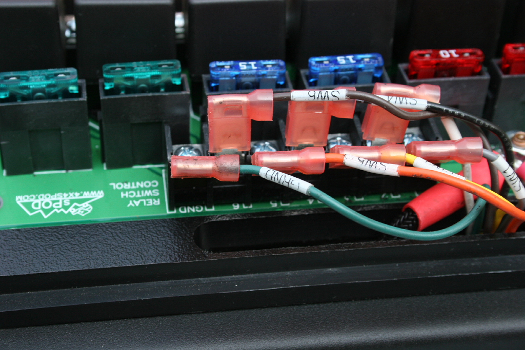
| I found it much easier to connect the switch leads to the switch block on the source prior to installing the source to it's mounting location. The leads are labeled, so all you need to do is connect them to their respective terminal. |
 |
|
 |
| The green wire goes to the ground at the end of the terminal block. |
 |
| Remove the fuse from the sources power lead to the switch harness. |
|
 |
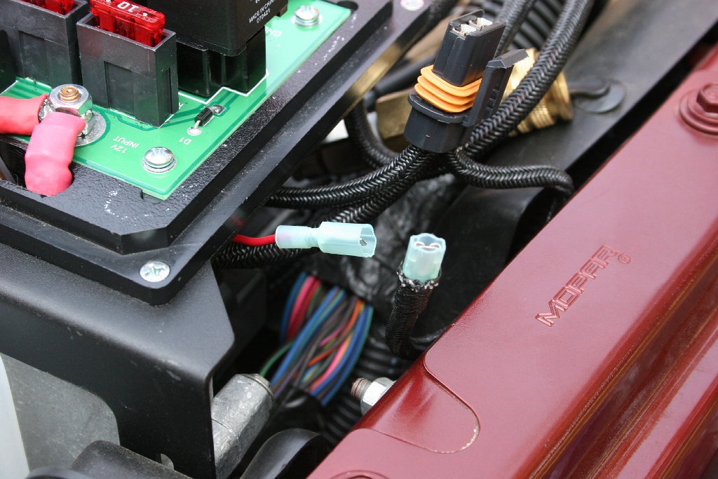
| Connect the red power lead on the switch harness to the fused power lead on the source. |
 |
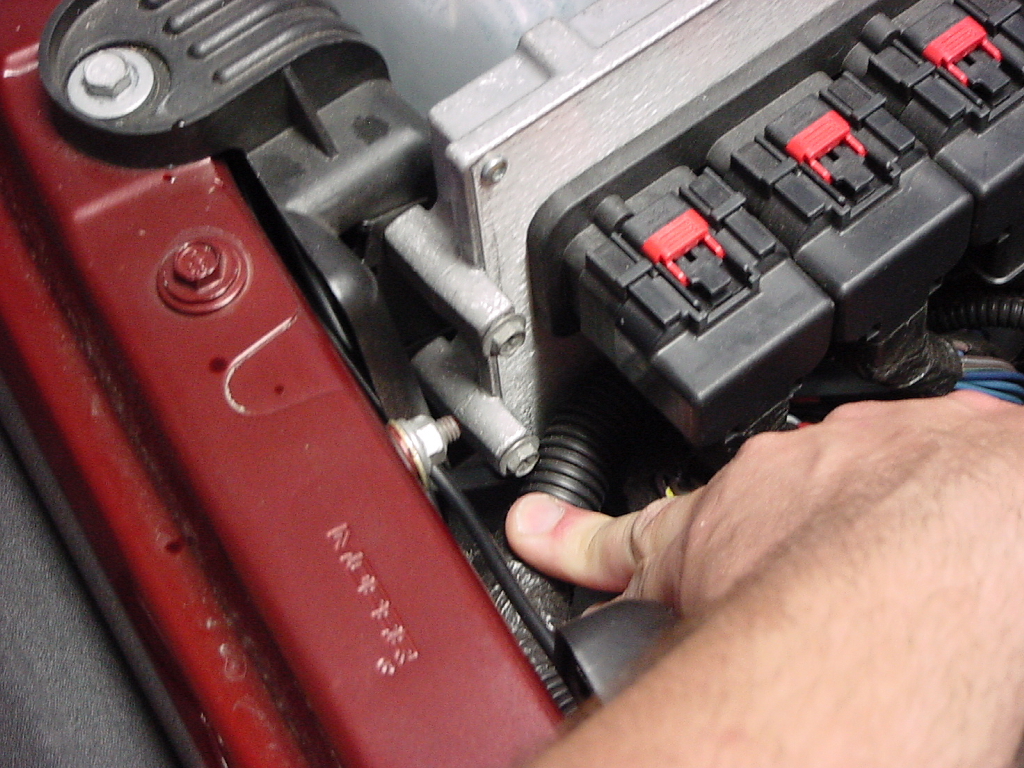
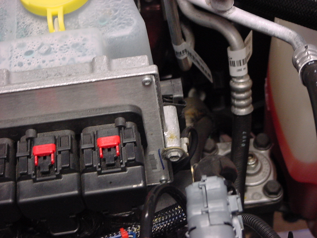
| Loosen and remove the top computer hold down bolts from each side of the computer with a 8mm socket. |
|
|
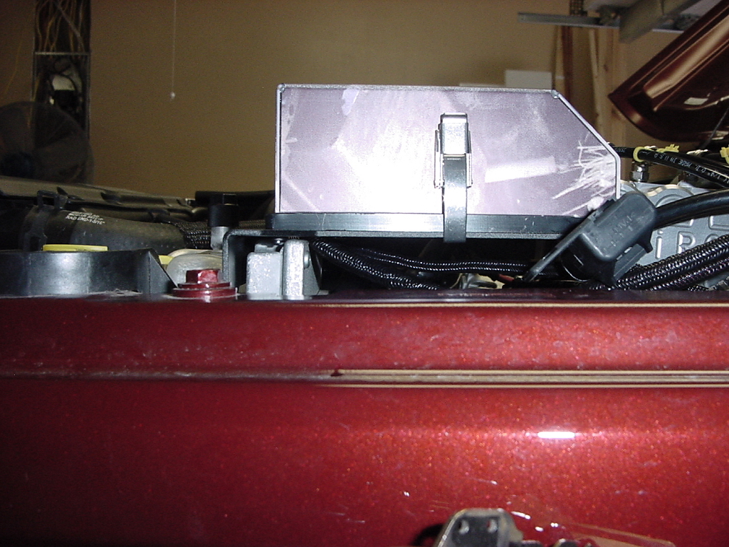
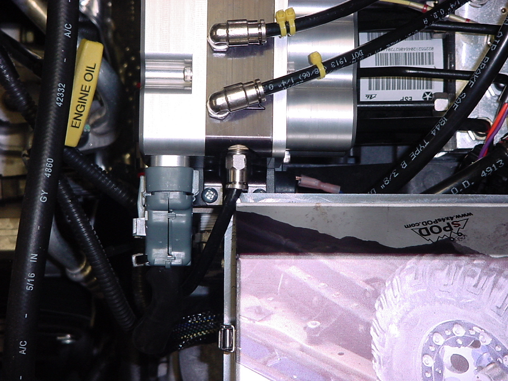
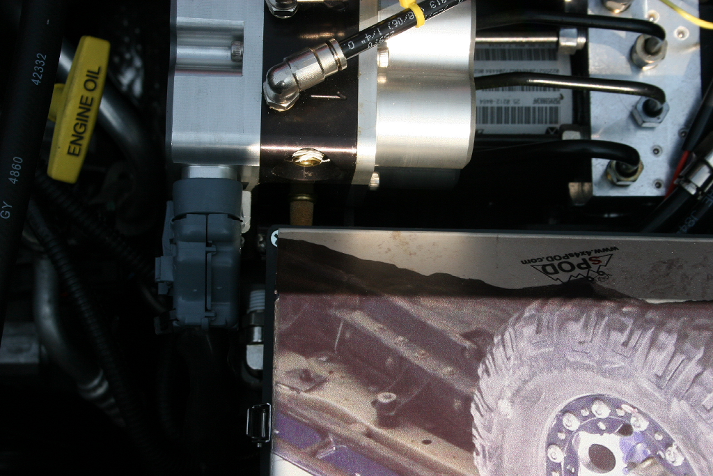
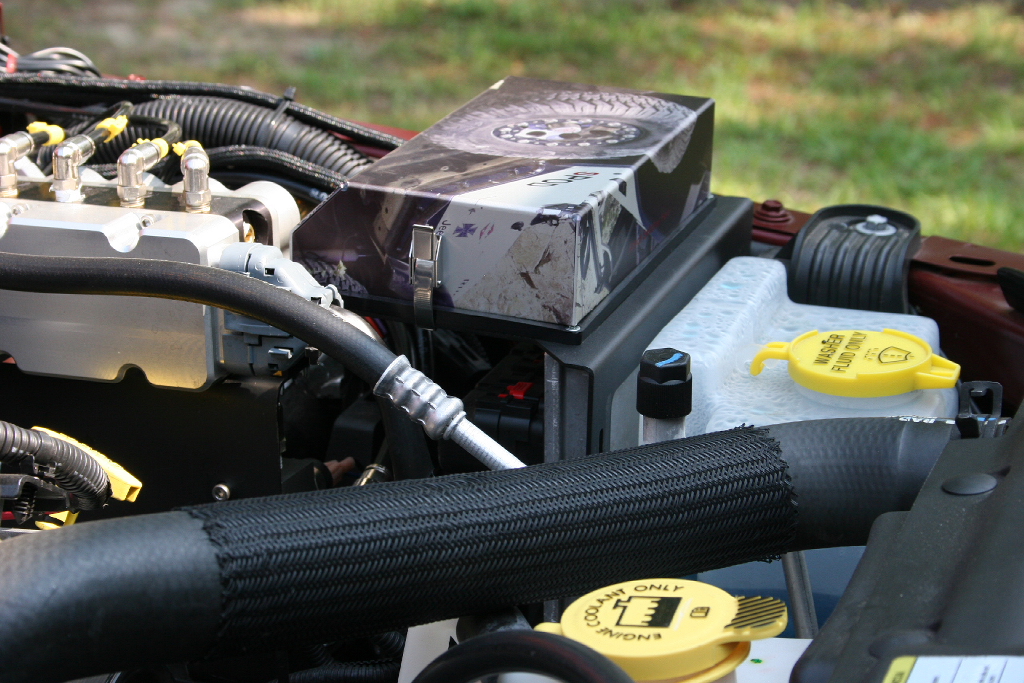
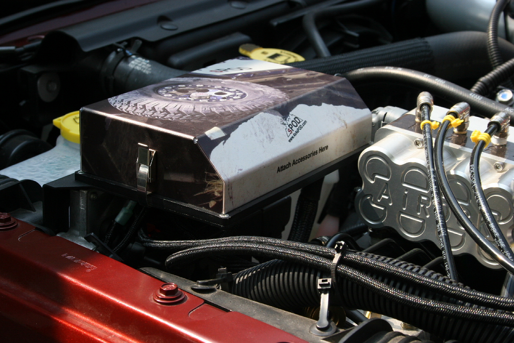
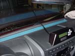
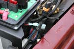
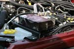
| My JK had AiROCK installed so I ran into a clearance problem with the designed mounting point of the sPOD source. I simply went up and over the computer with the mounting bracket vice mounting it to the face of the computer like designed. It still clears the underside of the hood. Note: The ACU air supply fitting needs to be swapped to the other side. |
|
|
 |
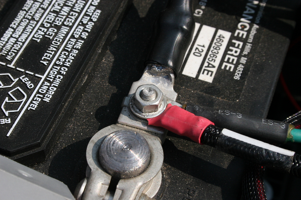
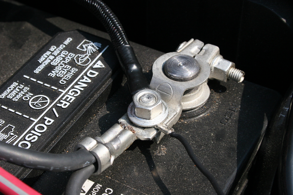
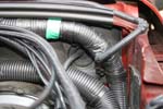
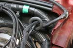
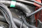
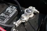
| Route the power leads along the firewall to the battery. |
| Connect the breaker'd lead to the positive terminal and the ground to the negative. |
|
 |
| The fuses are interchangeable, so you can wire in any order and just install the correct amp fuse as you need to. |
|
| Now you can wire in any accessories that you need to the provided power and ground connectors on the source. The power lead will go to the terminal marked SW1-6 and the ground lead will go to the adjacent GND terminal. |
 |
| |
| Some Pictures: |
|
|
 |
 |
|
 |