I grew tired of having to get out and disconnect my front
anti-sway bar all the time. Then came the headache of clipping it up
and out of the way. I had looked at the Currie Anti-Rock (actually
had one sitting on my workbench), but decided I didn't want to deal with
the inherent body roll that comes with it. So I kept looking.
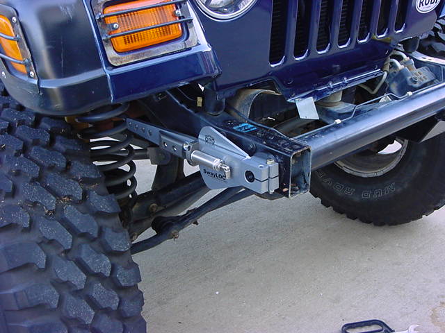
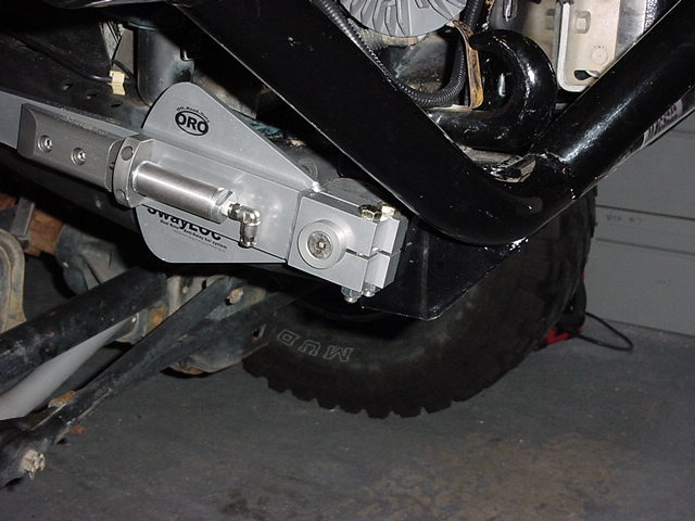
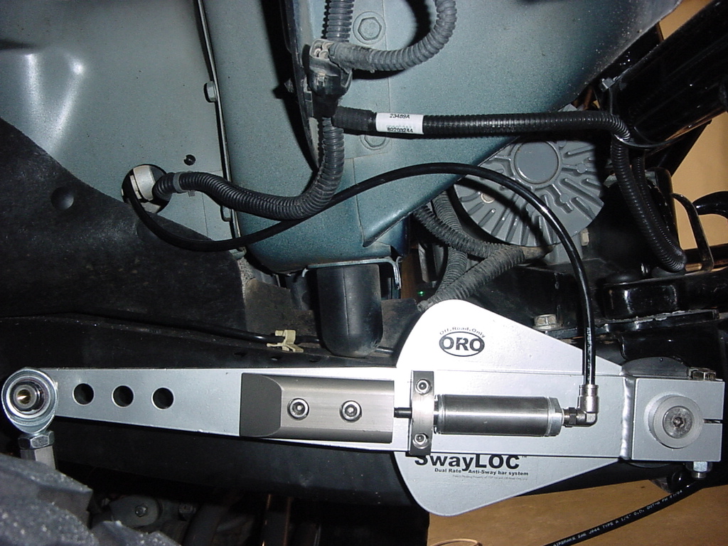
Then Off Road Only introduced their SwayLoc.
"SwayLOC is a dual rate Anti-Sway bar system that
allows the operator an easy method of changing from on road rate to off
road rate. The on road rate is softer than the OEM Anti-sway bar, this
will allow a more compliant ride on highway, as the SwayLOC will absorb
some of the jarring that may be transmitted to the vehicle thru the OEM
Anti-sway bar. The off road rate is unique in that the SwayLOC will allow
full range of articulation on most vehicles, but during this range of
movement will continue to provide resistance and will usually deliver a
more balanced feel of the vehicle."
"The transition from off road to on road is done
either by manual engagement of a lever mounted on the passenger side
control arm, or on a vehicle equipped with an on board air supply, the
actuation may be done pneumatically. The pneumatic actuation can be
operated either by an electrical switch inside the Jeep, or if the Jeep
also has an AiROCK™ air suspension system installed, then the software
in the AiROCK™ will automatically control the actuation based on the
preference of the operator."
| Installation: |
| 1. Remove the front anti-sway bar. Now if your like me you
need to remove your aftermarket bumper and winch. |
|
2. Remove the 6 T-55 Torx bolts that hold the bumper to the frame.
|
 |
|
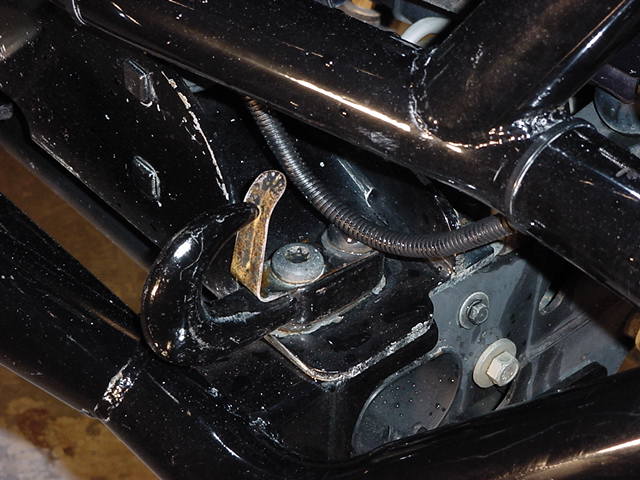
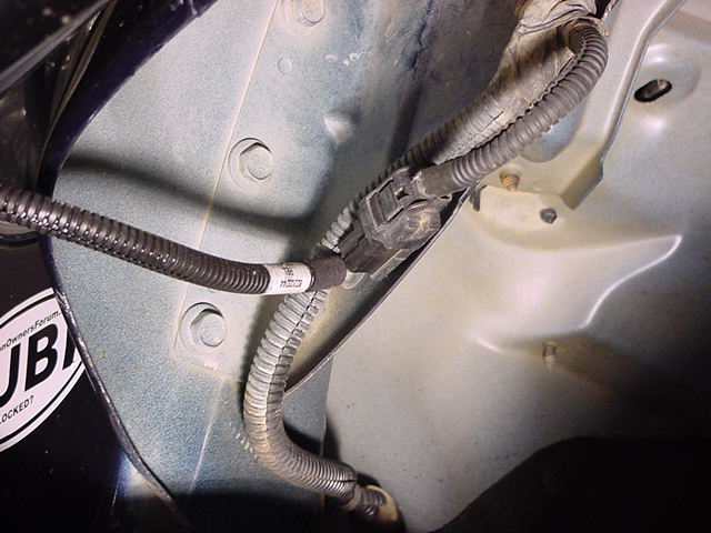
| 3. Undo the fog light lead so that you can remove the bumper. Note: Failure to unplug this will result in either bumper
coming out of hands, or wires coming out of Jeep. Just press
in on the clip and they come apart, you will need to pull the plastic
end out of the hole on under the bumper. It has a push retainer
on the clip. |
|
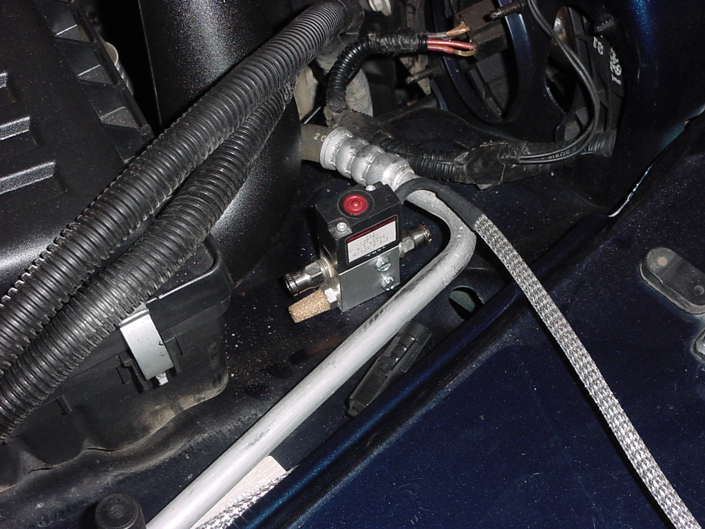
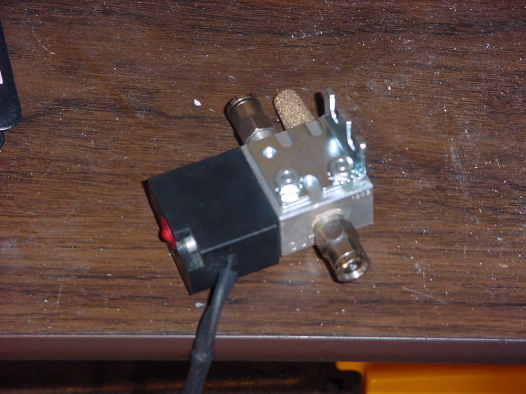
| 4.
Disconnect the winch from the battery and feed these cables back
down to the winch. See note above, remember winch is heavier
than bumper. |
|
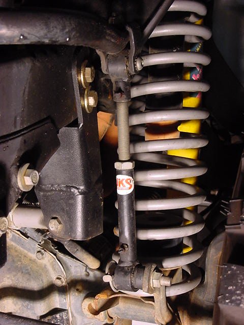
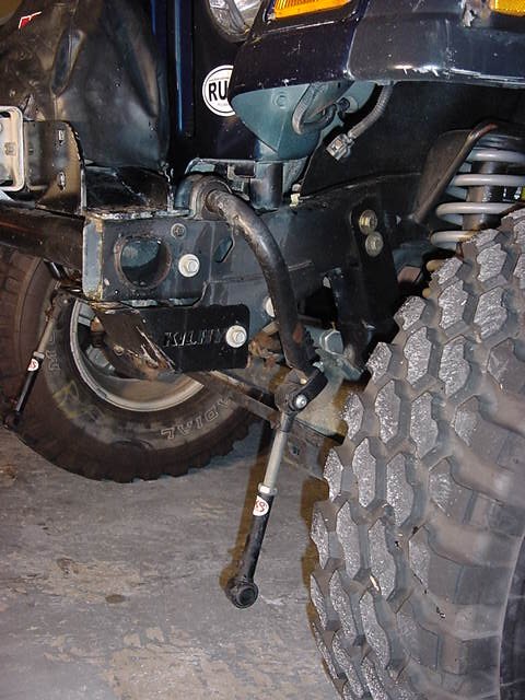
| 5. Disconnect the anti-sway bar links from the axle. If you have disco's
then just pull the pins. In my case I had JKS disco's so I
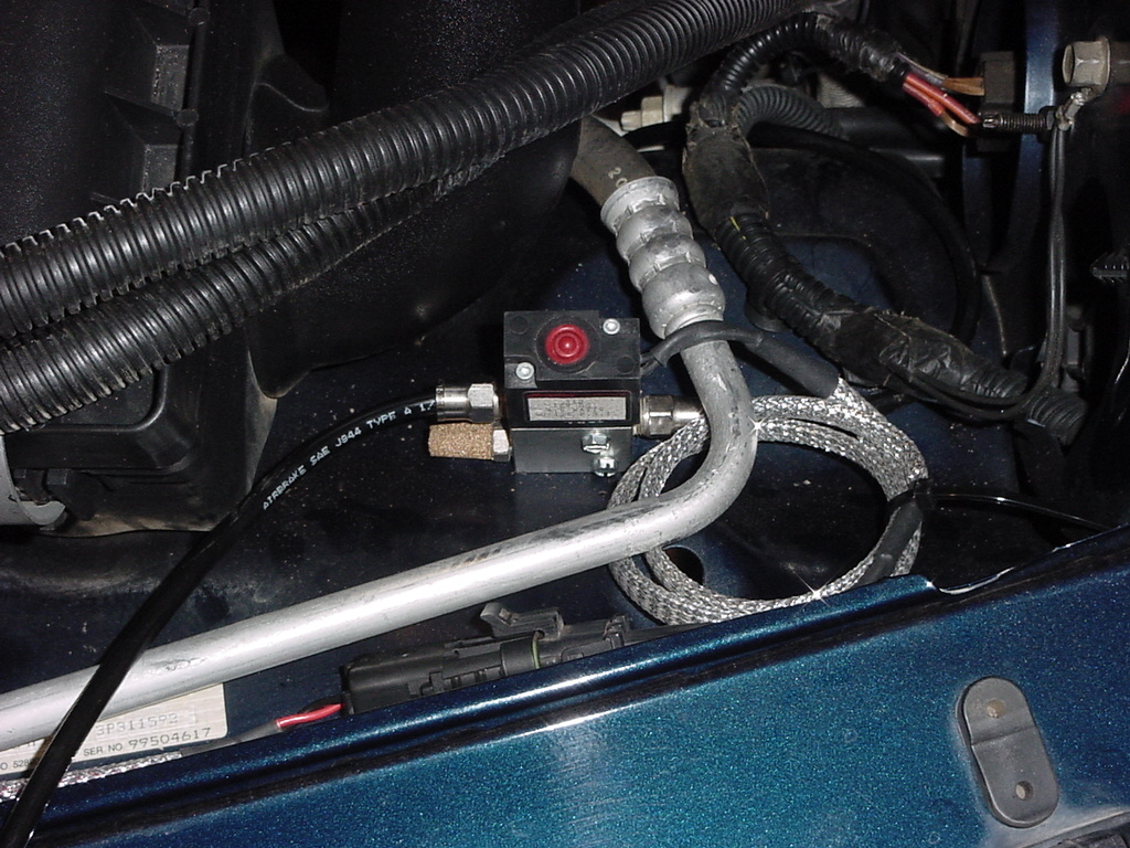
needed a 3/4" Socket to remove the lower pins. If you
still have the stock links, you will need a T-55 Torx and an 18mm
Combo wrench to remove the lower bolt. |
|
|
6. If you still have the stock cover on over the anti sway bar you
will need to remove this. Remove the 2 bolts on either side
with a 10mm socket.
|
|
|
7. Remove the 4 bolts holding the anti-sway bar to the frame.
This requires a 15mm socket and a short extension. I recommend
using a rag when you remove the bolt by the grill so you don't damage
the paint. |
|
|
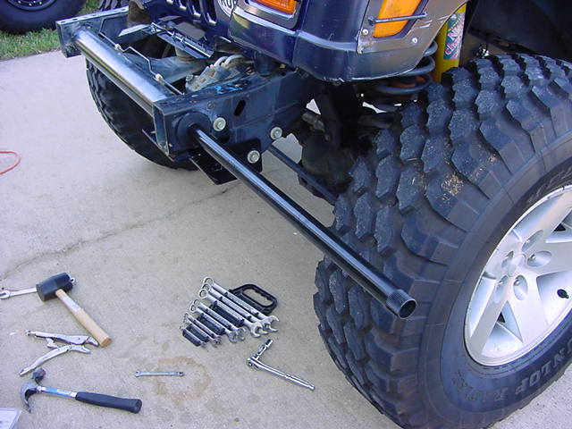
8. Slid the entire bar assembly forward and out from the Jeep. |
 |
|
|
9. Take a moment to clean off the debris that has accumulated on the
front frame.
|
|
|
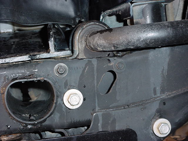
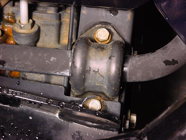
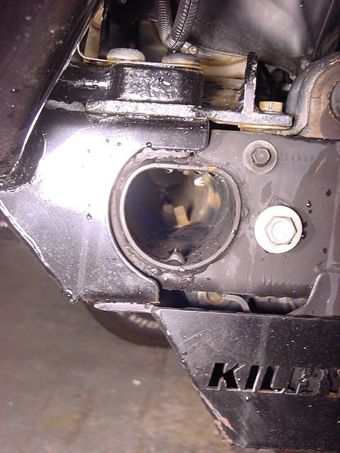
10. Take a look inside and at the front cross tube. Make certain
nothing is sticking to far into the tube. I used the simple
rule of if I could see it above the dimples I needed to cut it down
a little. I also had a bad weld slag on the driver side that
I needed to cut off and grind down. Take a moment to paint
any areas that you ground.
|
|
|
|
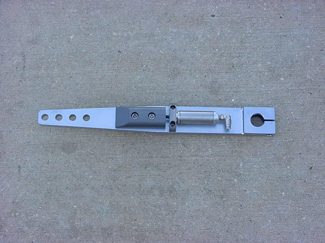
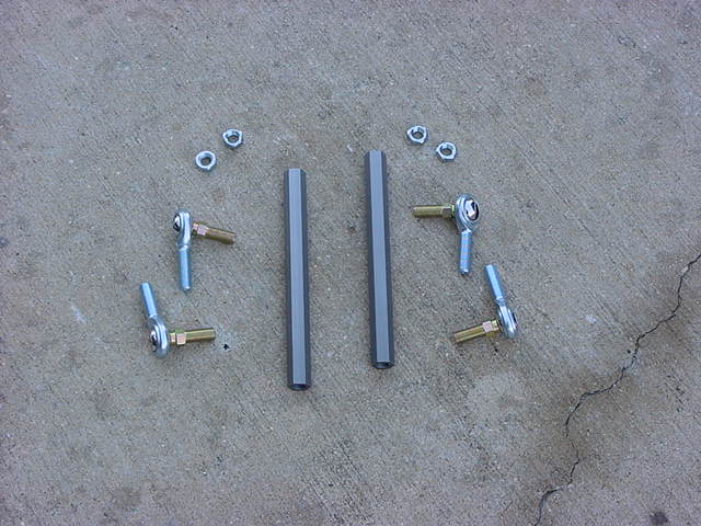
Here
is the parts that you get with the AiROCK, or OBA kit. Everything
comes nicely packed and labeled. Quality control is wonderful.
The directions for this kit are awesome. This write up incorporates
those directions. |
|
|
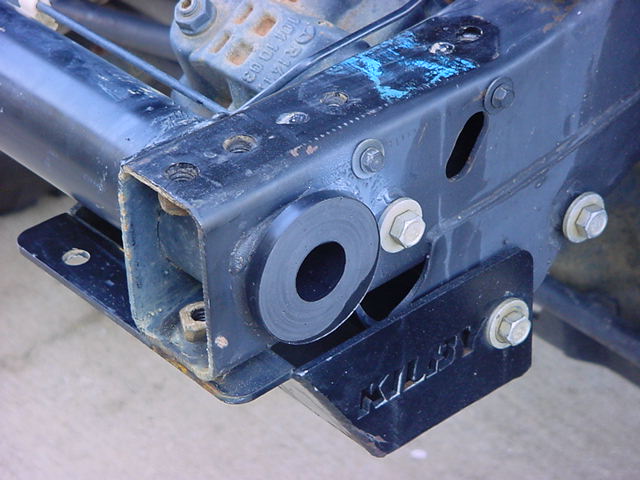
11. Insert one of the frame bushings into the D shaped tube in the frame.
Drive the bushing fully into place using a wooden block and mallet
if necessary. |
|
|
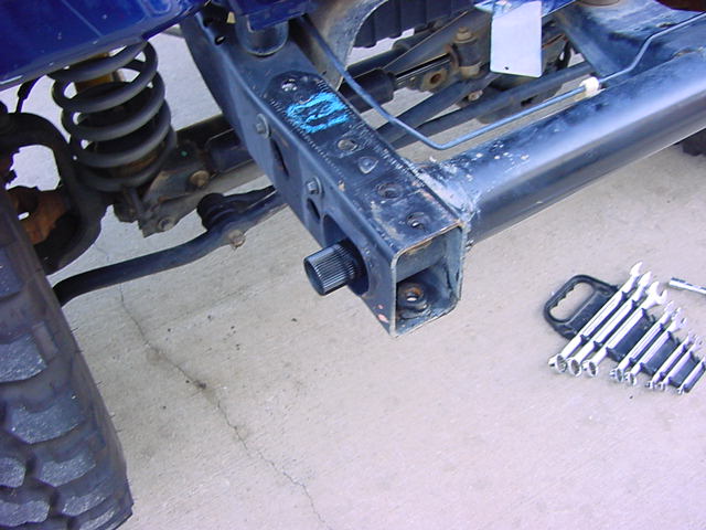
12. Wipe down the torsion tube with Silicone lube and insert tube
in bushing. The directions state an alternate way of
doing this, which is to insert the bushing onto the torsion tube
leaving 3/4" extended out. This actually works the best.
I used a 1 1/4" socket to drive the bushing into the frame. |
|
|
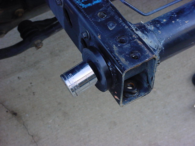
13. Once tube is thru the frame rail, install opposite frame bushing
and drive into place with large socket to fit over tube if necessary.
I used a 1 1/4" Socket. If you drive the torsion tube
out the other side, just tap it back in. |
 |
 |
|
14. Center the Torsion tube in the frame side to side, with approximately
3/4" of the tube extending thru the driver side bushing when
it is fully seated up to the frame cross member.
|
|
|
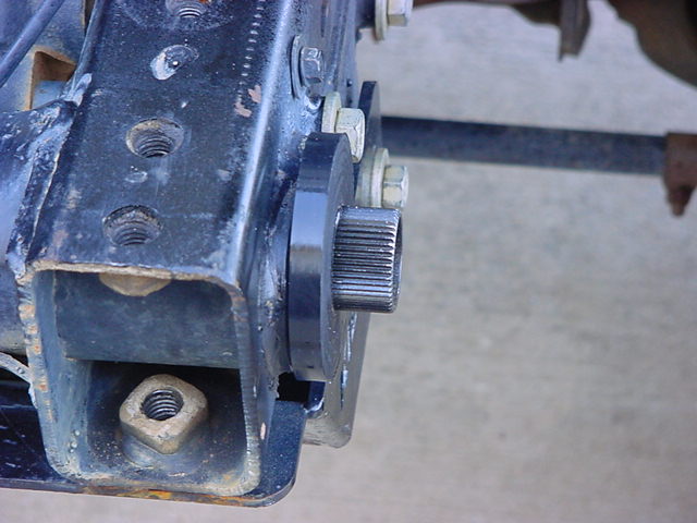
15. Check the splines of the short passenger inner arm to make certain
that they are clear of any debris. This will prevent you from
being able to install the arm smoothly. Install the short
passenger inner arm on the torsion tube, place arm so that the latching
point is horizontal to the ground and ensure that the 1/4"
wide web is offset to the outside of the vehicle. I
coated the splines with silicone lube and slid the arm over them.
I used the mallet to gently persuade the arm onto the torsion tube.
(Note: An easier way
is to allow the arm to hang straight down.)
|
|
|
16. The arm should sit flush against with the torsion tube, double
check the other side to make certain that the tube and bushing didn't
slid out. There should still be 3/4" of the tube extending
out. |
|
|
17. Install the inner arm so that the large Pedal is towards the outside
(or the side with the stickers on it goes out). The inner
arm web and splined hub should be flat on the side that mates the
outer arm. Install one 3/8 x 2 �” bolt thru the cross-hole, install
3/8 lock nut and only snug the nut and bolt at this time. This
needs a 9/16" socket and combo wrench |
 |
|
|
18. Install the Driver side arm (this arm has two splined hubs welded
to it and does not have the fancy latch assembly). Check the
splined section for any debris and clean it out with a scribe or
wire brush before you try to install this arm.
|
|
| 19. The arm should be positioned at the same angle as the latching
notch on the passenger inner arm when you install it.
I couldn't get it quite perfectly parallel, but really close.
The torsion tube should insert fully to make contact with the smaller
diameter hub. If it doesn't go on this far, double check both
bushings and the passenger side. I needed to hold the passenger
side short arm in and tap the drive side arm on the rest of the way
with a mallet. Install one 3/8 x 2 �” bolt thru the cross-hole
on the inner hub, install 3/8 lock nut and only snug the nut and bolt
at this time. This needs a 9/16" socket and combo wrench.
(Note: An easier way
is to allow the arm to hang straight down.) |
|
| 20. Insert the 1" splined torsion shaft inside the torsion tube
from the passenger side. |
|
| 21. Rotate and engage the splines on the drivers arm, insert fully.
Install one 3/8 x 2 �” bolt thru the cross-hole on the outer hub,
install 3/8 lock nut and only snug the nut and bolt at this time.
This needs a 9/16" socket and combo wrench. |
|
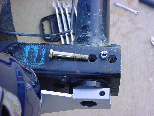
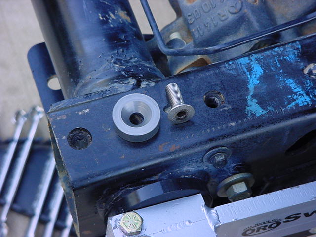
| 22. Assemble the aluminum washer and mating flathead cap screw and
attach to the center torsion bar on the drivers side, snug but do
not tighten yet. This requires a 7/32" Allen Wrench. |
 |
|
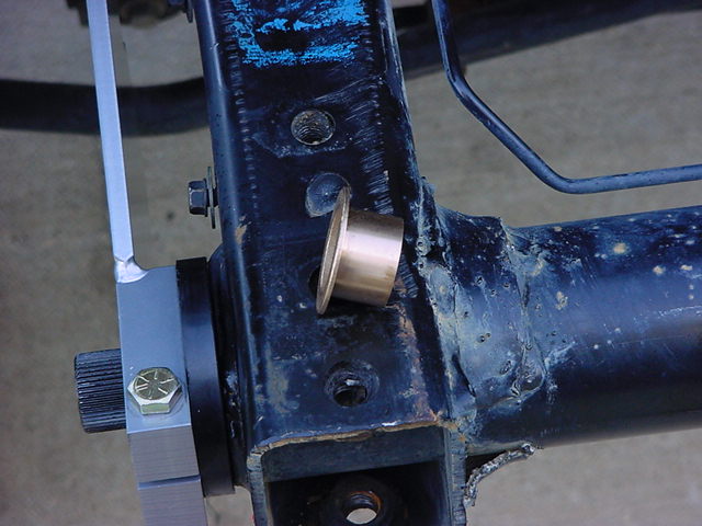
| 23. Insert the brass bushing on passenger side between the inner and
outer torsion bars. |
 |
|
| 24. the shoulder on the bushing should rest against the inner and outer
arm with the sleeve of the bushing inserted inside the tubular torsion
bar. I used a 1 1/8" Socket to tap this in. Double
check the Driver Side to make certain you didn't drive the arm out
at all. |
|
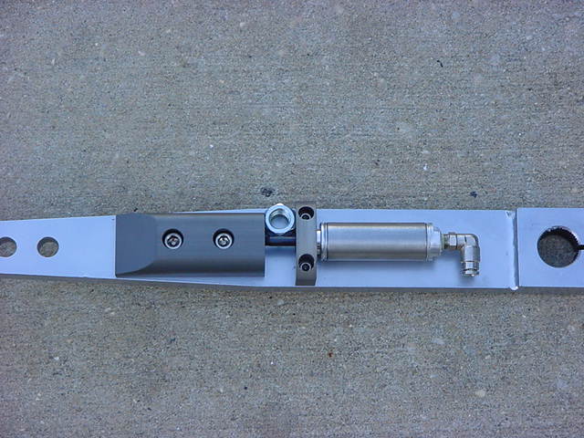
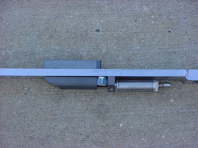
| 25. Locate the arm with the air cylinder and latch and one of the �” Nylock
nuts. |
|
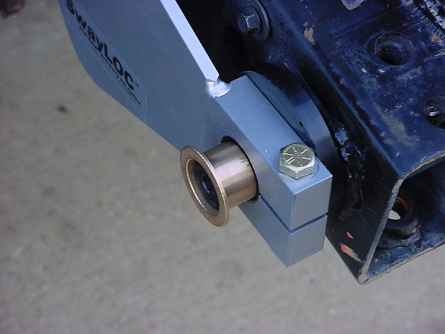
| 26.
Slide the latch assembly away from the air cylinder, insert the Nylock
nut as shown. It should be fairly easy to move, but if not use
a screwdriver to gently pry the latch away from the bracket holding
the air cylinder. I suggest putting a rag around the screwdriver
and being careful of the small shaft from the air cylinder.
This will allow you to install the arm onto the Passenger Side. |
 |
|
| 27. Position the arm at the same angle as the short arm and the driver
side arms. I was unable to do this. I was either up just
slightly from the latch point, or down just slightly from the latch
point. Almost as if it was cut just 1/2 spline off on rotation.
Not bad in my book. Remember we are trying to line up 4 pieces
on 2 different shafts. The distance off equaled 1/2 of the latching
device. Install one 3/8 x 2 �” bolt thru the cross-hole on the
outer hub, install 3/8 lock nut and only snug the nut and bolt at
this time. This needs a 9/16" socket and combo wrench.
(Note: An easier way
is to allow the arm to hang straight down.) |
|
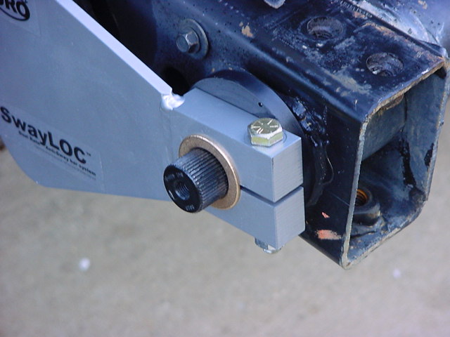
| 28. Once the arm is fully seated, assemble the aluminum washer and mating
flathead cap screw and attach to the center torsion bar on the passenger
side, snug but do not tighten yet. |
|
|
| 29. Remove both of the aluminum washer and mating flathead cap screws
and check for full insertion of inner torsion bar. If adequate, the
bar should be flush on one side and less than the thickness of a dime
short on the opposite. If the torsion bar appears to be too short,
then check to make certain that the bushings are fully seated in the
frame, and that the inner arms are fully seated against the bushings.
Reinstalling the aluminum washer and flat head cap screw, loosening
the 3/8” cross bolts and then tightening the flat head screws may
help to snug the arms together, but if the bushings need to go in
farther, it may be necessary to remove the arms and drive the bushings
into the frame with a block of wood and a mallet. I played around
with mine since I was out the thickness of a dime on both sides.
In the end it was either clamp this baby together with my hi-lift
jack or just leave it. I just centered the torsion shaft. |
| 30. Remove one aluminum washer and flat head cap screw at at time.
Place a single drop of Locktite on each bolt and reinstall. |
| 31. Now go thru and tighten each of the 3/8” bolts that hold the arms
to the torsion bars. Torque each of the 3/8” bolts to 40ft-lbs.
Remember to torque the nut, not the bolt |
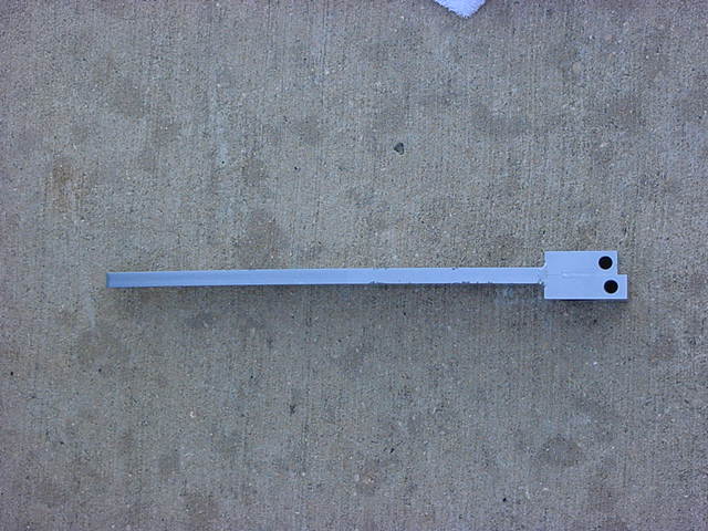
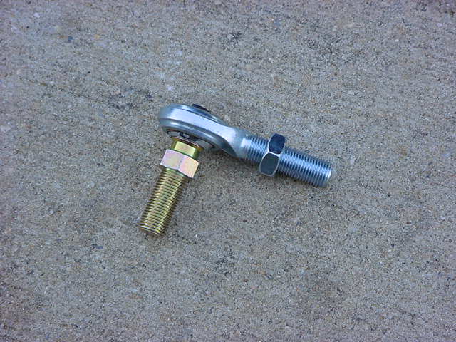
| 32. Assemble the Linkage assemblies. |
|
| 33. Be sure to insert one jam nut on each rod end before engaging the
rod end in the hex aluminum housing. The Jam Nut requires a
3/4" Open end Wrench and so does the aluminum housing.
So if you don't have a second 3/4" wrench, a 19mm will work. |
|
| Note
on adjusting Links: The links should be adjusted so that
the arms do not limit the extension of the front suspension. It is
imperative that the suspension reaches full extension before the links
limit the droop, otherwise damage to the SwayLOC may occur as the
arms will rotate under and forward. Verify at full compression the
links do not make contact with the Jeep inner fender area. Measure
the distance between bump stop and the contact point and figure that
as the approximate up travel on the arms. Do not forget to add for
the squish of the bump stop. |
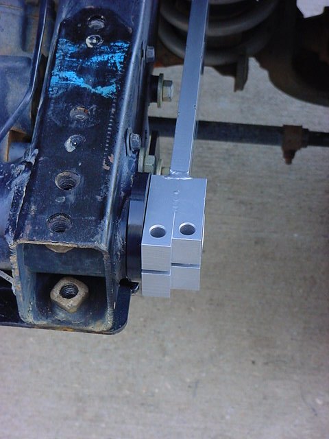
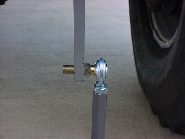
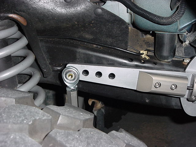
| 34. Install links on the SwayLOC. Install link on the outside of
the arms. Install 1/2" Nylock nut. You will need 3/4"
Socket and a 5/8" Combo Wrench. You will notice that the
SwayLOC has 4 holes in it. This is for adjusting the ride.
The closer to the front, the stiffer the ride.
|
 |
|
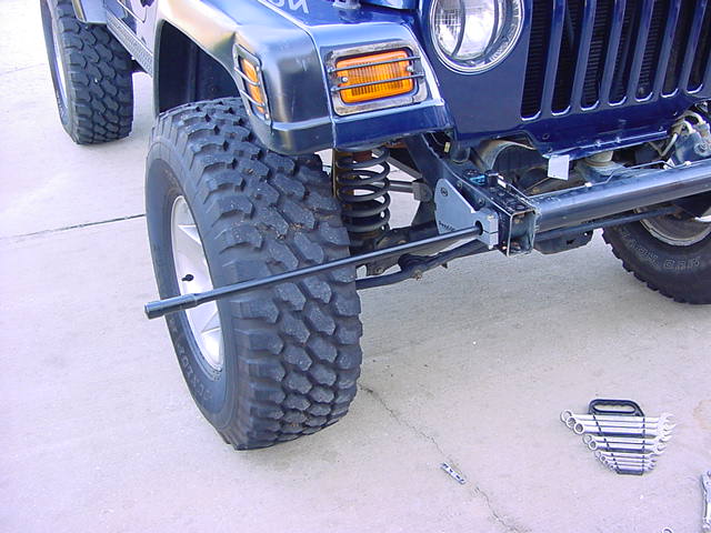
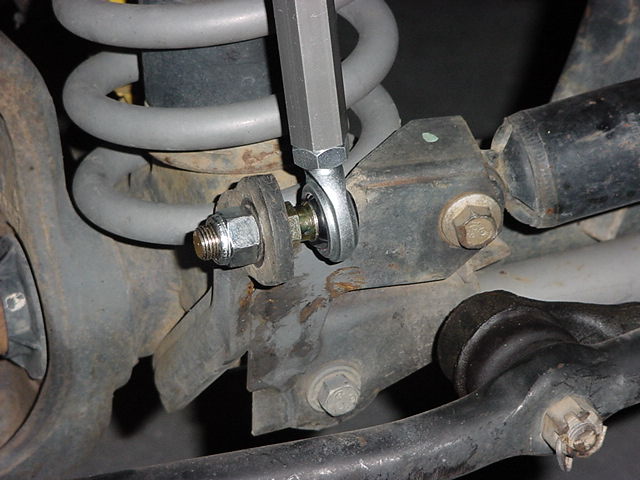
| 35. Install link on the axle. These go in the in side of the axle
mount. If you can't seem to find that missing 1/2" Nylock
Nut, look in the passenger side arm, it's in the latch assembly. |
|
| 36. Now since I did not have AiROCK installed I needed to do the install
for OnBoard Air. This would allow the SwayLOC to be switch controlled
from inside the cab. |
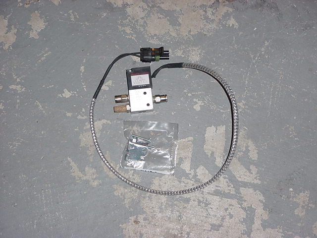
| 37. Install the solenoid assembly in any convenient location under the
hood. The solenoid may be placed anywhere, in any position,
only limited by the length of the harness to the red rocker switch. |
 |
|
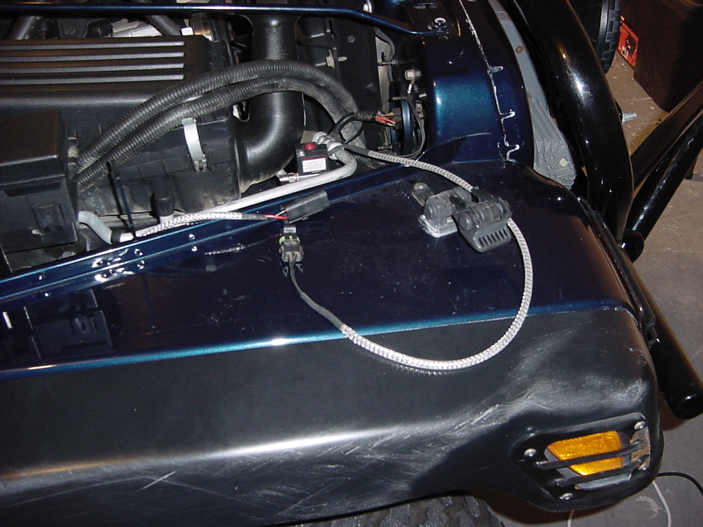
| 38. I decided that the flat spot in front of the air cleaner would be
a perfect spot for the Solenoid to be mounted. You will use a 1/4"
socket to drive in the self tapping screws to hold the bracket on
to the fender well. |
 |
| 39. I mounted the bracket to the back of the Solenoid. You will need either
a 1/4" and 5/16" combo wrench or a flat tip screwdriver
and a 5/16" combo wrench. |
 |
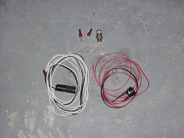
| 40. Converting over to AiROCK, or installing with AiROCK is simple.
Just replace the switch wire with the AiROCK harness. Then connect
into the AiROCK system with it. |
|
| 41. Connect the SwayLOC solenoid to the AiROCK cable. |
 |
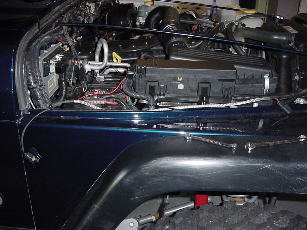
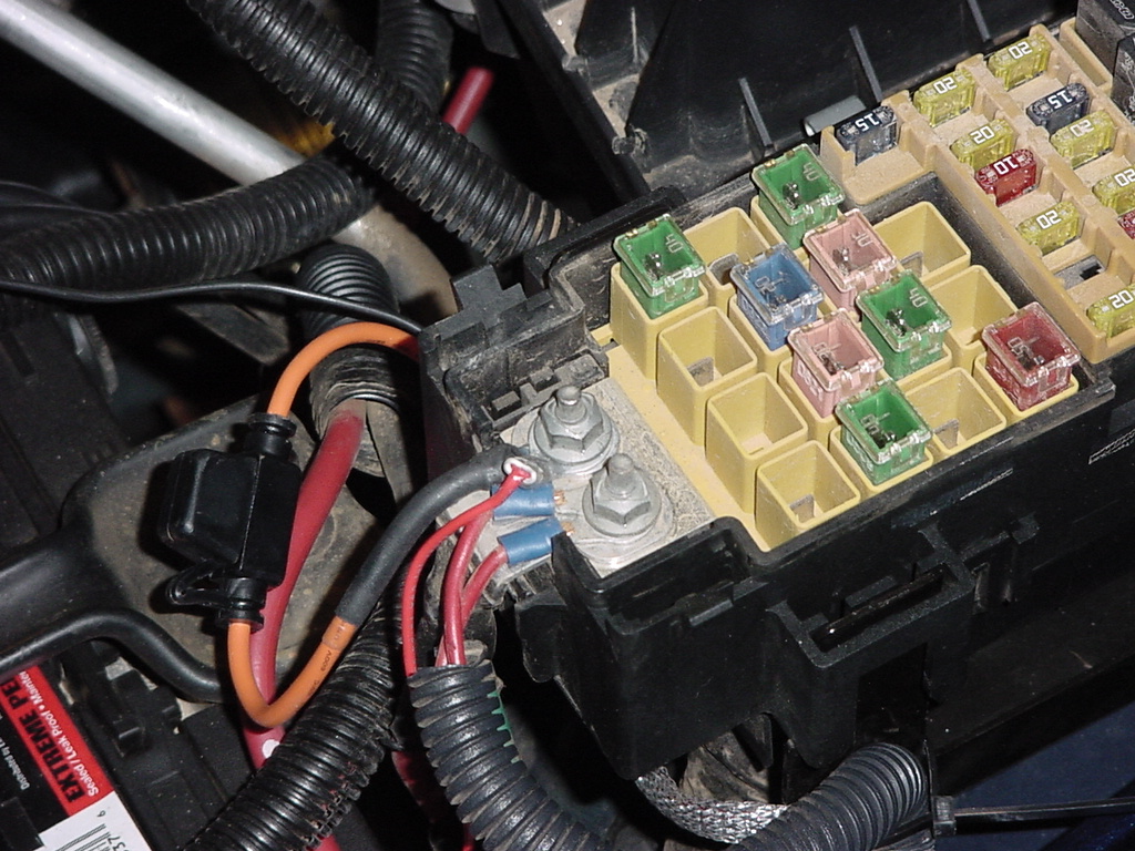
| 42. Route the wire along the side of the fuse box. |
 |
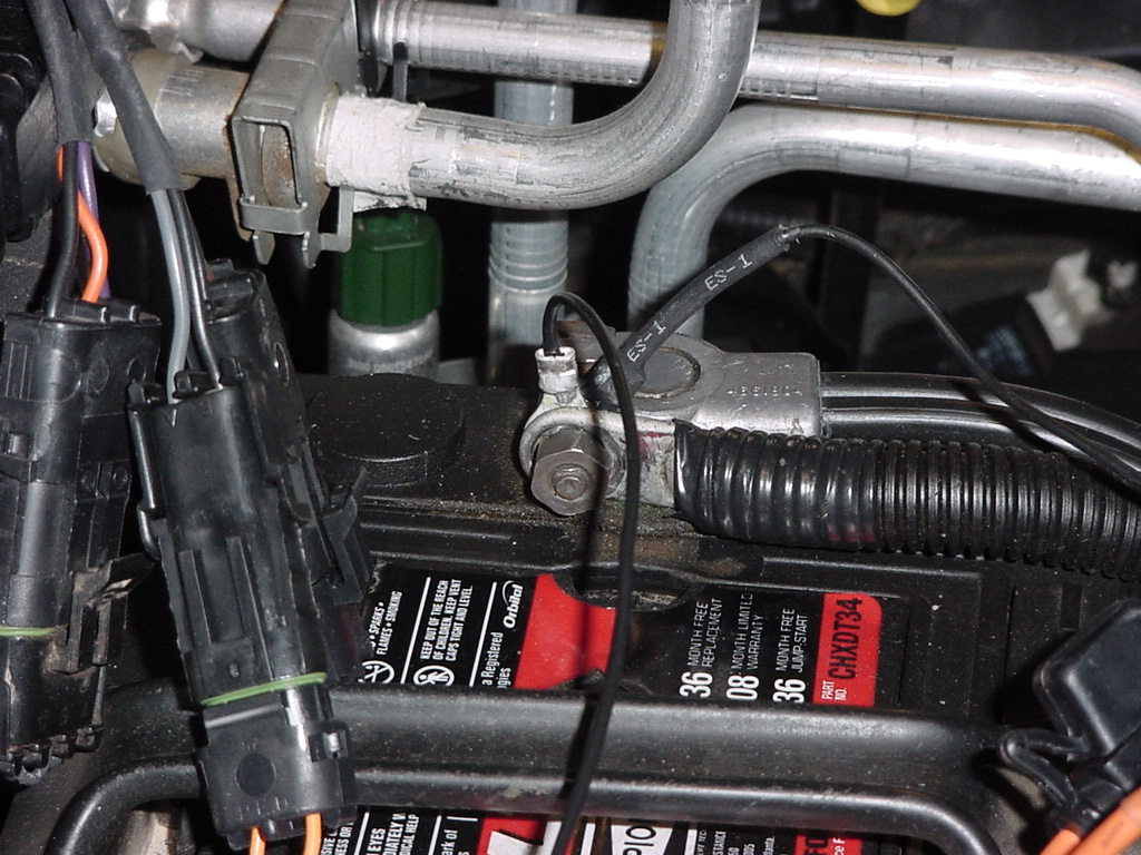
| 43. Connect the
power and ground wire to the fuse box and a convenient ground. I choose
the battery. A 13mm Combo wrench will handle the battery terminal
and a |
 |
 |
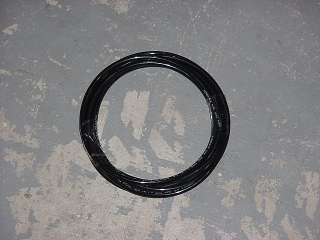
| 44. Run the supplied air brake line from the fitting on the SwayLOC
arm (rotate fitting to the up position) to the solenoid. Allow
enough slack in the in the line for rotation of the arm. Then
from the solenoid connect into the Onboard Air System with the supplied
fitting and remaining hose. |
|
|
| 45. Connect a supplied air connection to the SwayLOC solenoid. |
 |
| 46. Testing of the SwayLOC is simple. If you have the switched version,
ensure you have adequate air pressure, and turn the switch on.
The SwayLOC may disengage immediately, if not, drive a little, the
SwayLOC will disengage when the pressure releases off of the locking
mechanism. Recheck to verify that it disengaged. Reengagement
is as simple as turning off the switch and checking to see if it reengaged.
It may not lock in initially, but will as soon as the arms line up. |