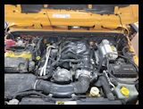
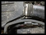
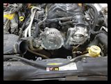
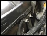
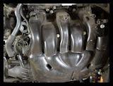
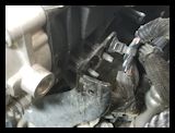
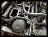
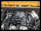
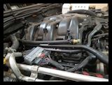
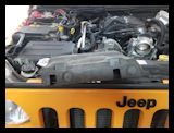
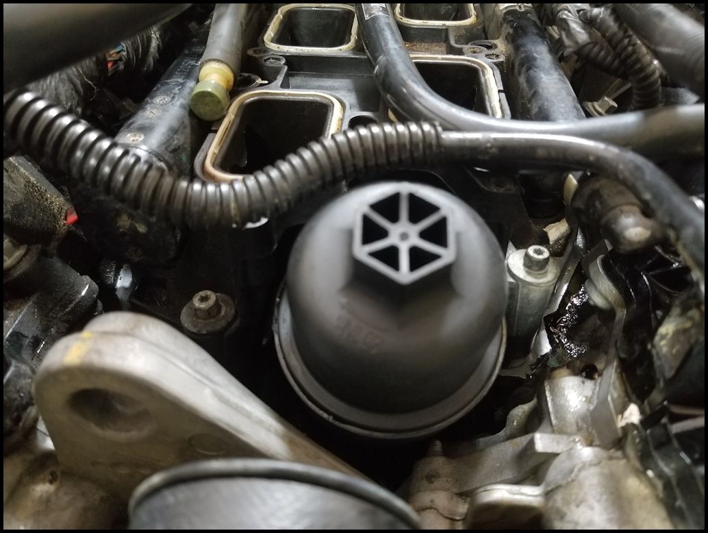
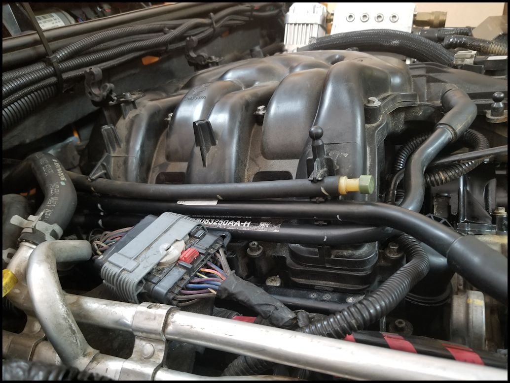
About a year ago I started smelling anti-freeze after I parked the Jeep in the garage. I didn't see anything at first, but I had a good idea that I was quickly becoming another member of the dreaded Jeep JK 3.6L oil cooler leak. A few months later I started noticeing that the antifreeze was disappearing a little faster and I needed to add some to the coolant bottle. It wasn't much longer before I started noticeing a small puddle on the ground below the transmission. Within the span of a couple months this became a case of adding a 1/2 gallon of antifreeze every week. I would estimate that about a year went buy from the time I noticed the leak to the time I changed it out. I should have changed out the cooler long before I got to this point, but I had so many things going on that I had zero time to do anything to the Jeep. To check to see if your oil cooler is leaking, you can remove the engine cover and use a bright light to shine down along the side of the oil filter housing. This should allow you to see into the valley where the oil cooler is located. It should look dry with the metallic silver of the block shining back. Okay, it will probably be a dirty mess if you actually wheel your Jeep. What you should see is the reflection of liquid being thrown back from your light. The valley is pretty big, so you could have a slow leak for a long time with the liquid being burnt off by the hot engine block before you actually see any drippind down along eh bell housing of the transmission.
Note: None of the bolts required much force to loosen them. I'm not 100% certain on the torque settings that I was able to find for this job, but every one was less than 9 ft/lbs of torque. This isn't a lot of torque and we are dealing with lots of plastic parts.
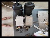
| Parts: |
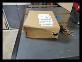
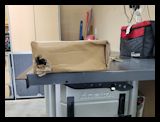
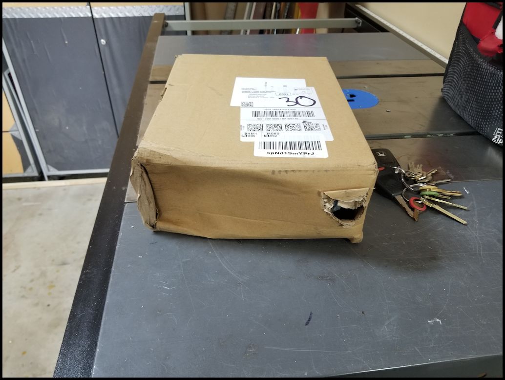
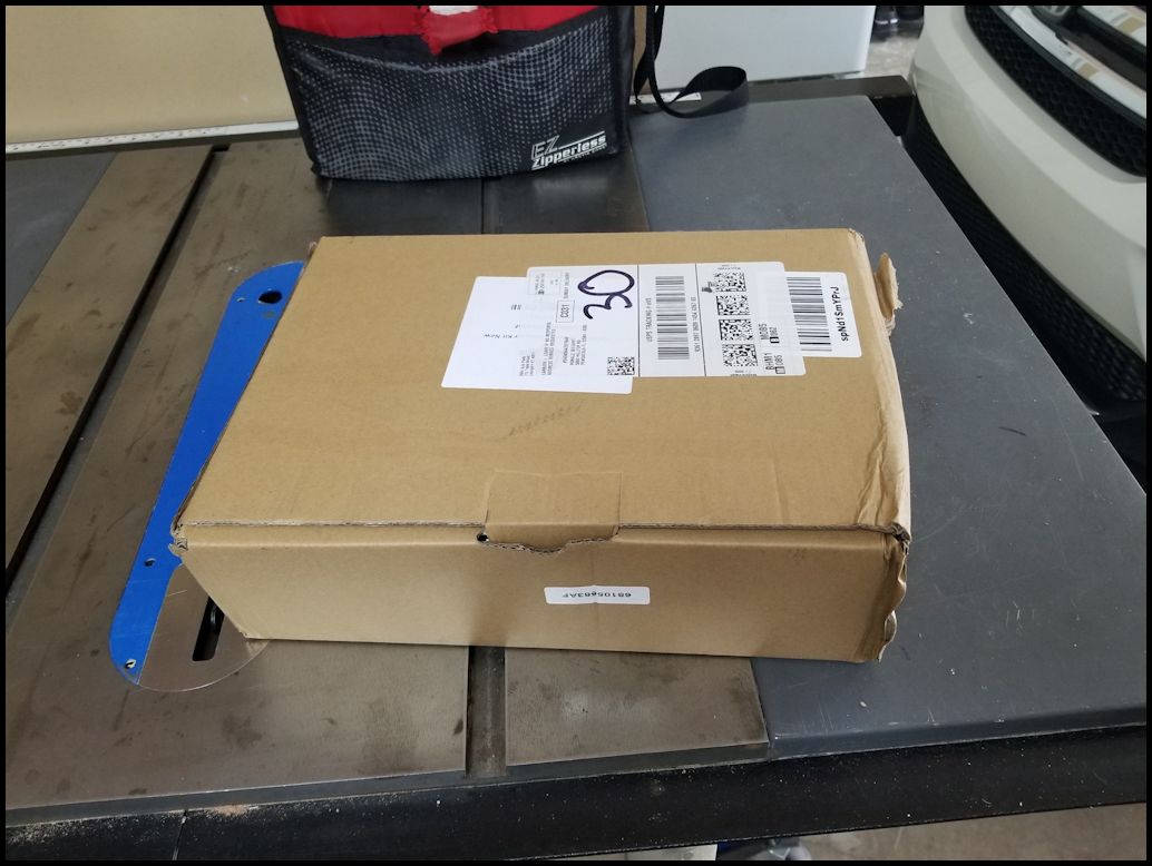
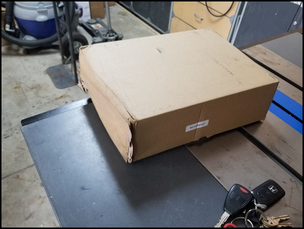
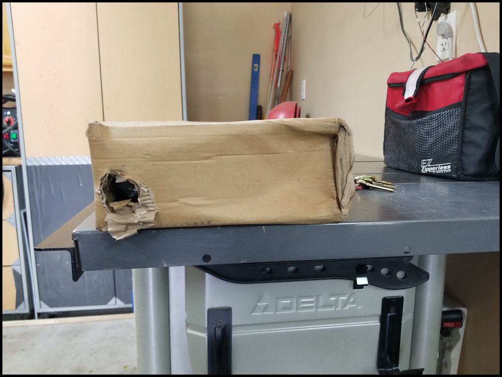
| UPS shipping at it's finest again. Box crushed, with a big hole. The cooler and all the parts were inside the box, but it could have been packaged better. |
 |
 |
 |
 |
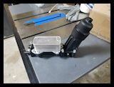
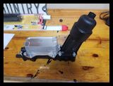
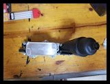
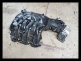
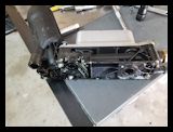
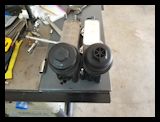
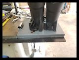
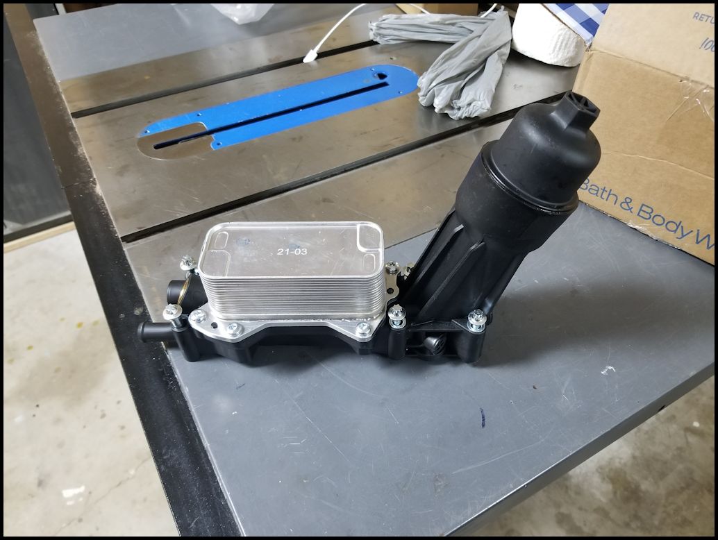
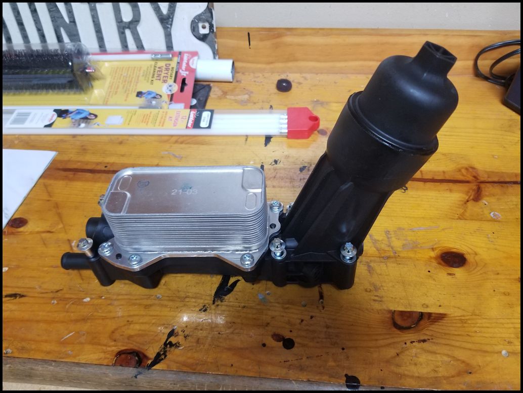
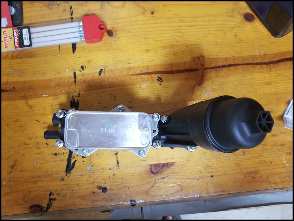
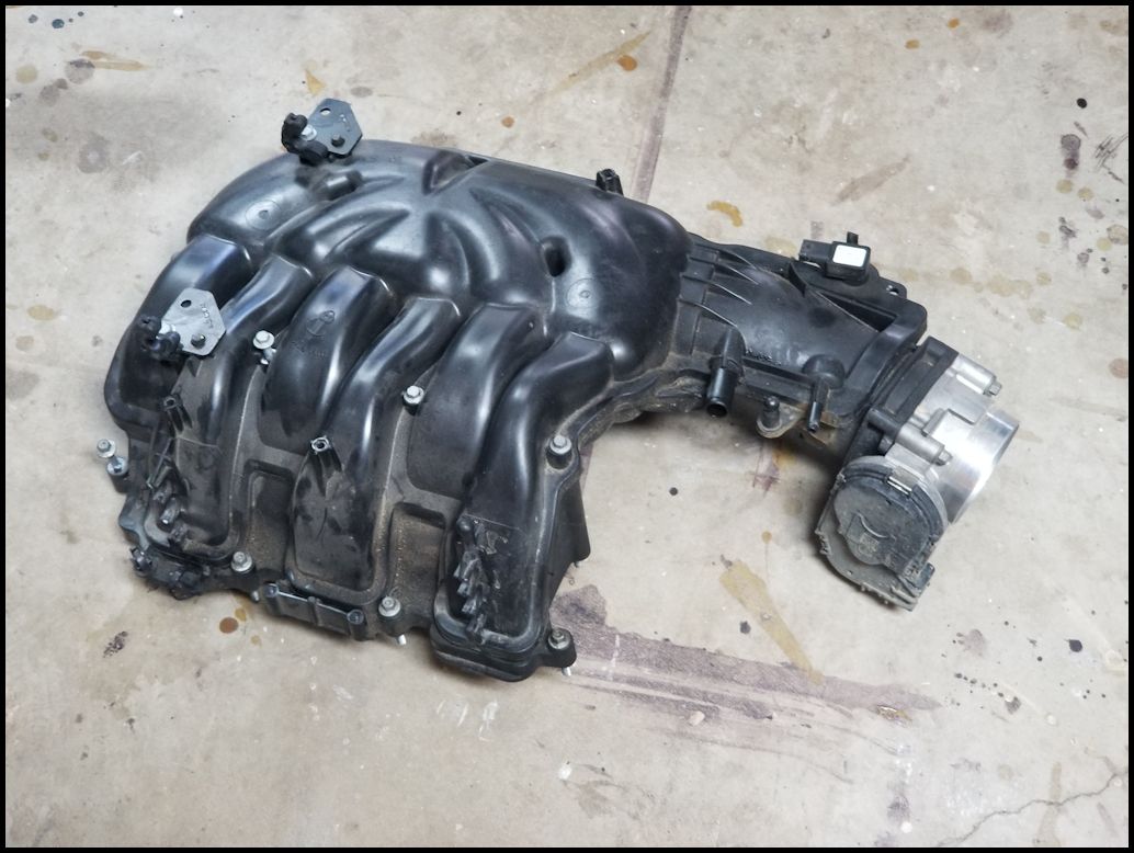
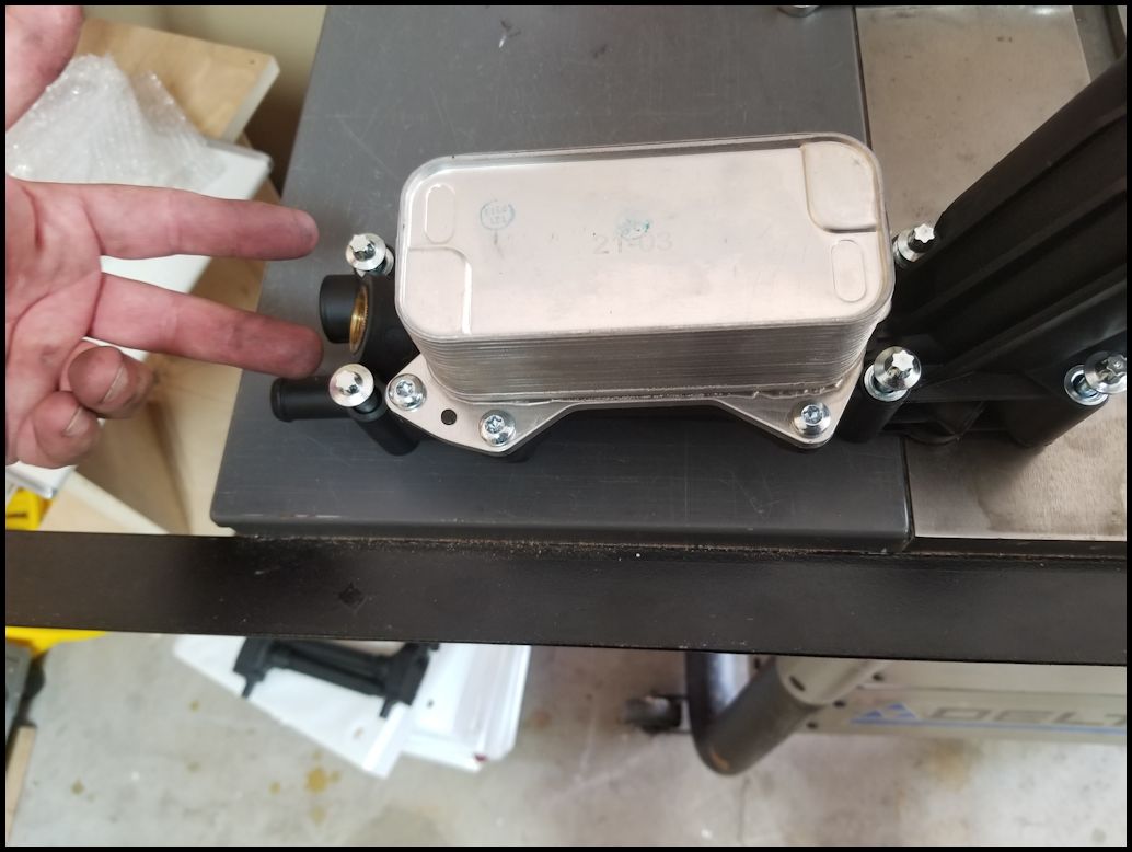
| This is the 2014 oil cooler, but the installation is the same for the 2012 and 2013. I decided to upgrade to the better cooler and filter assembly. |
 |
 |
 |
 |
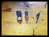
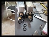
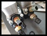
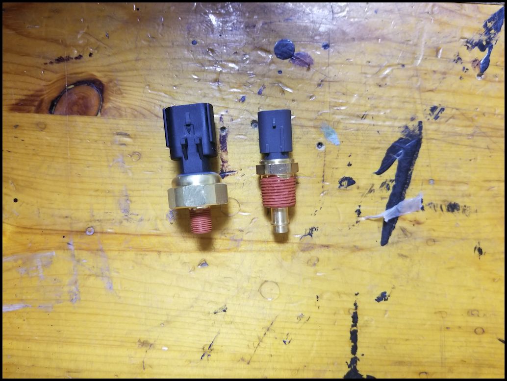
| The sensors do not come preinstalled, but they do come with thread sealant on the sensor. |
 |
 |
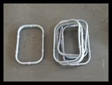
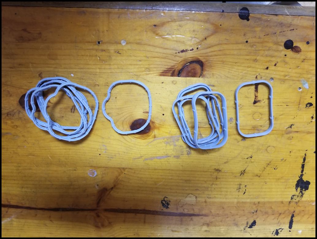
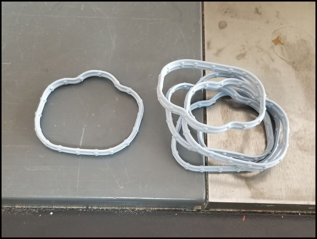
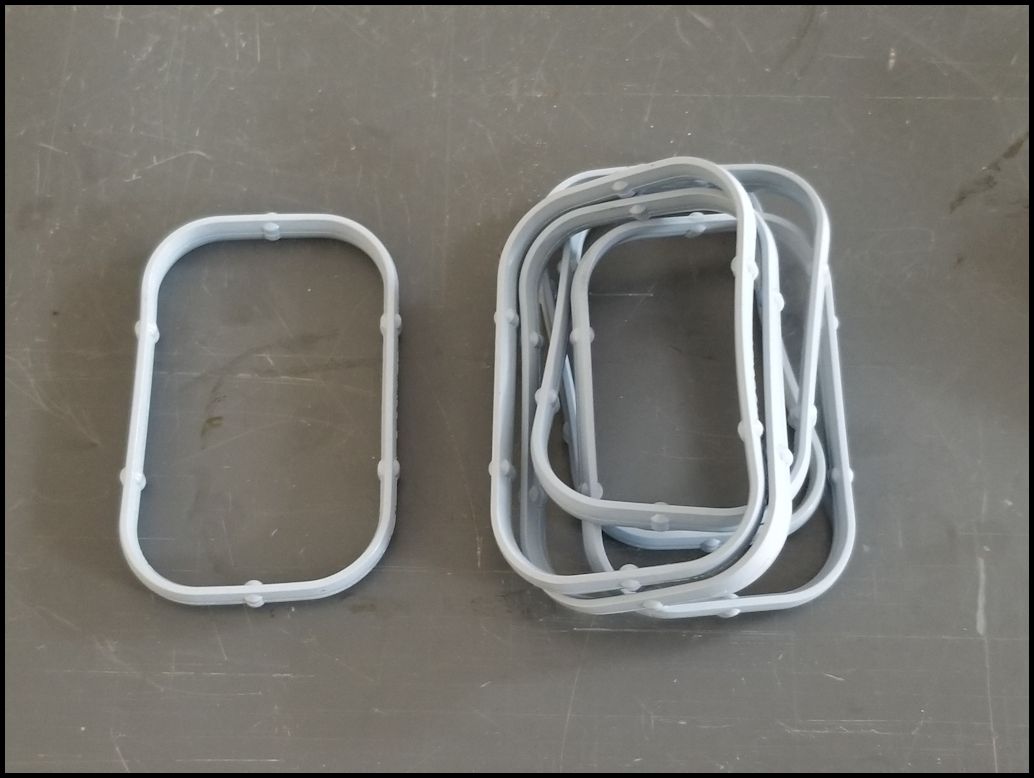
| New upper and lower intake gaskets. |
 |
| |
| Installation: (I will try to break it down into sections) |
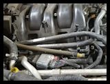
| Upper Intake : |
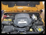
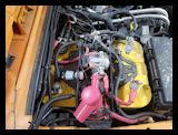
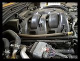
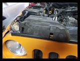
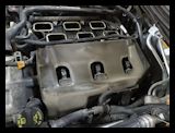
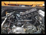
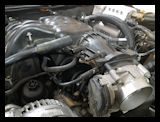
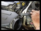
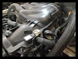
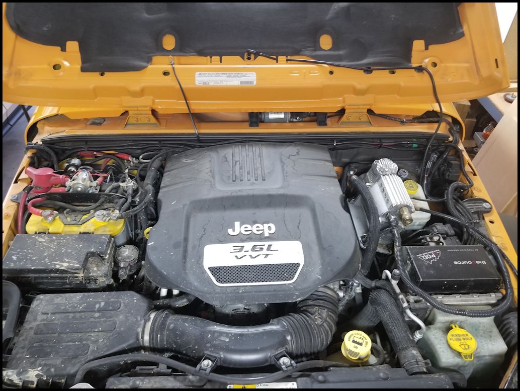
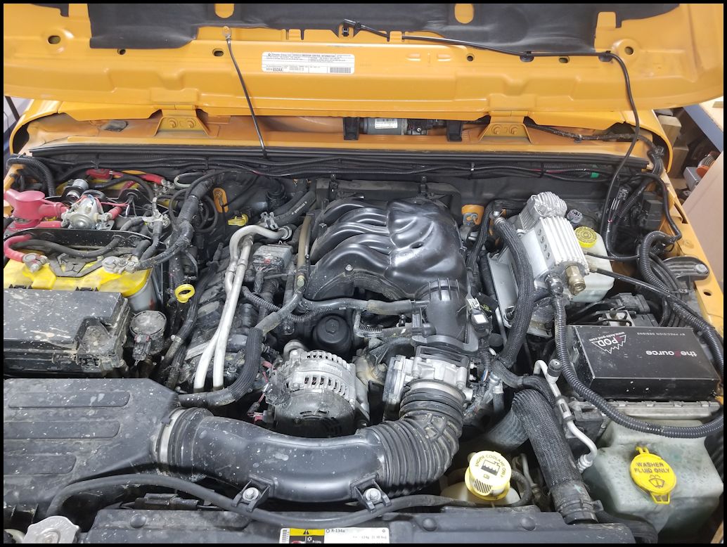
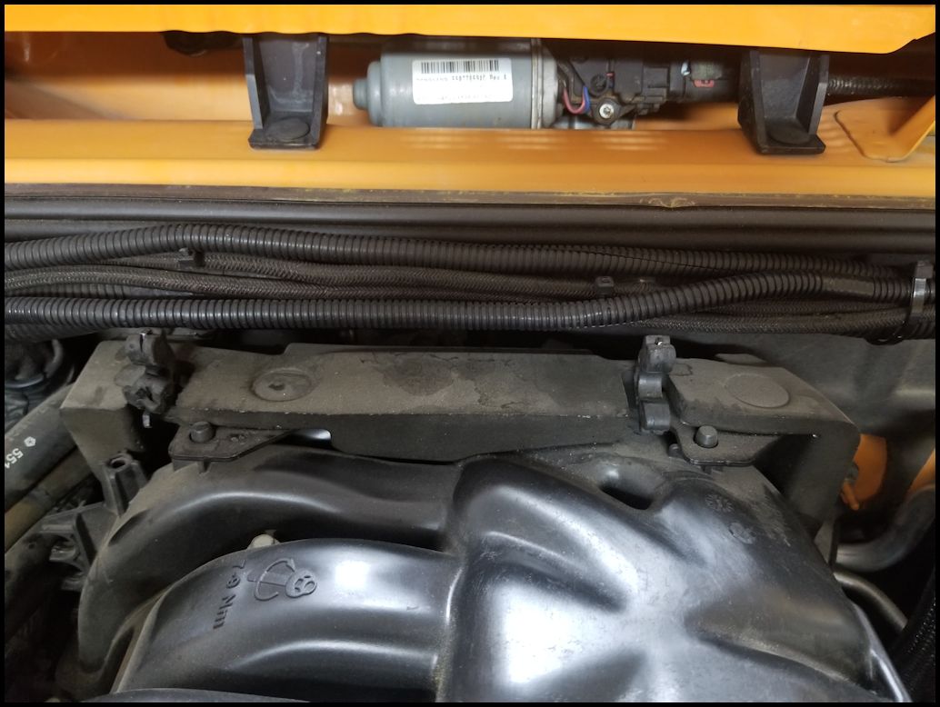
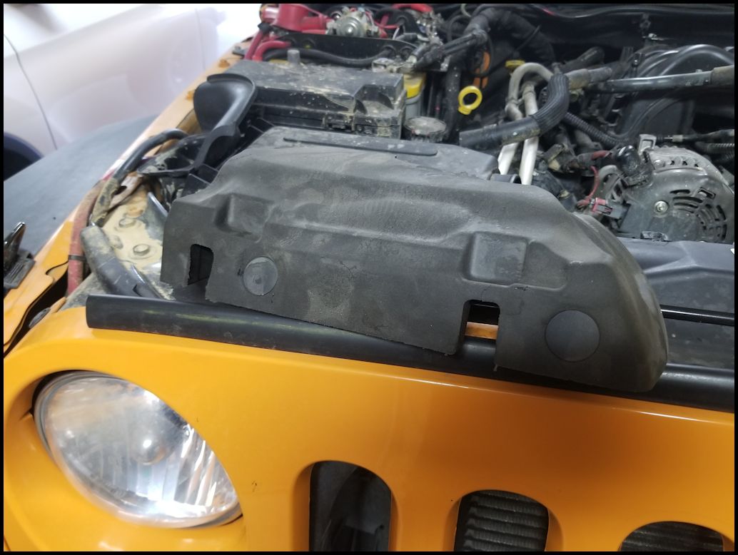
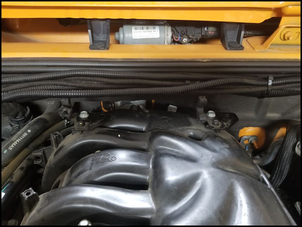
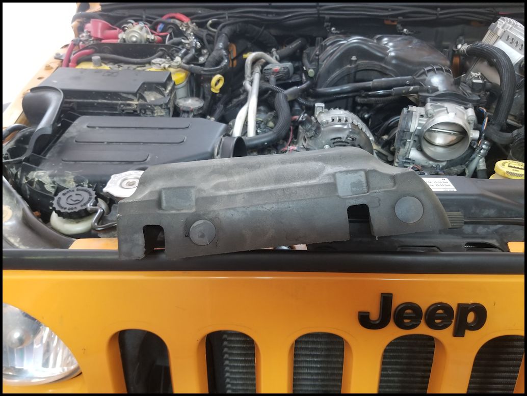
| 1. Remove the engine cover. It lifts up in the front and then pulls forward. You should try to clean as much dirt and debris off of the intake area as possible as you go along. You do not want to get anything down into the intake. |
 |
 |
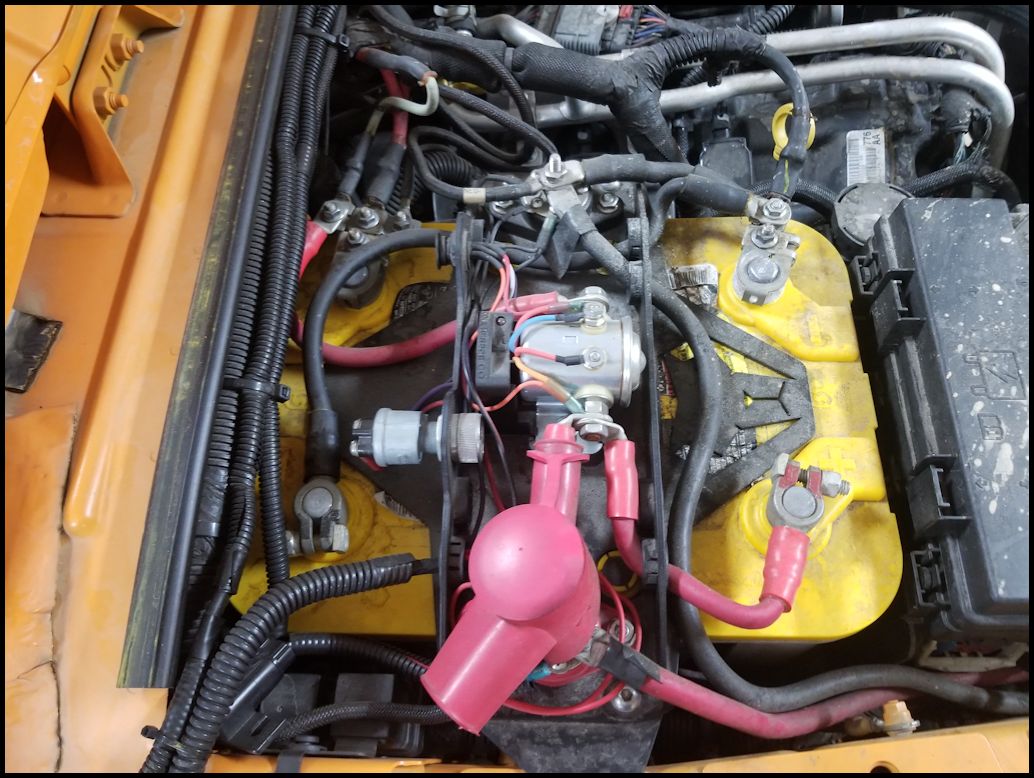
| 2. Disconnect the battery cables. You will need a 10mm or 12mm socket. I have a dual battery setup, so I needed to disconnect a few leads. This is a good time to clean the battery terminals. |
 |
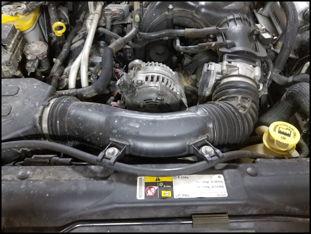
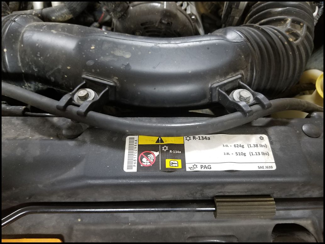
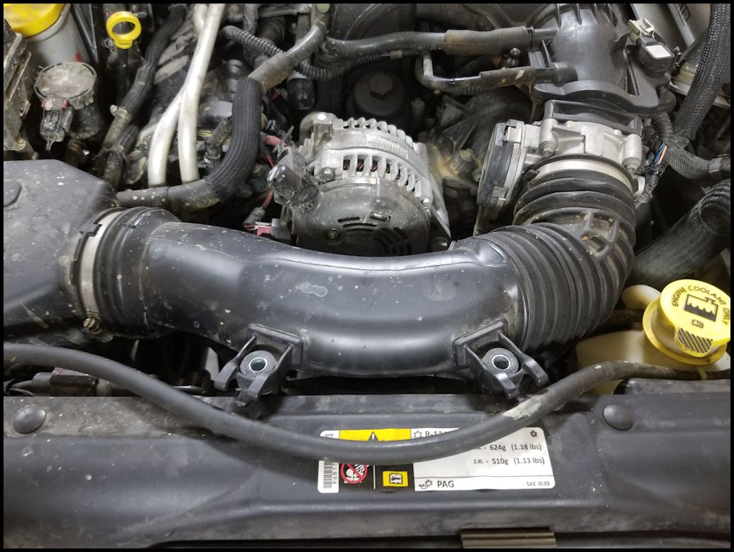
| 3. Remove the two bolts holding the intake to the radiator. You will need a 10mm socket. Pull the radiator overflow hose out of the bracket. |
 |
 |
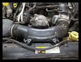 |
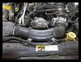
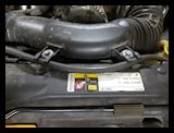
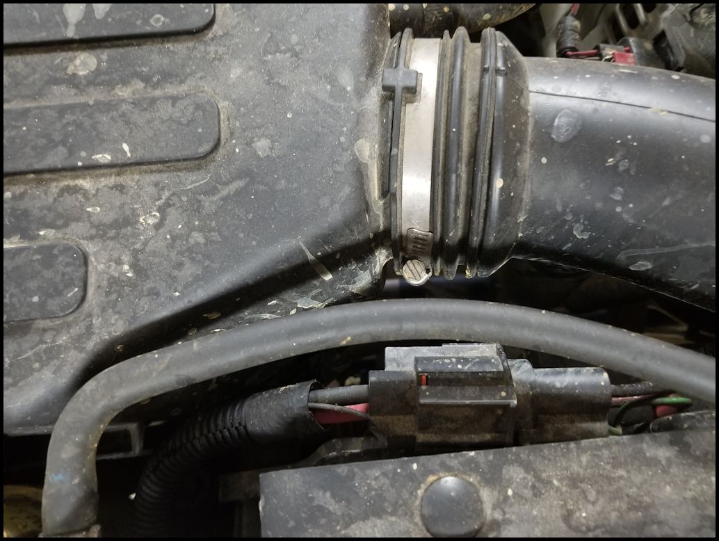
| 4. Loosen the intake hose clamps on both ends of the intake tube. You will need a flat tip screwdriver or a 8mm socket. |
 |
 |
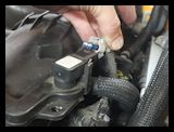
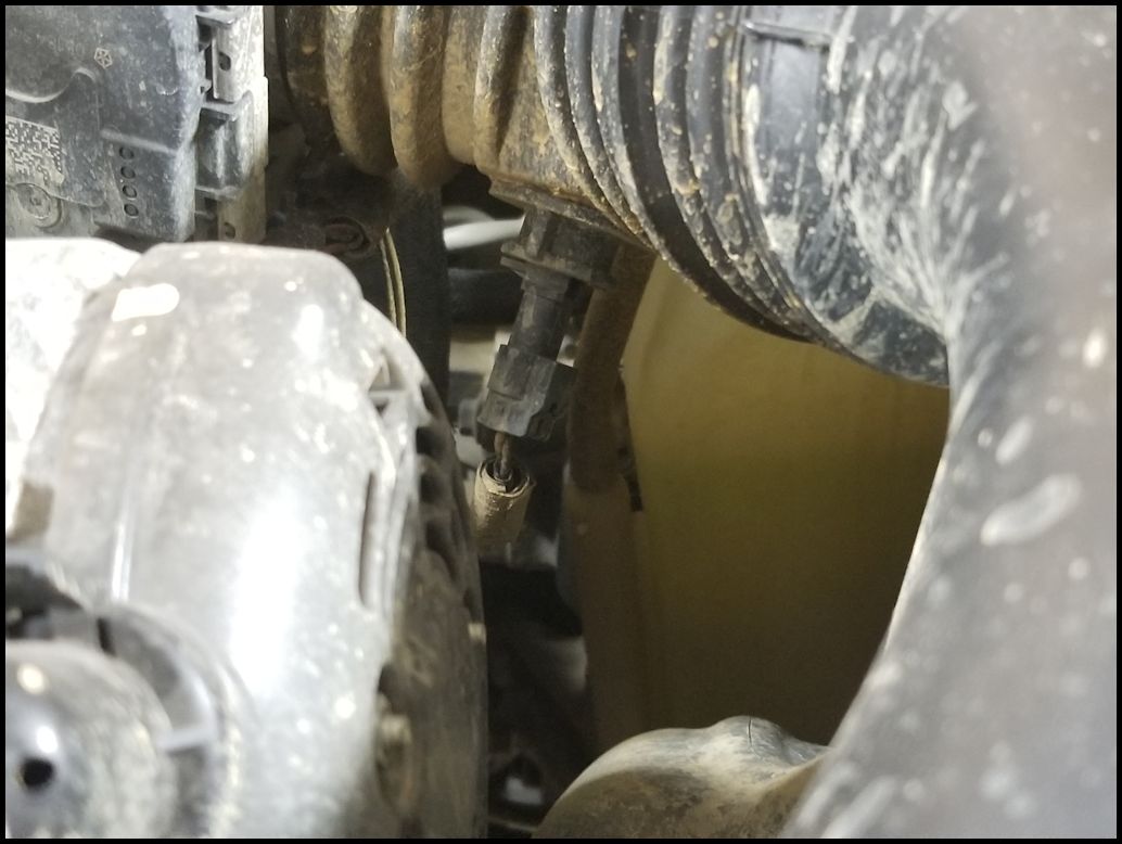
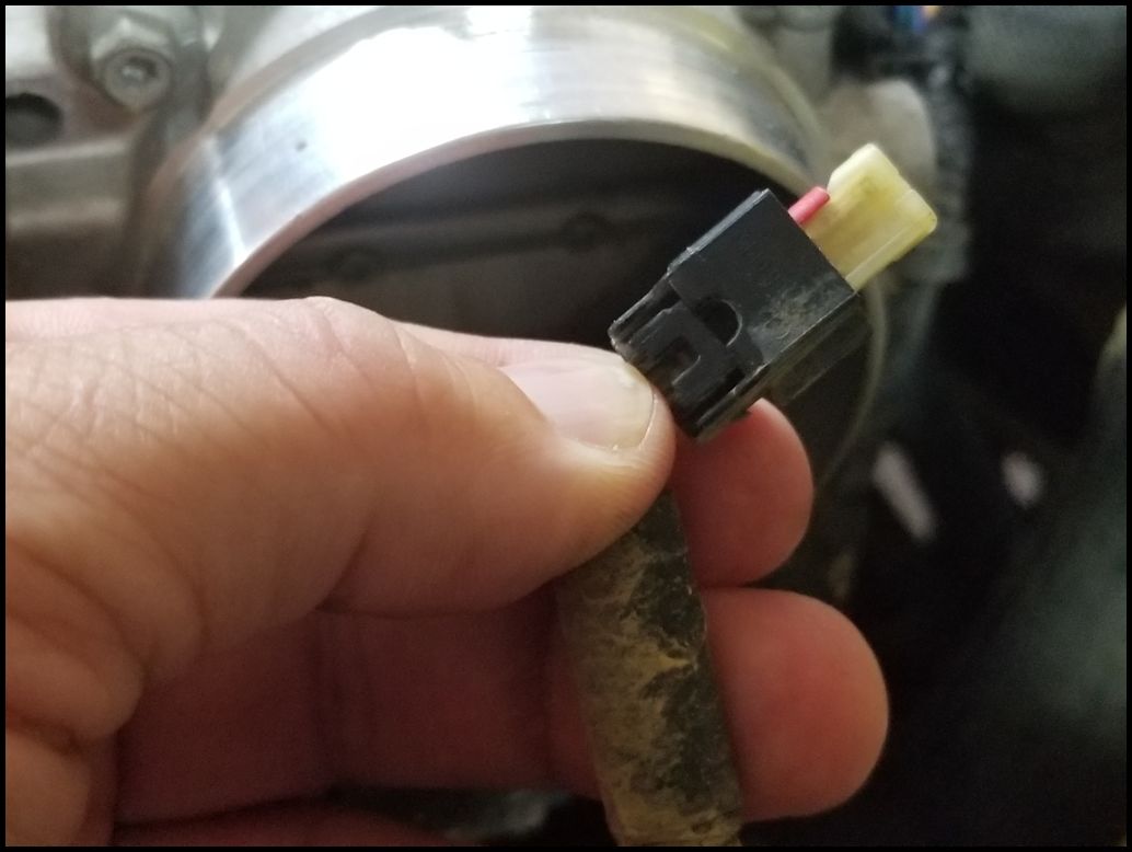
| 5. Remove the IAT sensor connector located underneath the air intake tube. Press on the release and disconnect it from the sensor in the tube. Yours may have a red locking tap that will need to be pulled down first before you can press the release. My 2012 did not have this, but the first time I disconnected it, it was extremely difficult to get free. You may need to do the next step to get better access to it. |
 |
 |
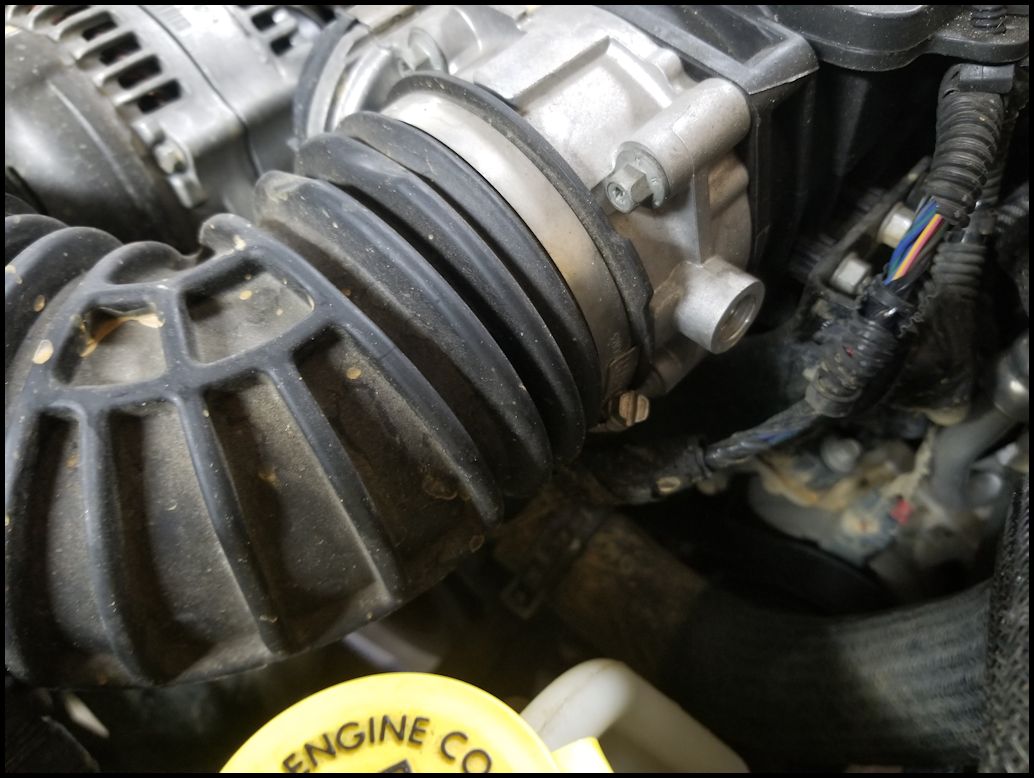
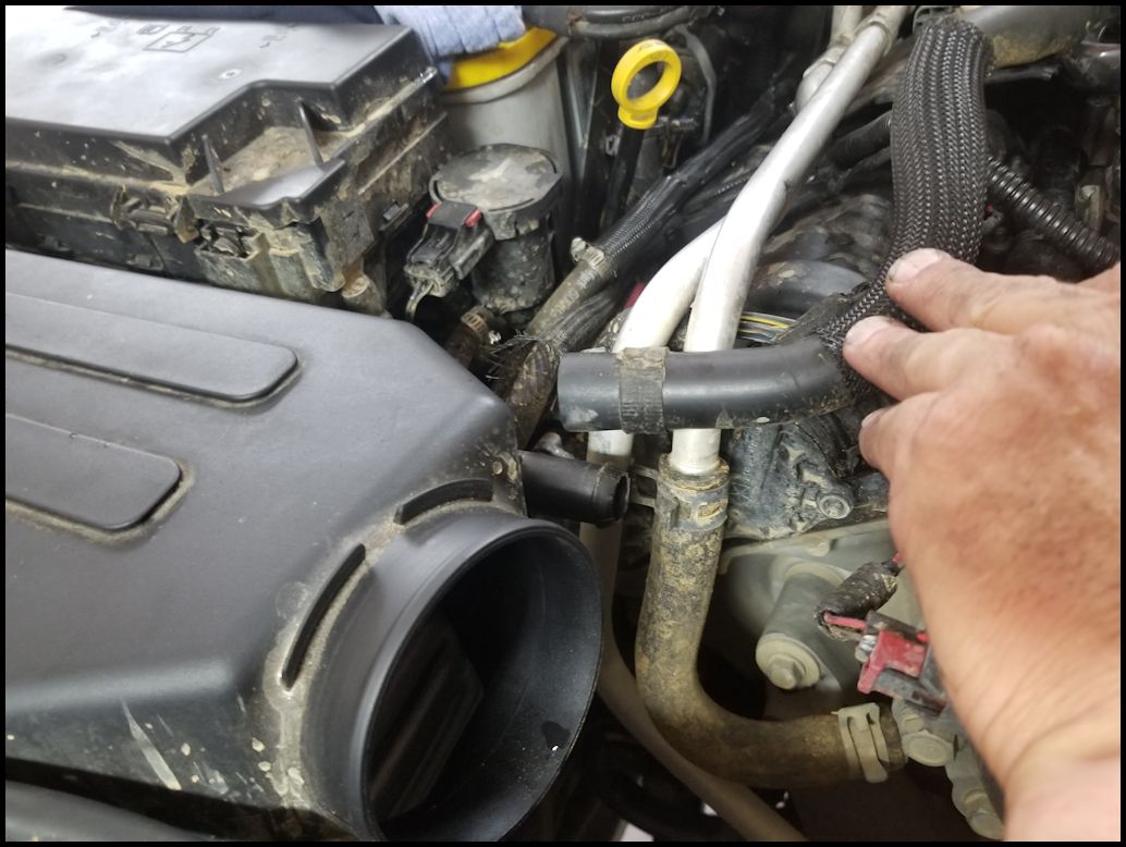
| 6. Remove the air intake tube from the filter box and throttle body. If you haven't completed step 5 be careful how far you lift the tube before you disconnect the IAT sensor cable. If you are going to be working on this over the period of a few days I recommend covering the throttle body opening. I used a ziplock bag and a rubber band or blue painters tape in the past. |
 |
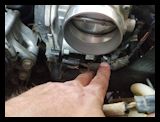
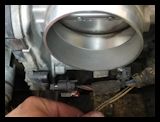
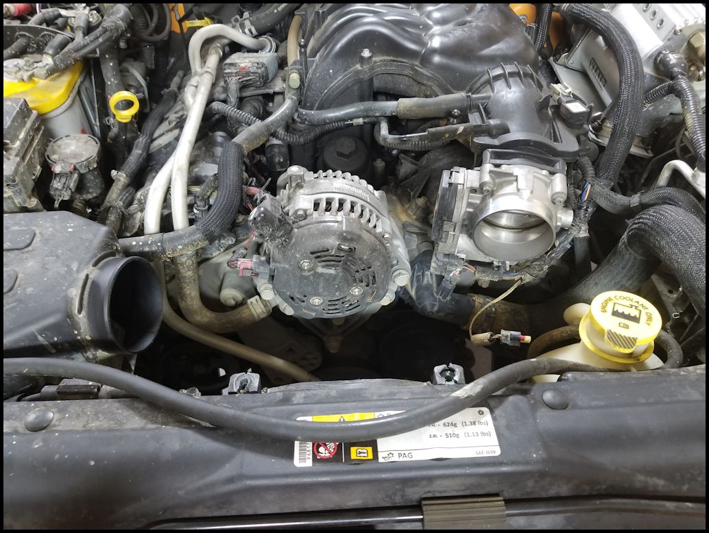
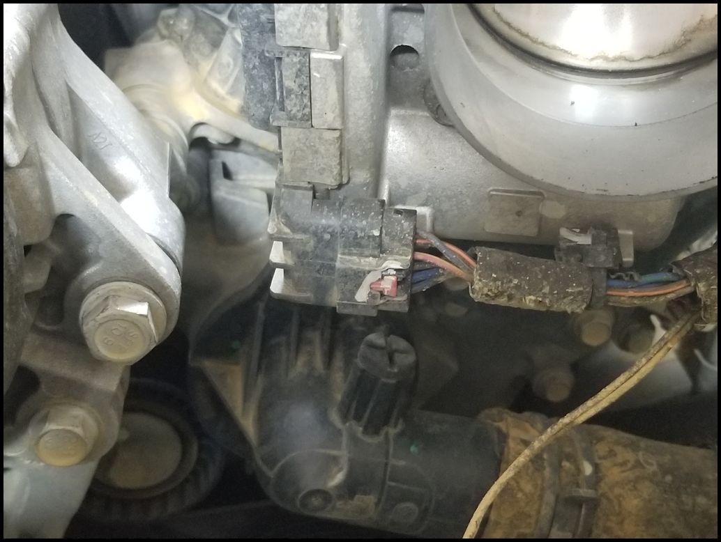
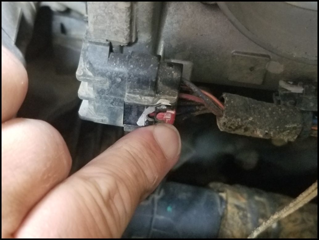
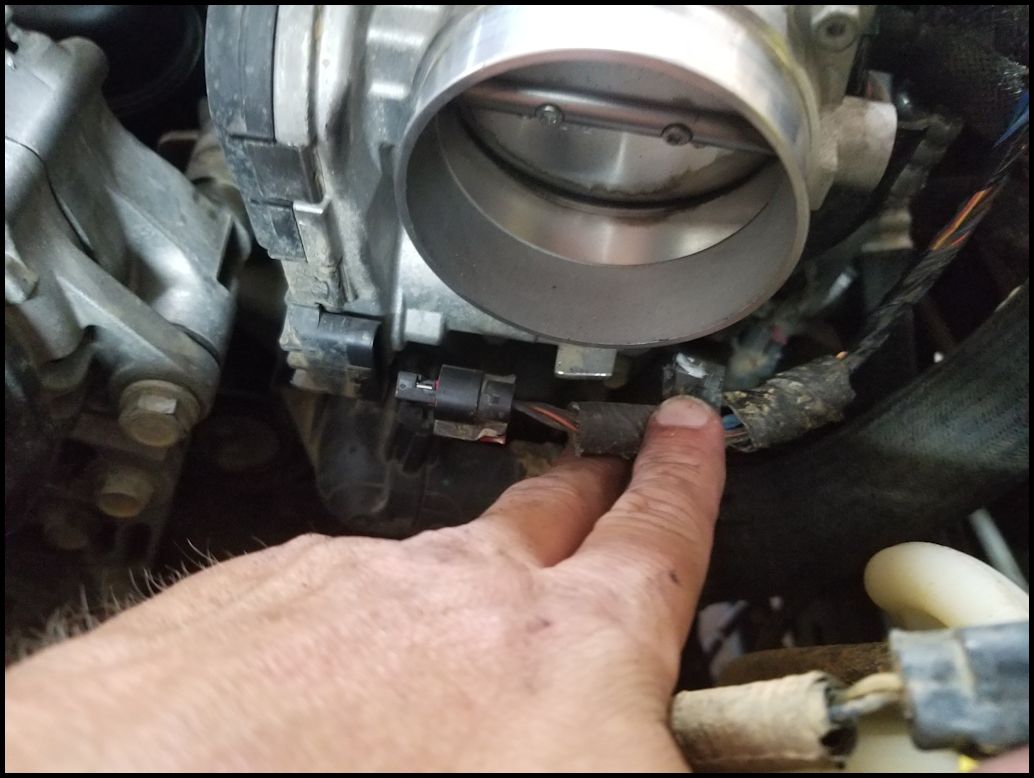
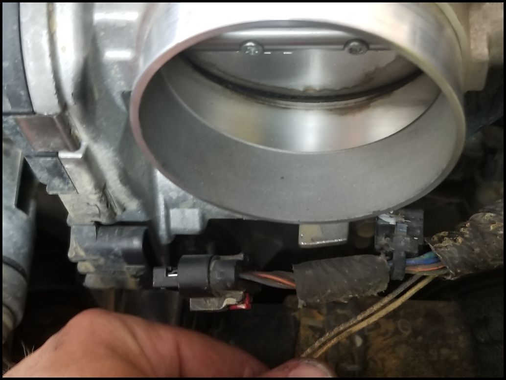
| 7. Disconnect the throttle body connector located at the bottom front of the throttle body. There is a little red locking tab that needs to be pulled back before it will release the connector. Remove the cable holder from the throttle body. It is a small plastic clamp that holds onto a tab on the throttle body just to the right of the connector. It just pulls off the tab. |
 |
 |
 |
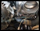
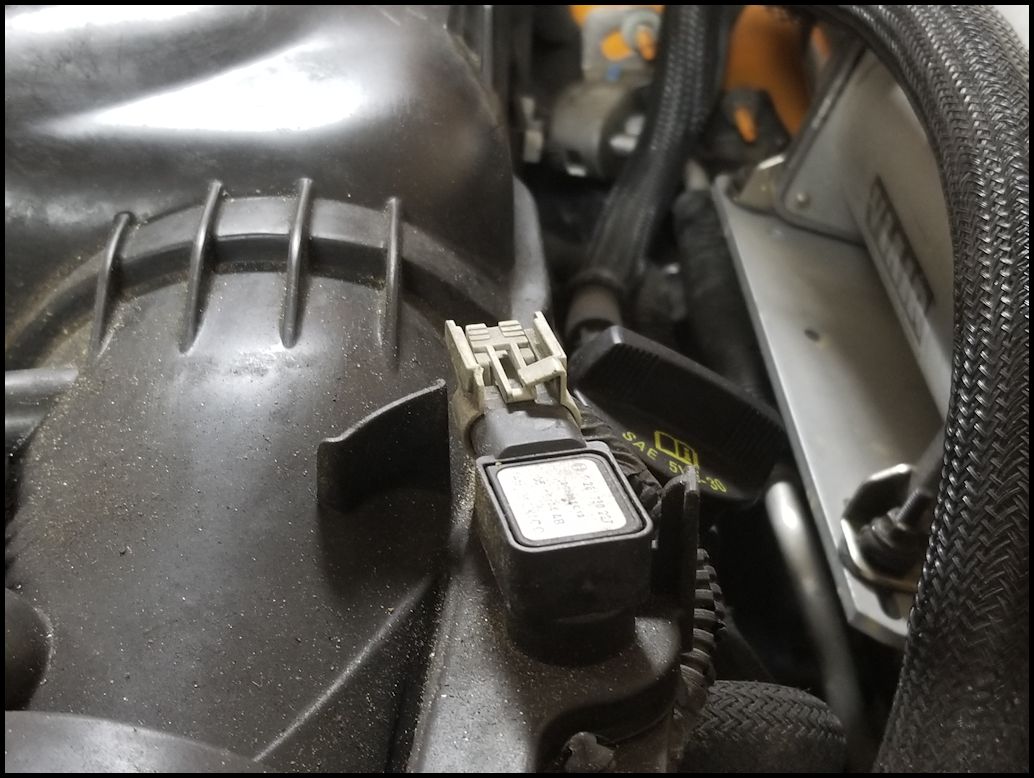
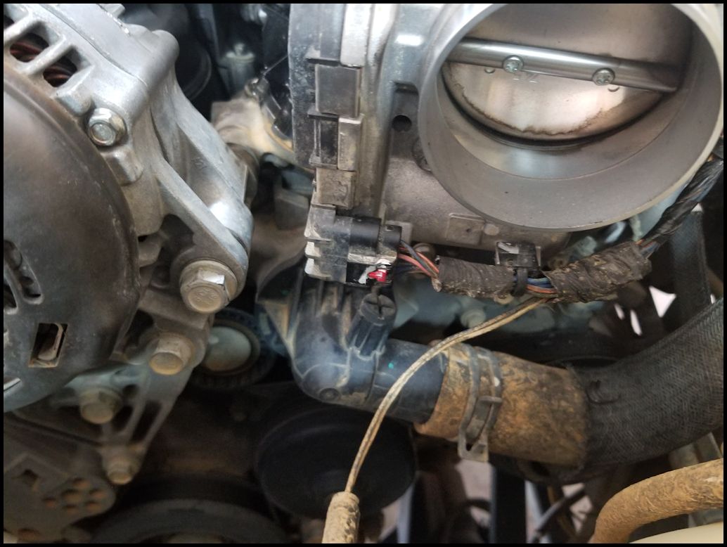
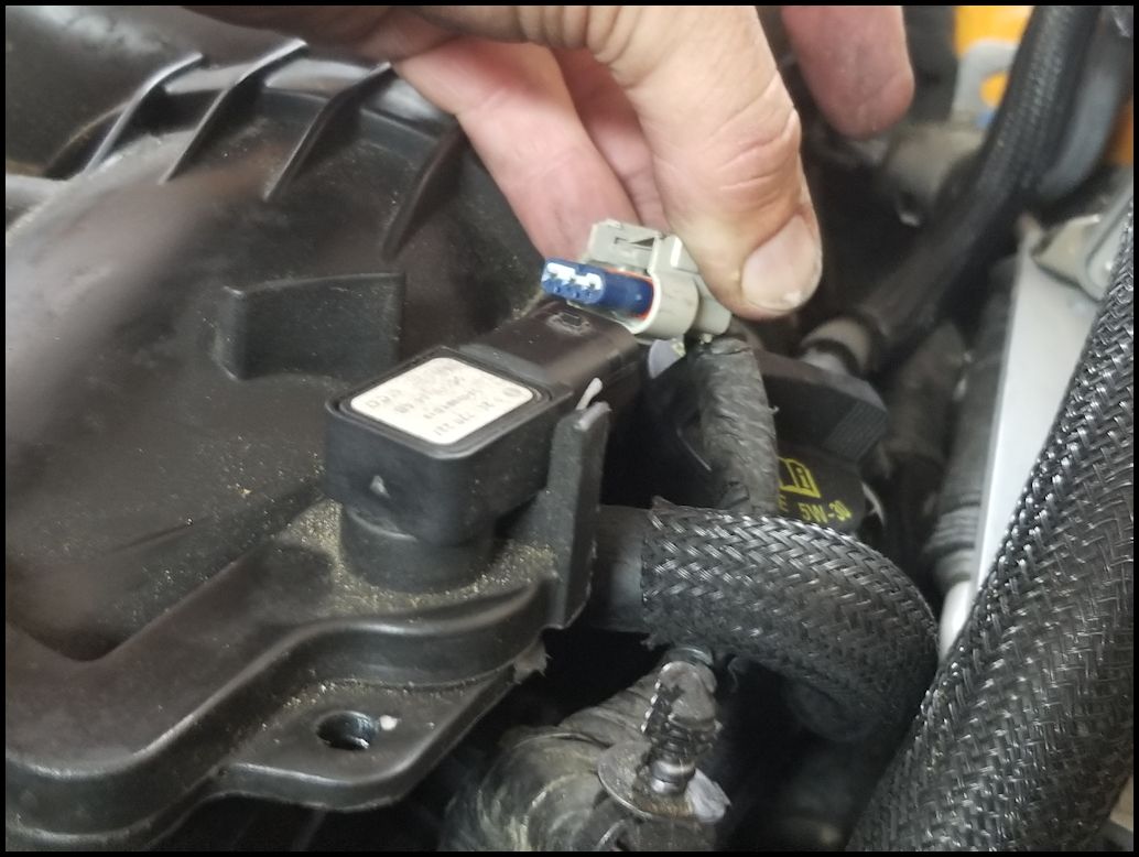
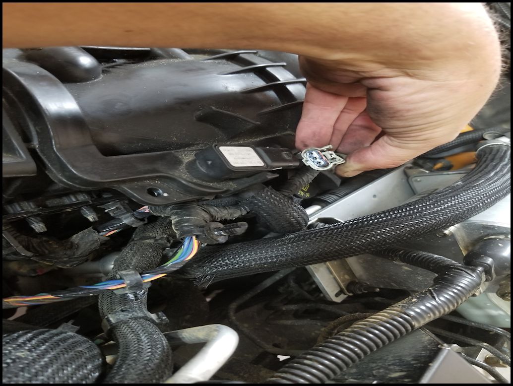
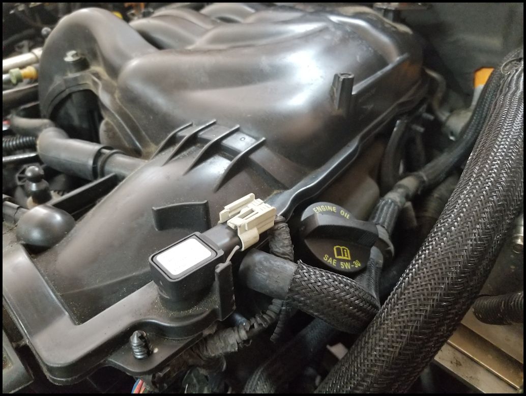
| 8. Disconnect the MAP sensor located on top of the upper intake inlet. |
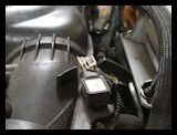 |
| 9. Remove the harness holders from the upper intake inlet. You will need a trip removal tool. |
 |
 |
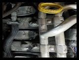
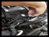
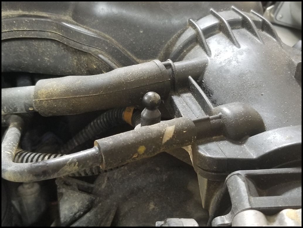
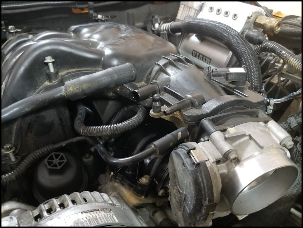
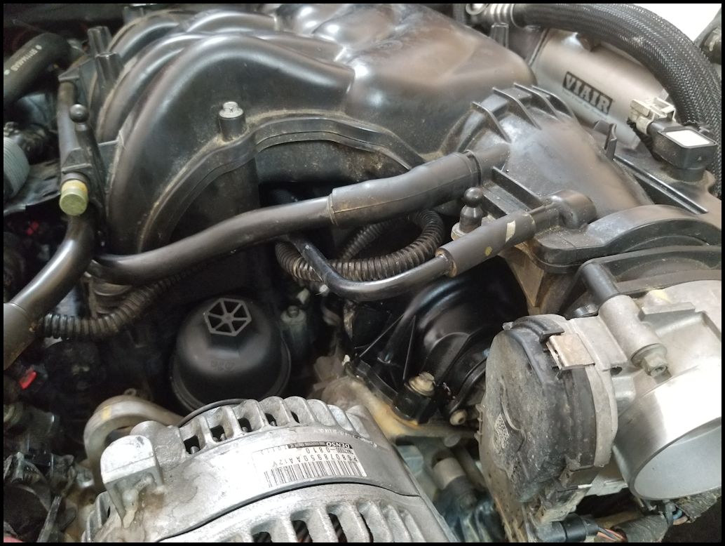
| 10. Remove the two vacuum lines from the left side of the upper intake inlet. You may need to give these a twist back and forth to break the rubber to plastic seal before you can work them off. |
 |
 |
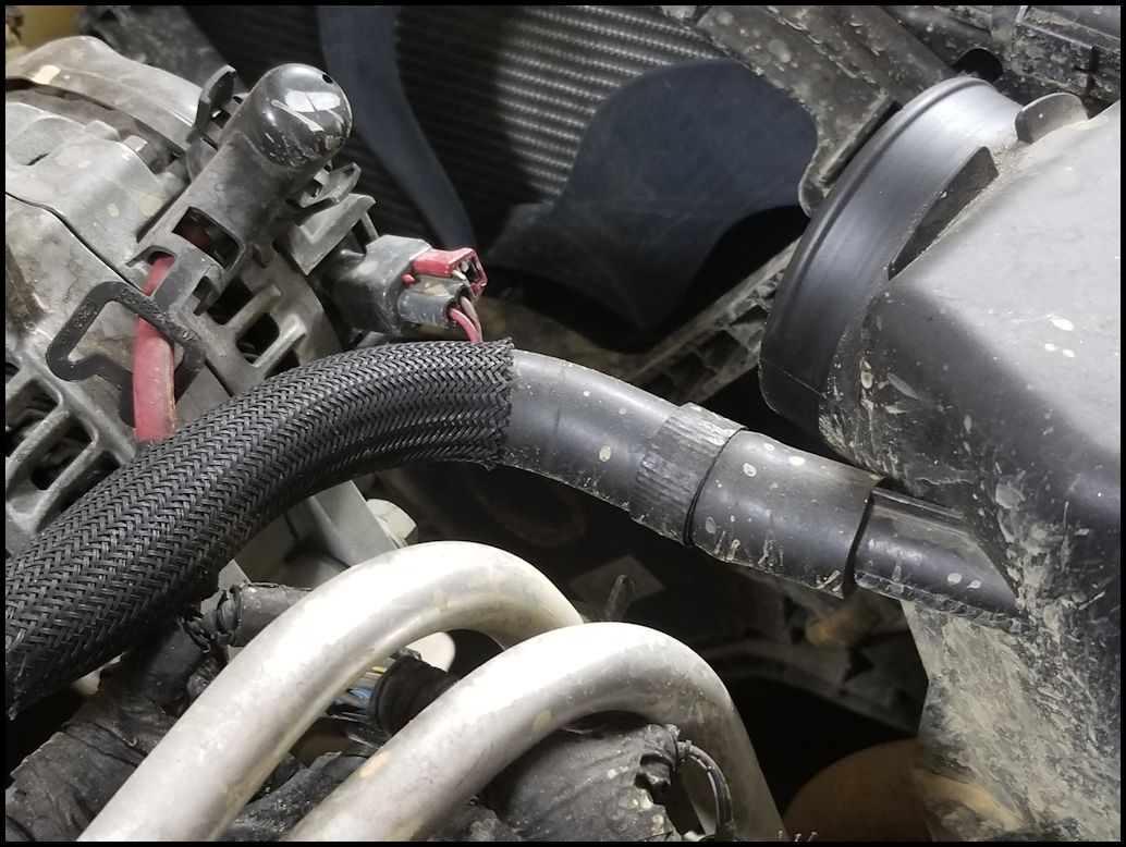
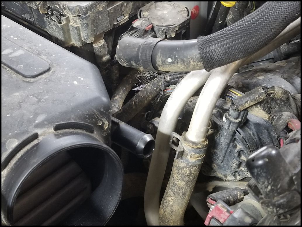
| 11. Remove the crankcase line from the air box. You may need to give this a twist back and forth to break the rubber to plastic seal before you can work it off. |
 |
 |
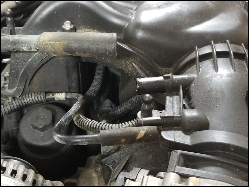
| 12. Remove the transfer case air breather and other vacuum lines from the two holders on the left side of the upper intake. They just pulls out. |
 |
 |
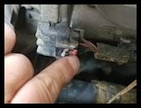
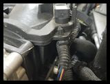
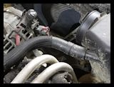
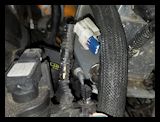
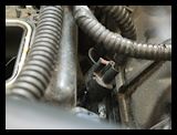
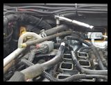
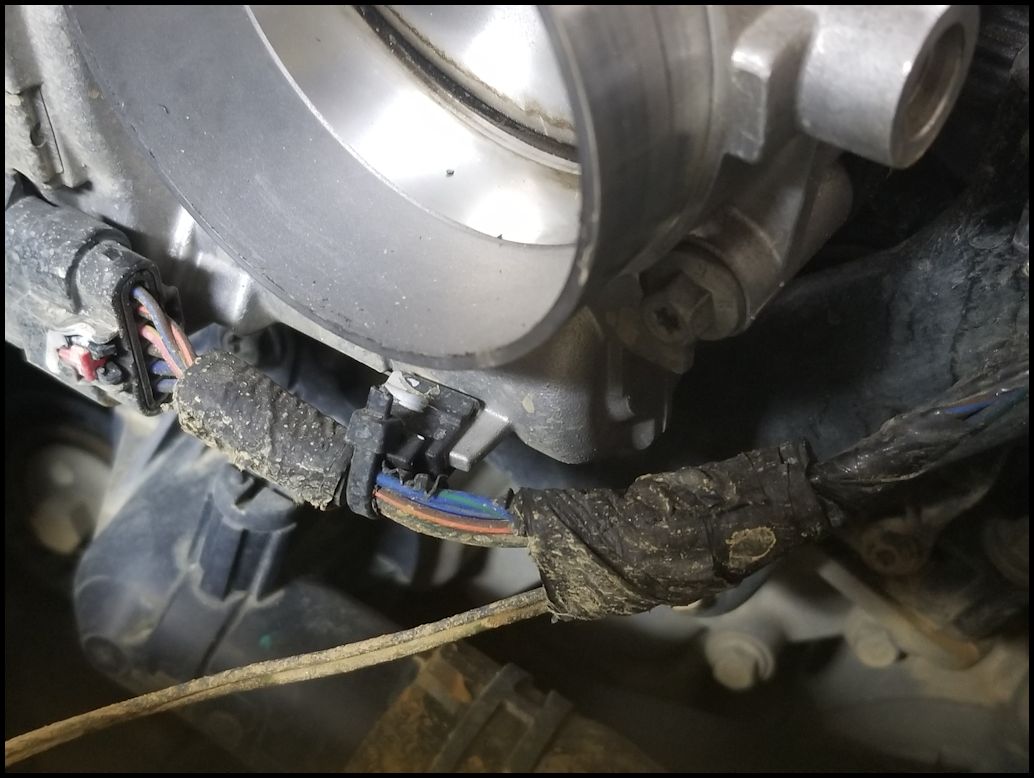
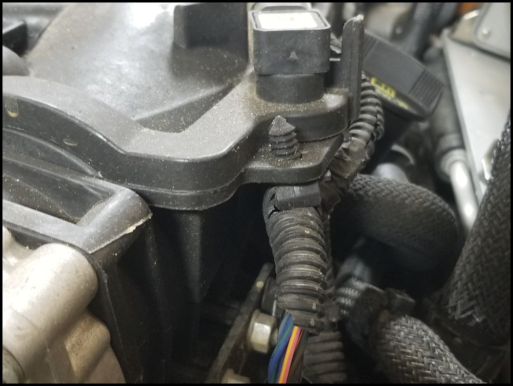
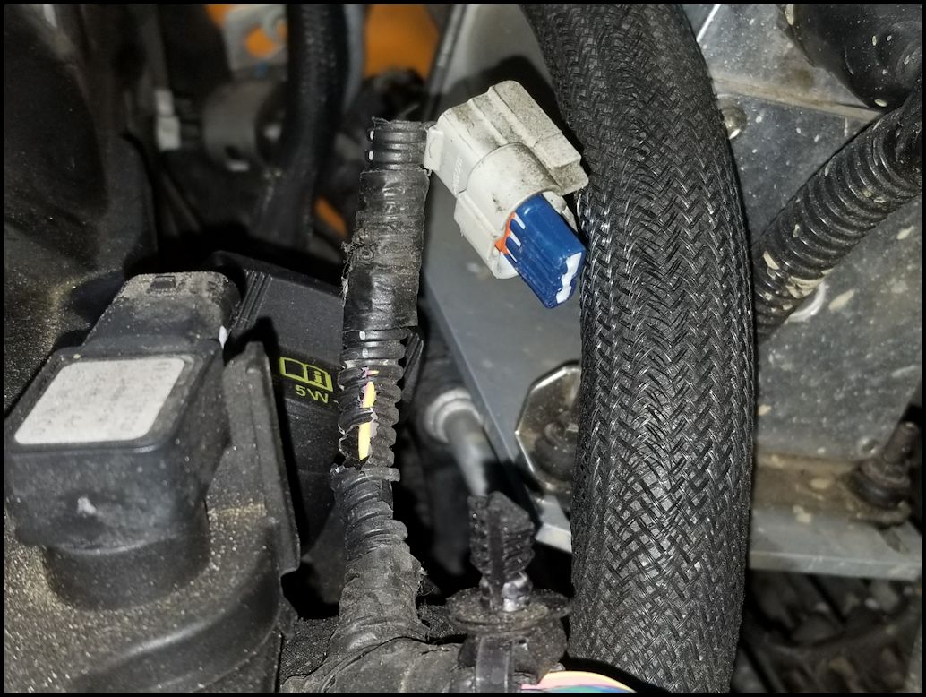
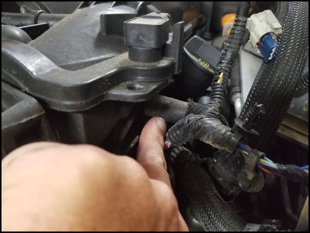
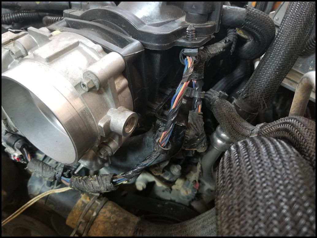
| One thing I was noticeing was that the shroud over the wires had hardened and was cracking away leaving pieces everywhere. This would become a problem later in disassembly, and also become a project that I would need to tackle at a later date. |
 |
| 13. Disconnect the brake booster vacuum line located underneath the MAP sensor. You may need to give this a twist back and forth to break the rubber to plastic seal before you can work it off. |
 |
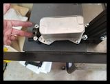
| 14. Remove the four (4) nuts holding the upper intake assembly to the support brackets. You will need a 10mm socket or combo wrench. |
 |
 |
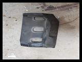
| 15. This step may not actually be needed. The only reason I could see was to make it easier to access one of the upper intake bolts located below the left side of the foam. Remove the sound insulation foam from the back side of the engine. You will need a trim removal tool to remove the two retainers installled in the top of the foam. Then carefully wiggle the foam up and out from behind the intake. |
 |
 |
 |
| 16. Unscrew (the bolts are retained in the upper intake so they don't come all the way out) the seven (7) bolts holding the upper intake to the lower intake. There are three (3) down the center of the intake and four (4) on the left side. The hardest one to get to is the one all the way in the back where the foam was. I pulled up on each bolt to make sure that they were loose. You will need a 8mm socket for the bolts and a long extension for the back one. The four (4) on the side can also be unscrewed with a T20 torx bit. |
 |
 |
 |
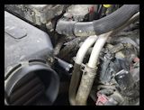
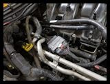
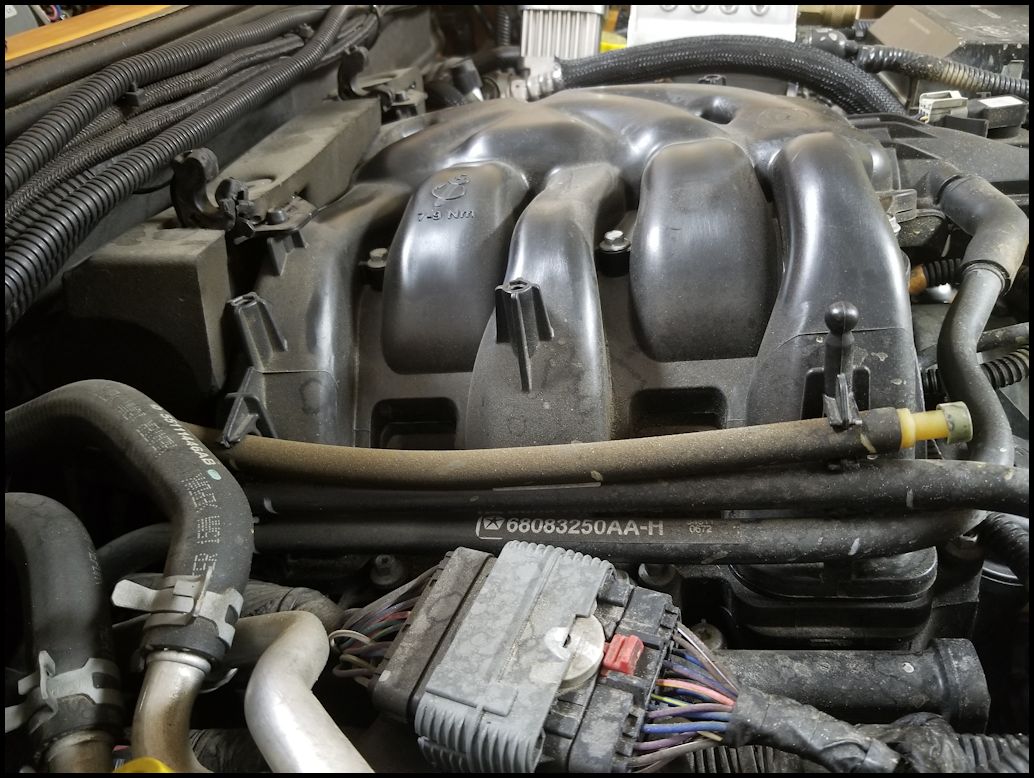
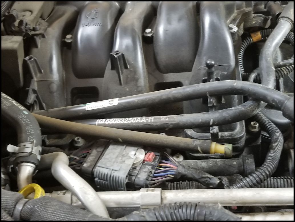
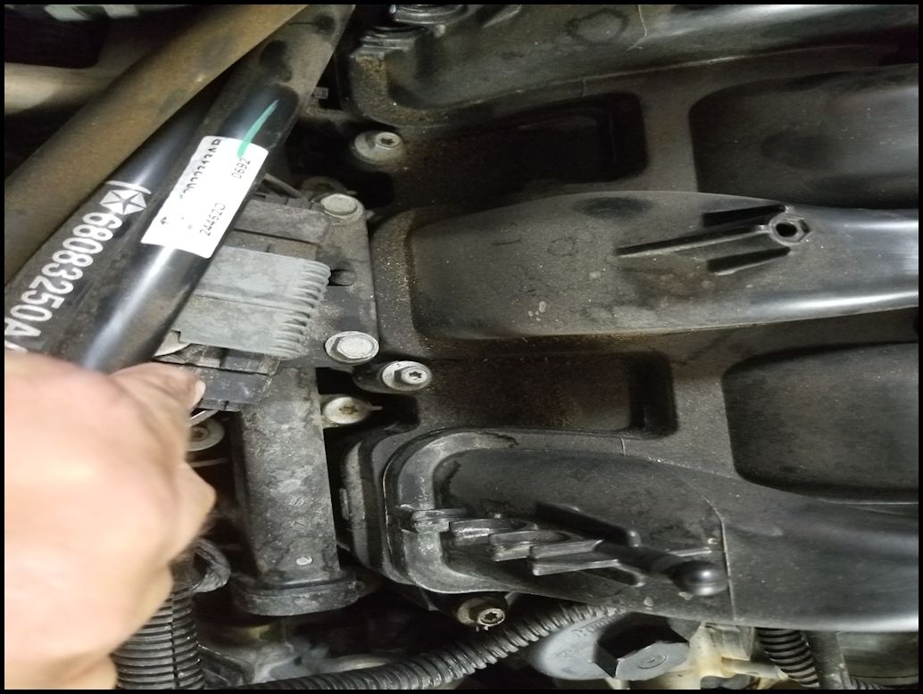
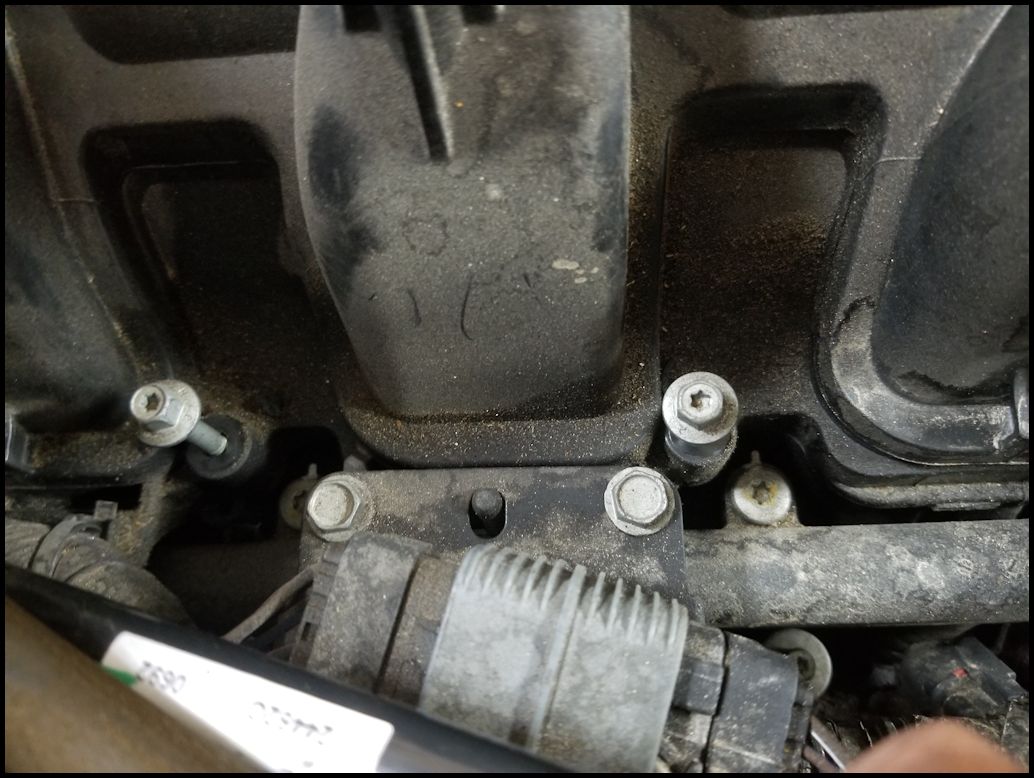
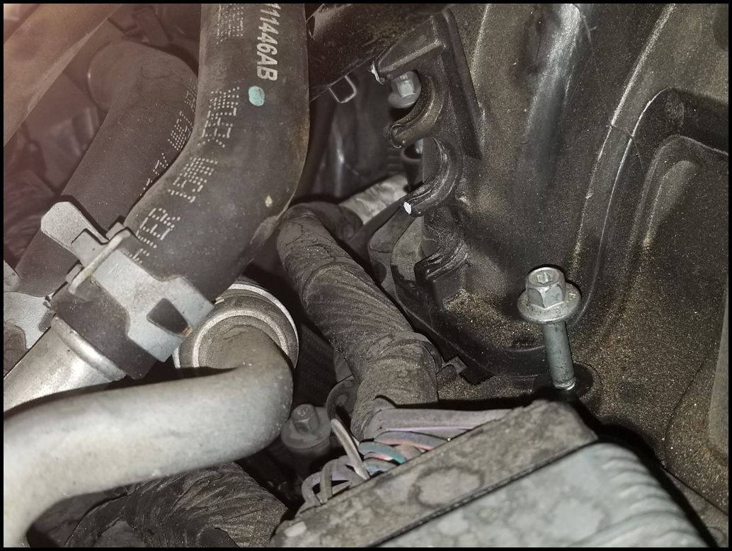
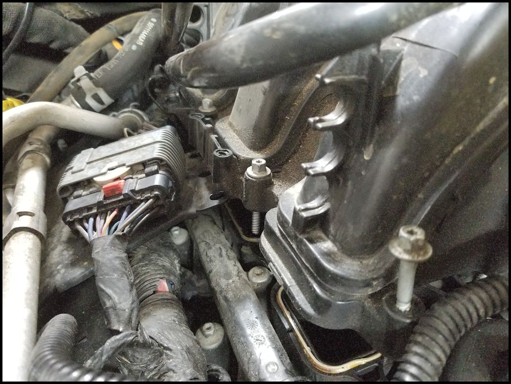
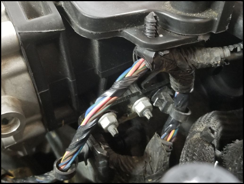
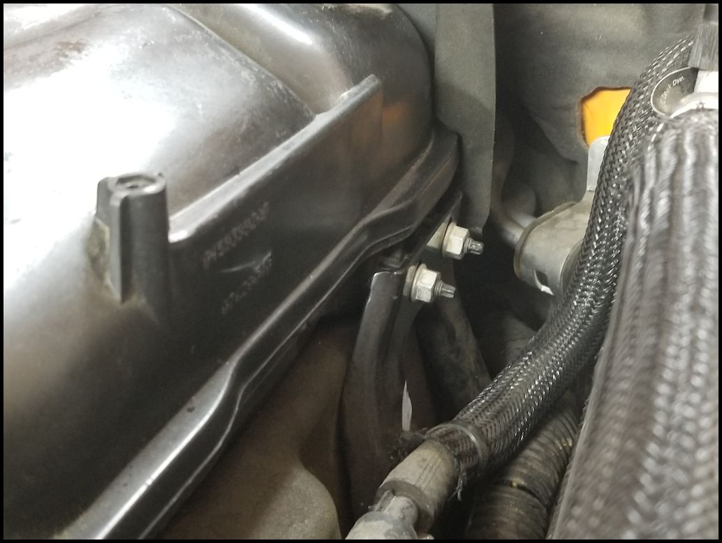
| 17. Remove the two (2) bolts holding the bracket for a large electrical connector and the heater hose hard lines. The bracket is bolted to the intake above the fuel rail on the left side of the intake between two of the intake bolts. You will need a 10mm socket and extension. |
 |
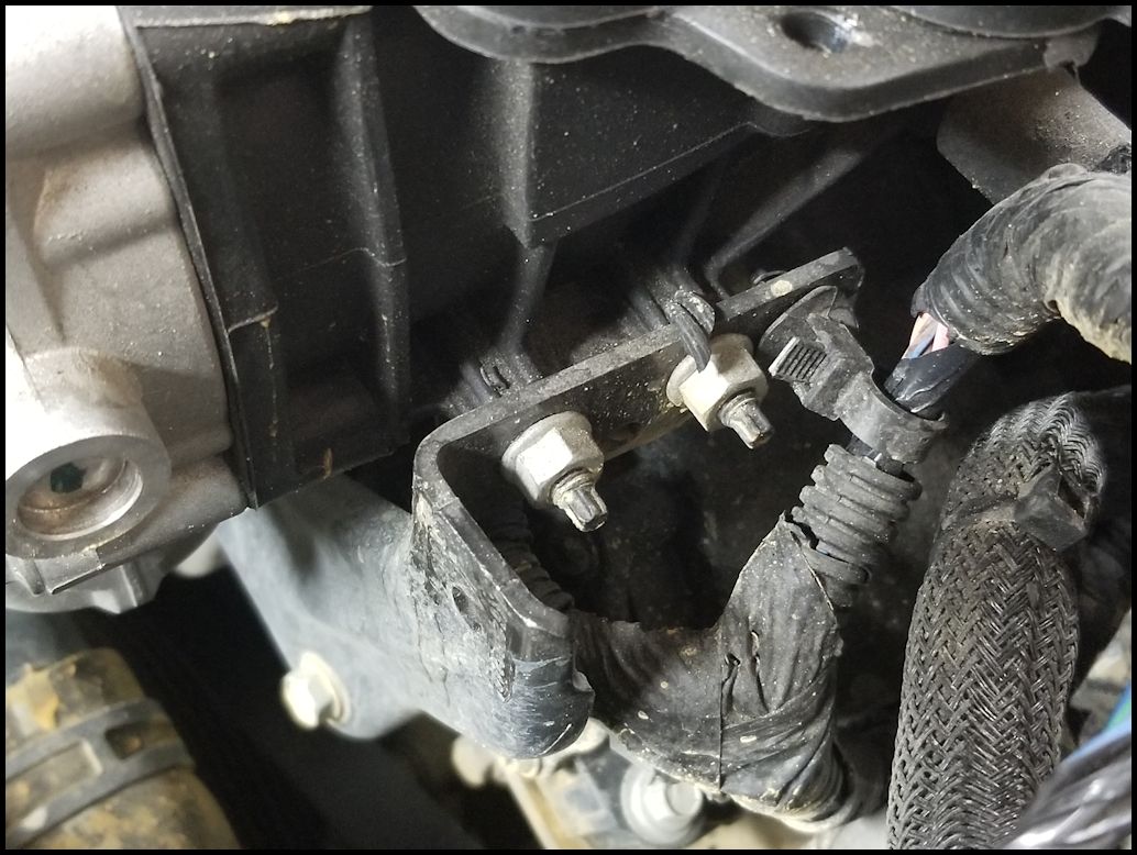
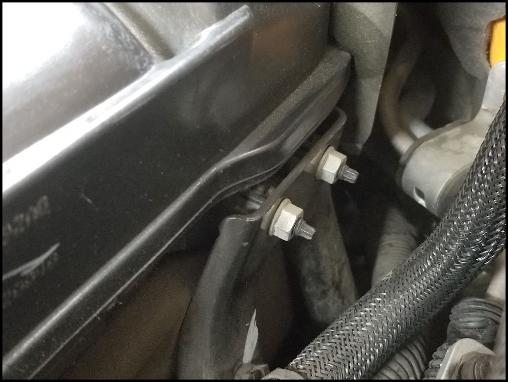
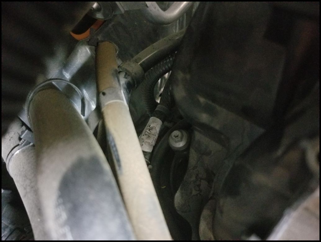
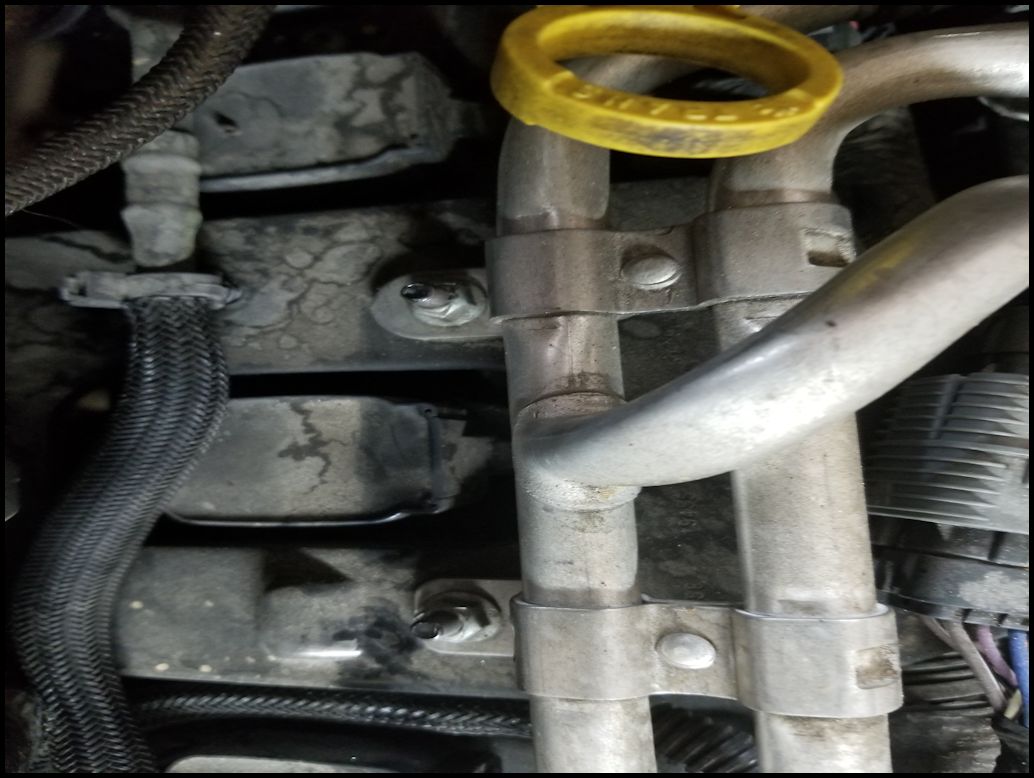
| 18. Remove the two (2) nuts holding the heater hard lines and bracket. You will need a 10mm socket and extension. The bracket doesn't move much, but it will be just enough to get the intake out from underneath it. |
 |
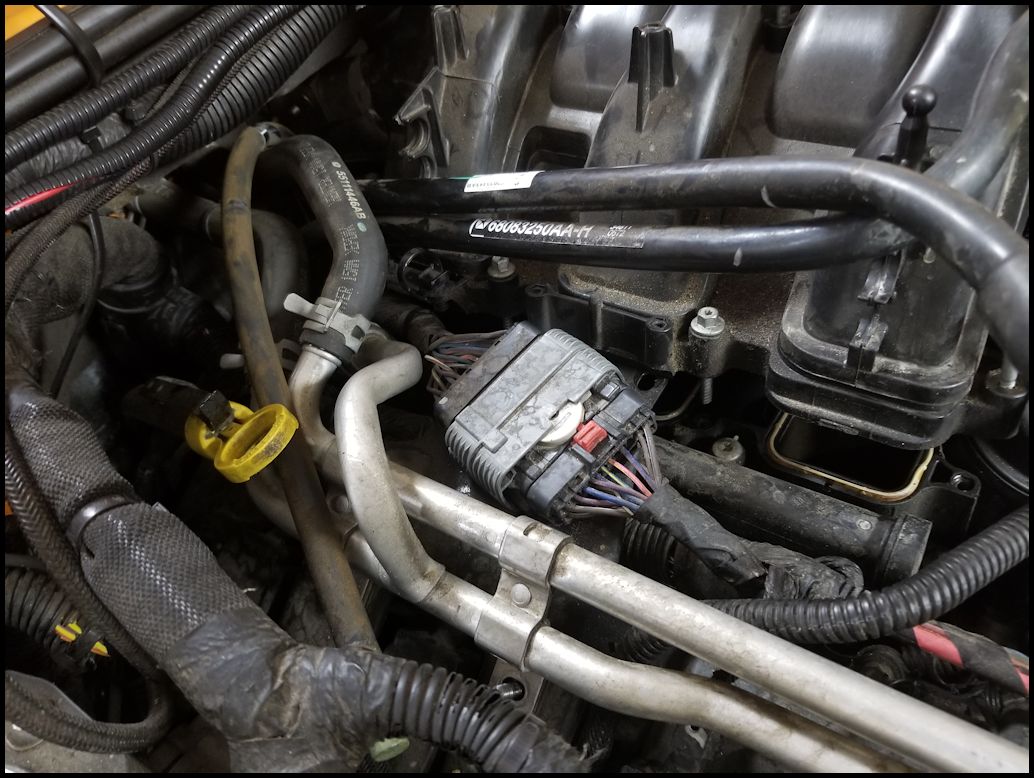
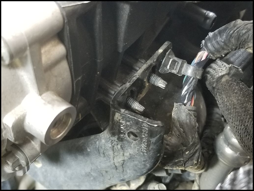
| 19. Remove the two cable retainers for the large electrical connector from the lower intake. These are a pain to get to even with a trim removal tool. I ended up having to cut the back one to get the cable free from the upper intake. If you have zip ties with the christmas tree on them, you can just cut both of these and put new zip ties on before you reinstall the cable. You will have to zip tie the cable first and then push the pins into the reinstalled intake. Not enough room to do it the other way around. |
 |
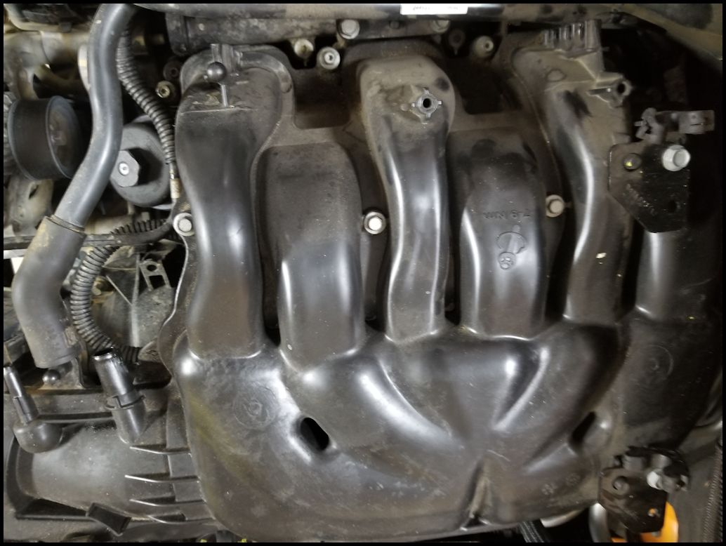
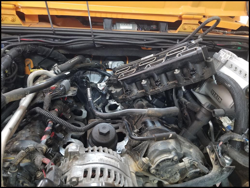
| 20. Lift the intake on the left side and get it out from underneath the bracket that you just unbolted. This is the point that you will find out if you unscrewed all the intake bolts. Once you have the intake above the bracket you will need to pull it up and to the left to get the four (4) studs clear of the two (2) brackets on the right side. You will need to push any hoses out of the way. It can be difficult to get out, but if it feels stuck recheck to see that your not hung up on something. |
 |
 |
 |
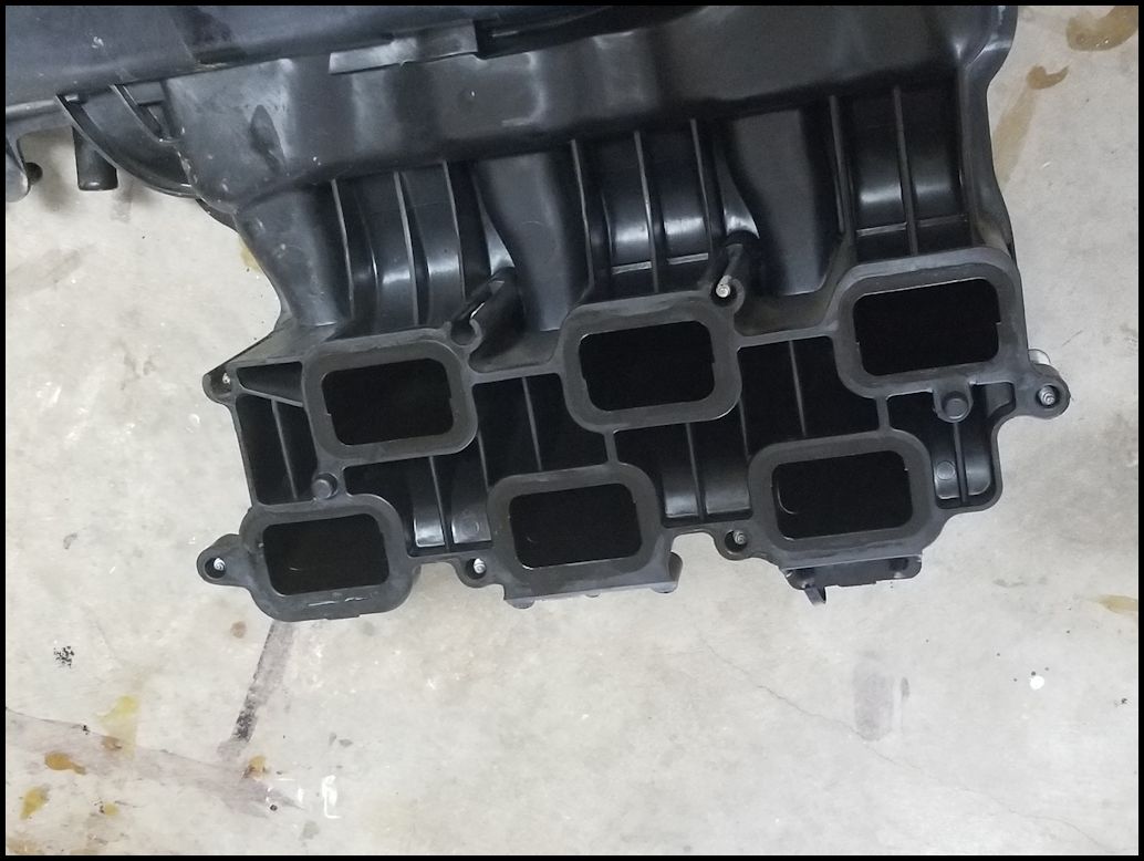
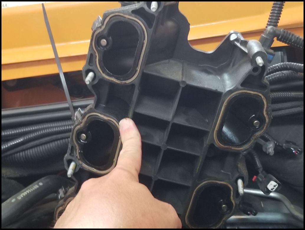
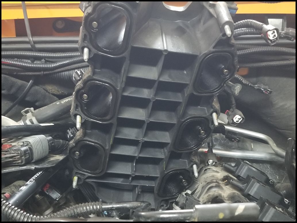
| 21. Once you have the intake clear, take a good look at it for any damage especially to the gasket seating surface. The six (6) gaskets should have remained in the lower intake assembly. You can also clean off the intake so that you don't have a chance of getting dirt down into the intake. |
 |
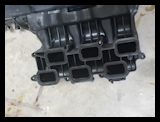 |
| 22. Check to make sure all six (6) gaskets are still in the lower intake or that you have all of the gaskets. Just a precaution against one falling into the lower intake. |
 |
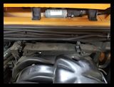
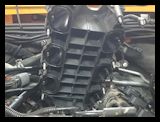
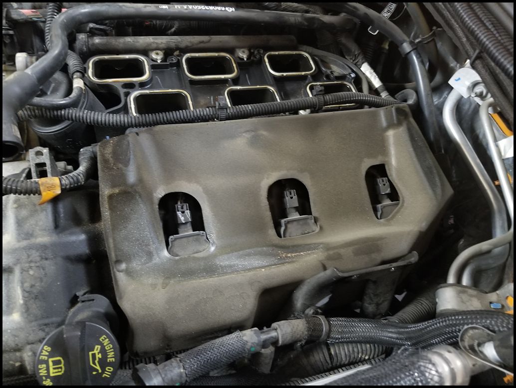
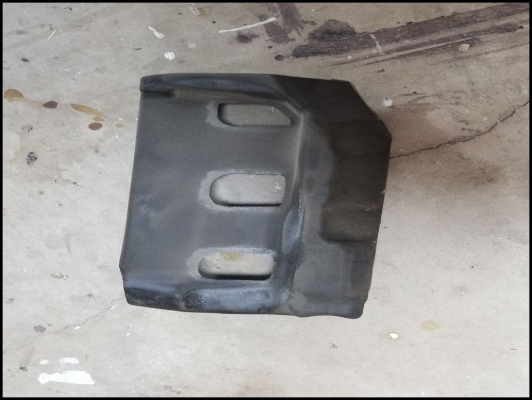
| 23. Remove the silencer foam from the right side of the engine. It should just lift up and out. |
 |
 |
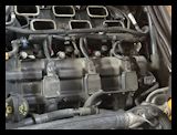 |
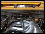
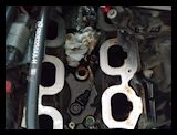
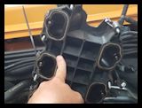
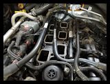
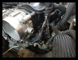
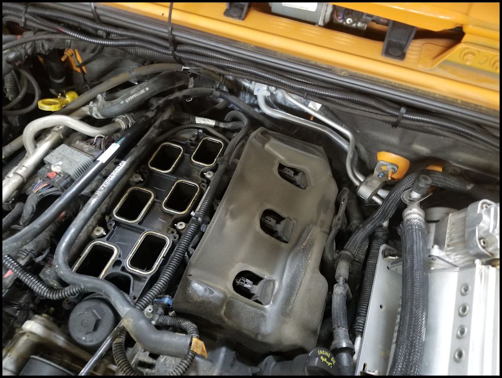
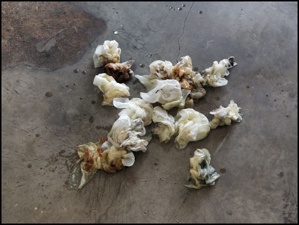
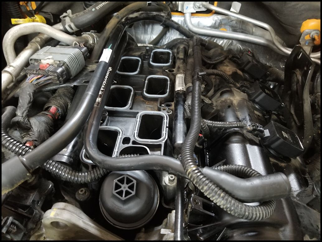
| 24. Cover the lower intake openings with some blue painters tape to keep any debris out of the intake. You can clearly see one of the valves, so it doesn't take much to get debris in there. |
 |
| |
| Remove Lower Intake: |
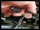
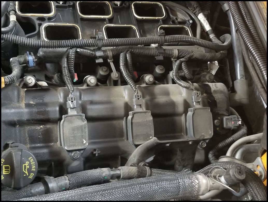
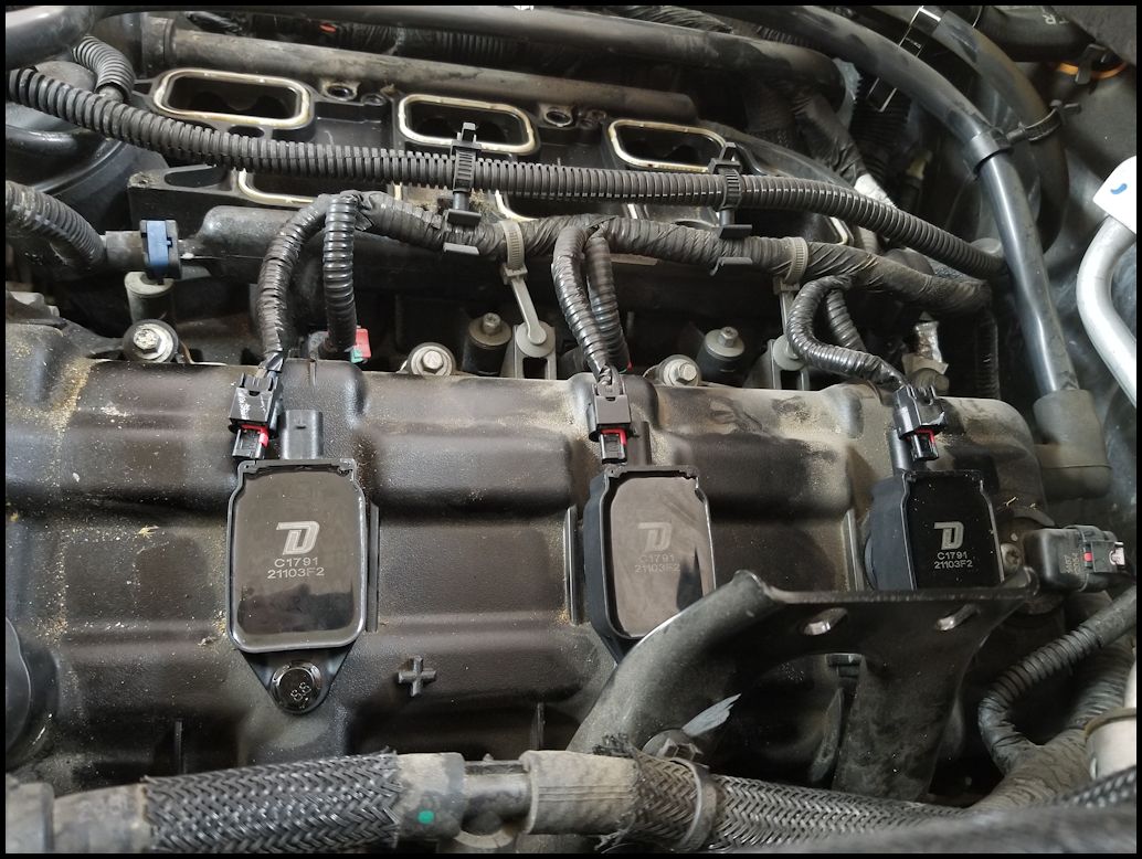
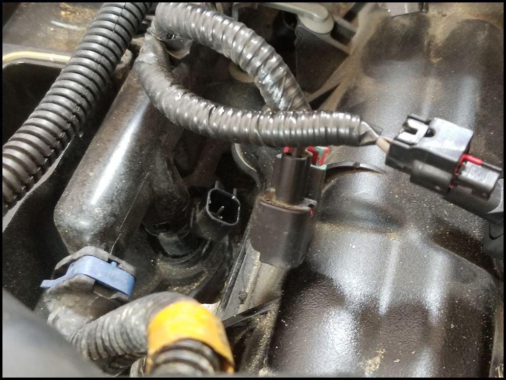
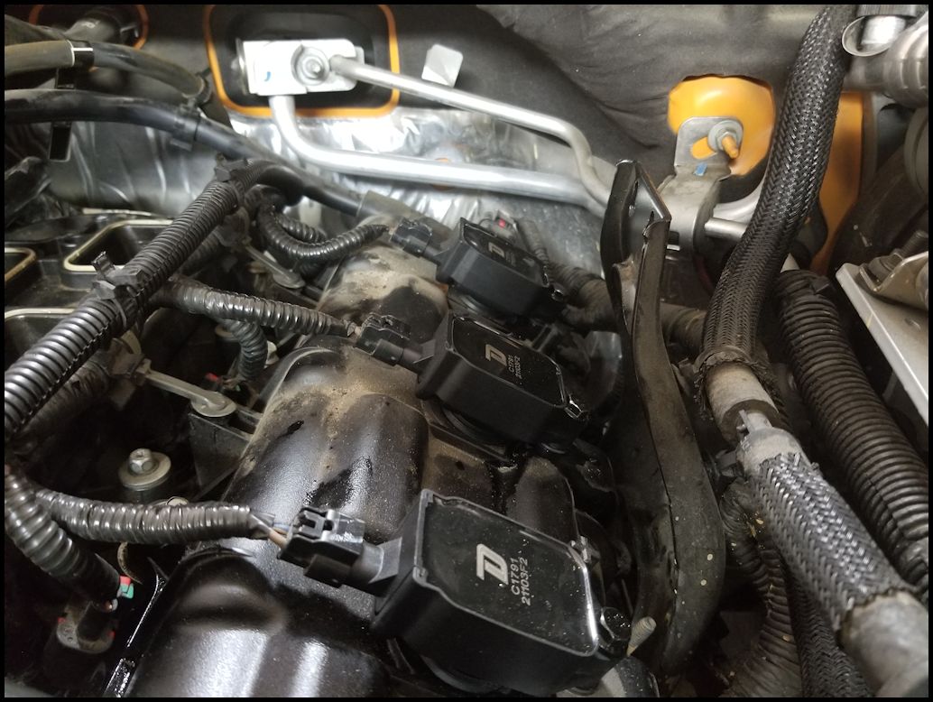
| 25. Unplug the three (3) coil pack connector on the right side of the engine. Press down on the tab and pull the connector out. |
 |
 |
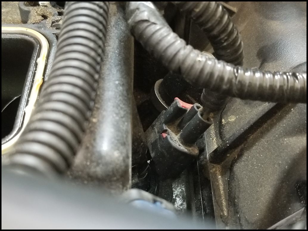
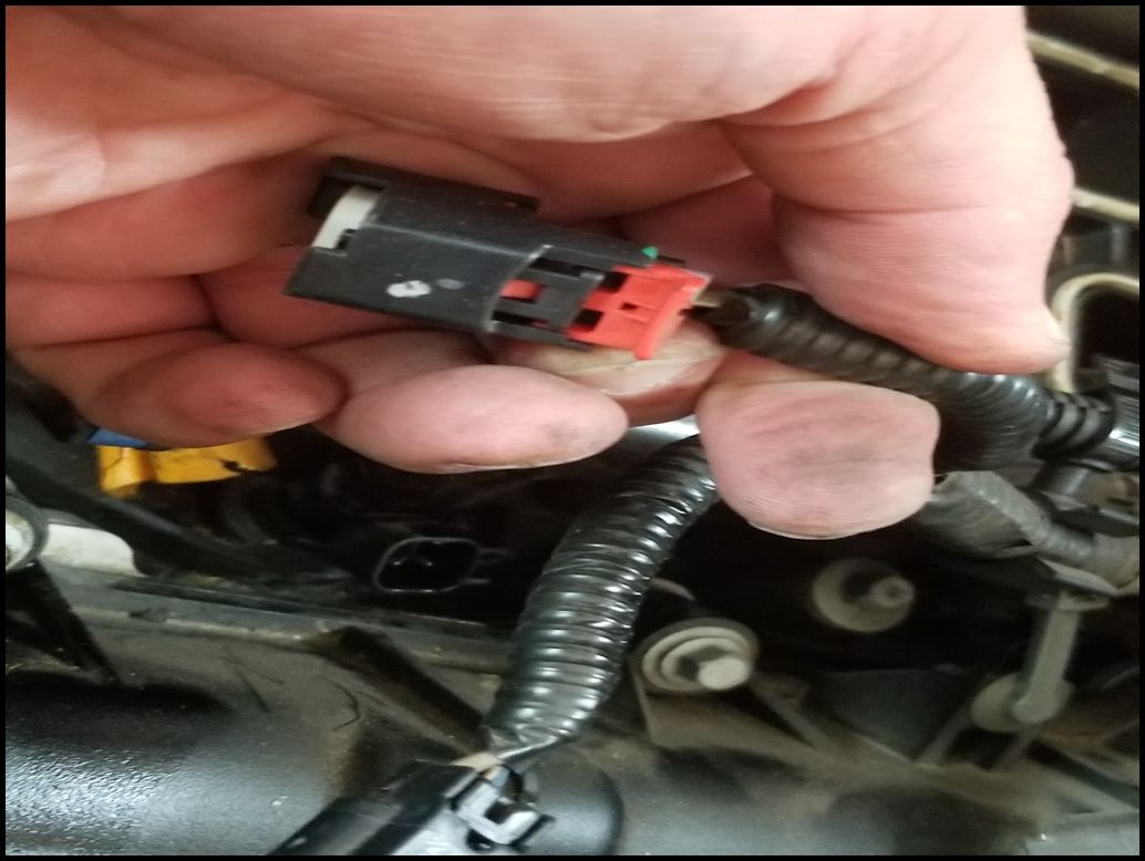
| 26. Disconnect the three (3) fuel injector harness connectors on the left side of the engine. Pull up the red tab on the connector then press down on the black tab pulling the connector out of the injector. This can be a little difficult due to limited room. You do not need to do this to the connectors on the right side, they will come off with the lower intake. |
 |
 |
 |
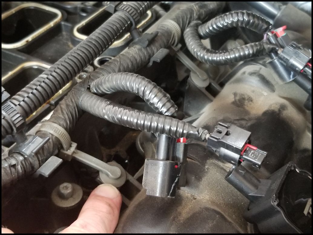
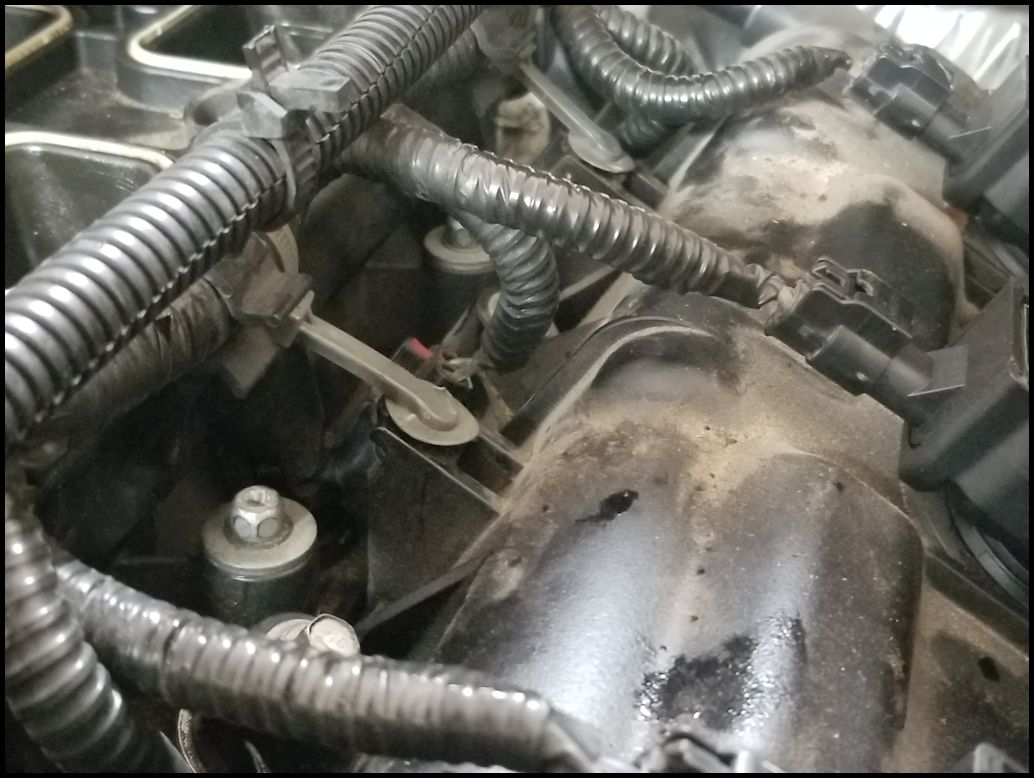
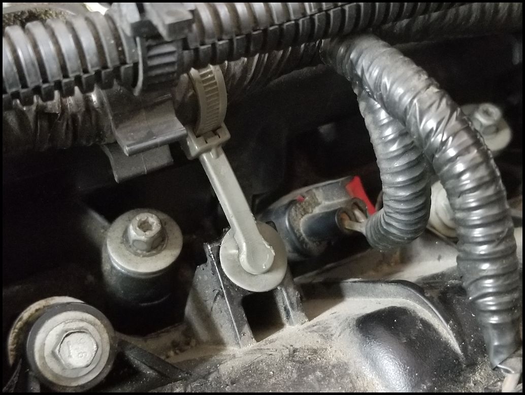
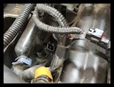 |
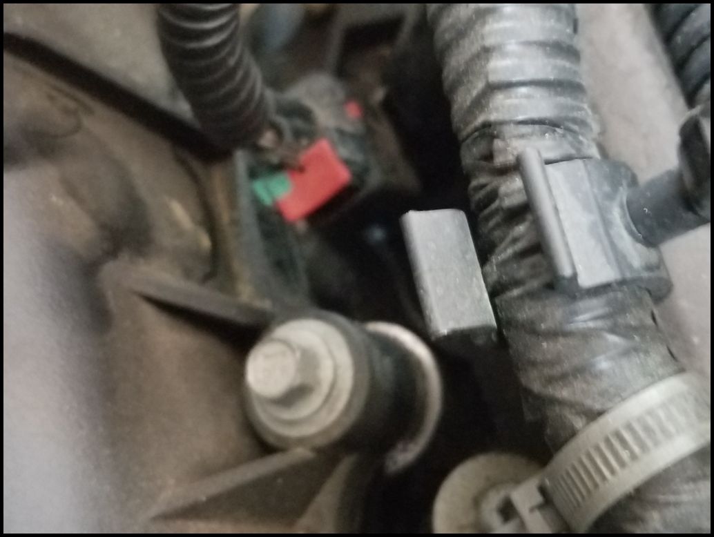
| 27. Undo the two (2) harness holders. These are the grey straps that attach the injector and coil pack harness to the valve cover. You will need a trim removal tool to pry these up and out of the valve cover. |
 |
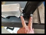
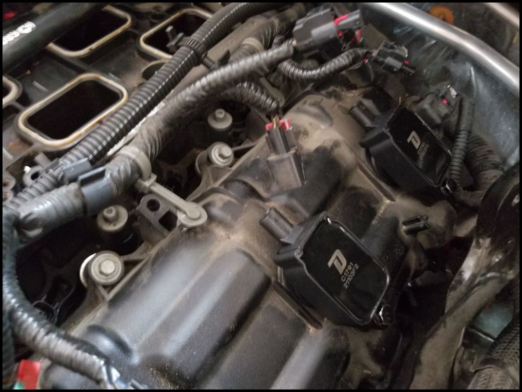
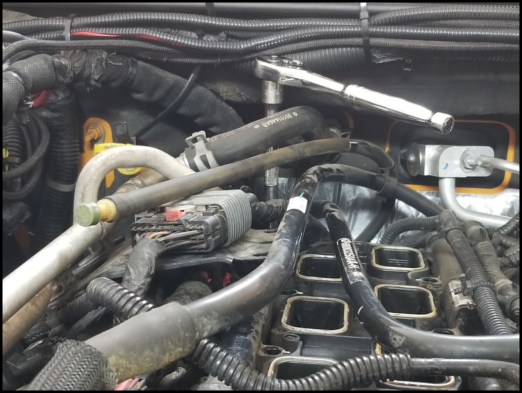
| 28. Remove the eight (8) bolts holding the lower intake to the block. There are four (4) on the left and four (4) on the right. You will need a 8mm socket and extension. |
Two on right side are near the straps you just removed.
|
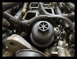
Two right in front on either side of the oil filter housing
|
Two on each side of the bracket for the heater hard lines.
|
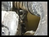
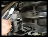
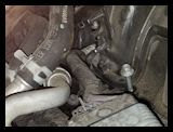
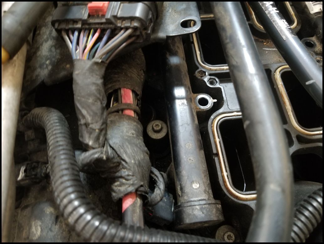
| The last two (2) bolts are back in behind the lower intake. The left is a real pain to get to because of all the hoses in the way. You will need a 8mm socket and a long extension. A wobble extension is worth the investment here. |
 |
 |
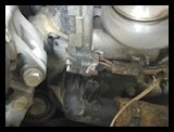
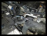
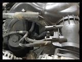
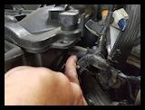
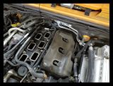
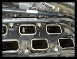
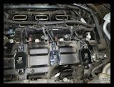
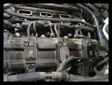
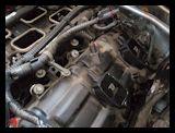
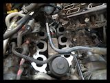
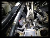
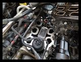
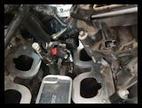
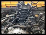
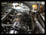
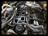
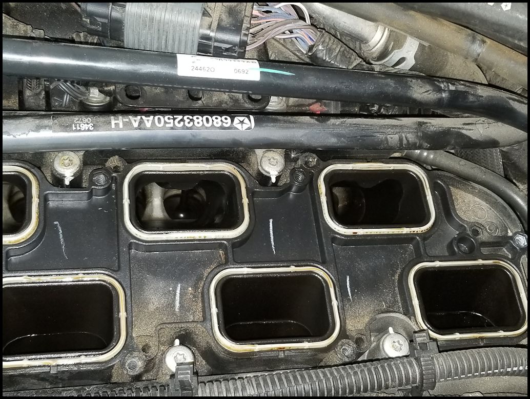
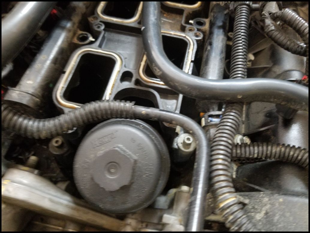
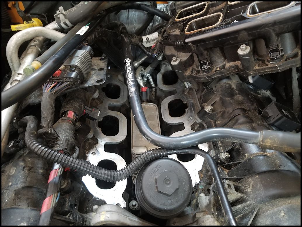
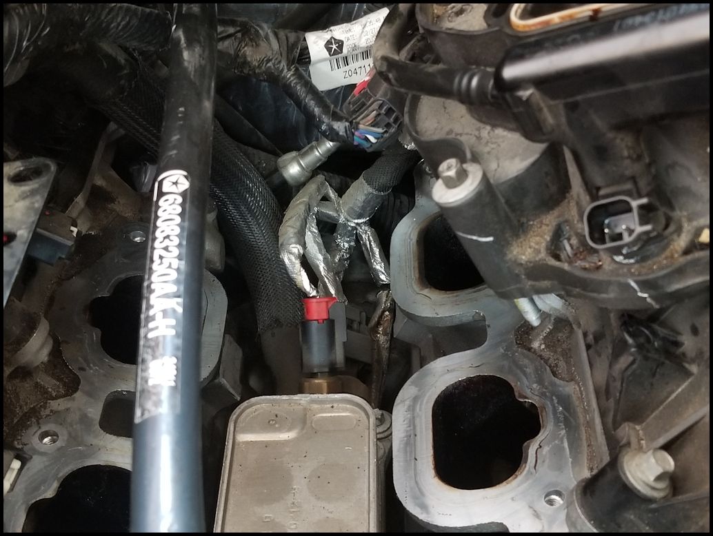
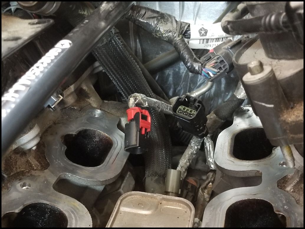
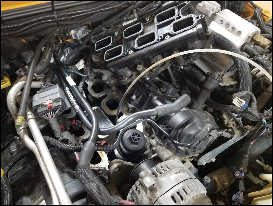
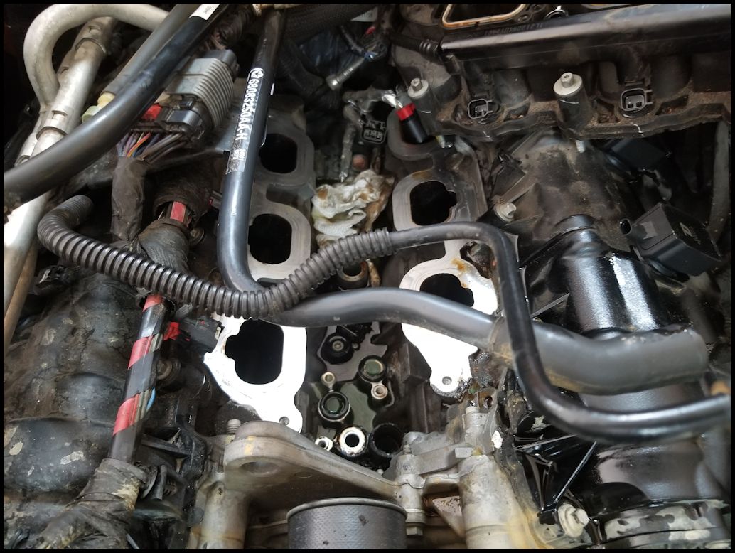
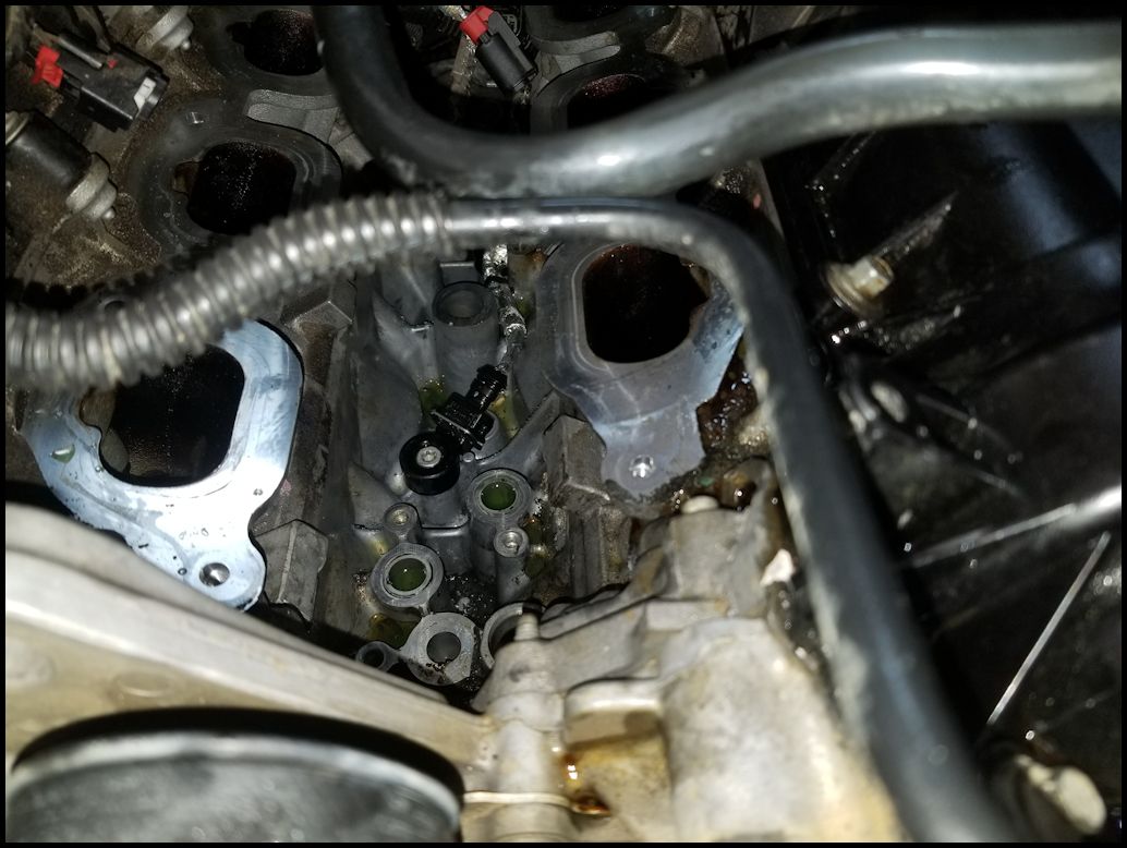
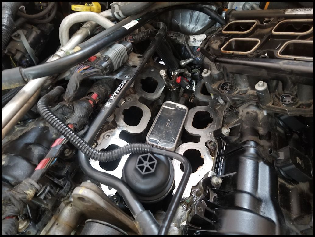
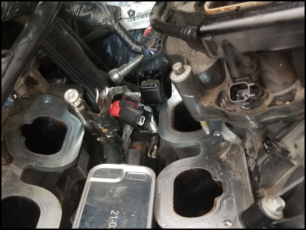
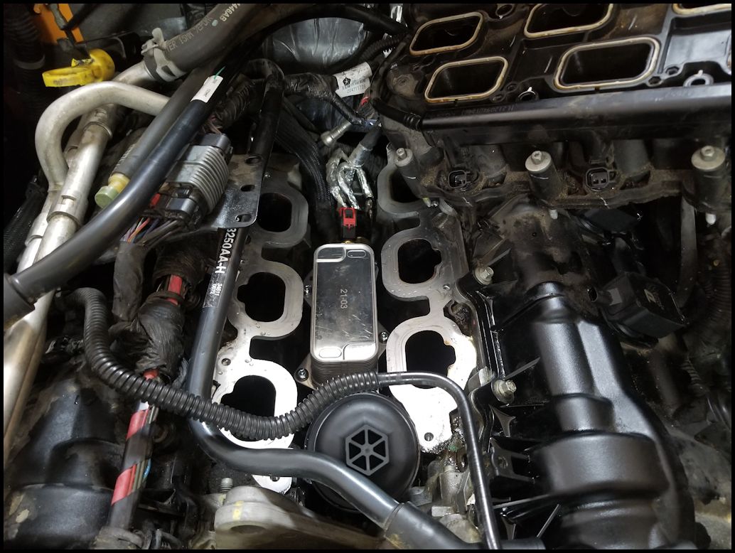
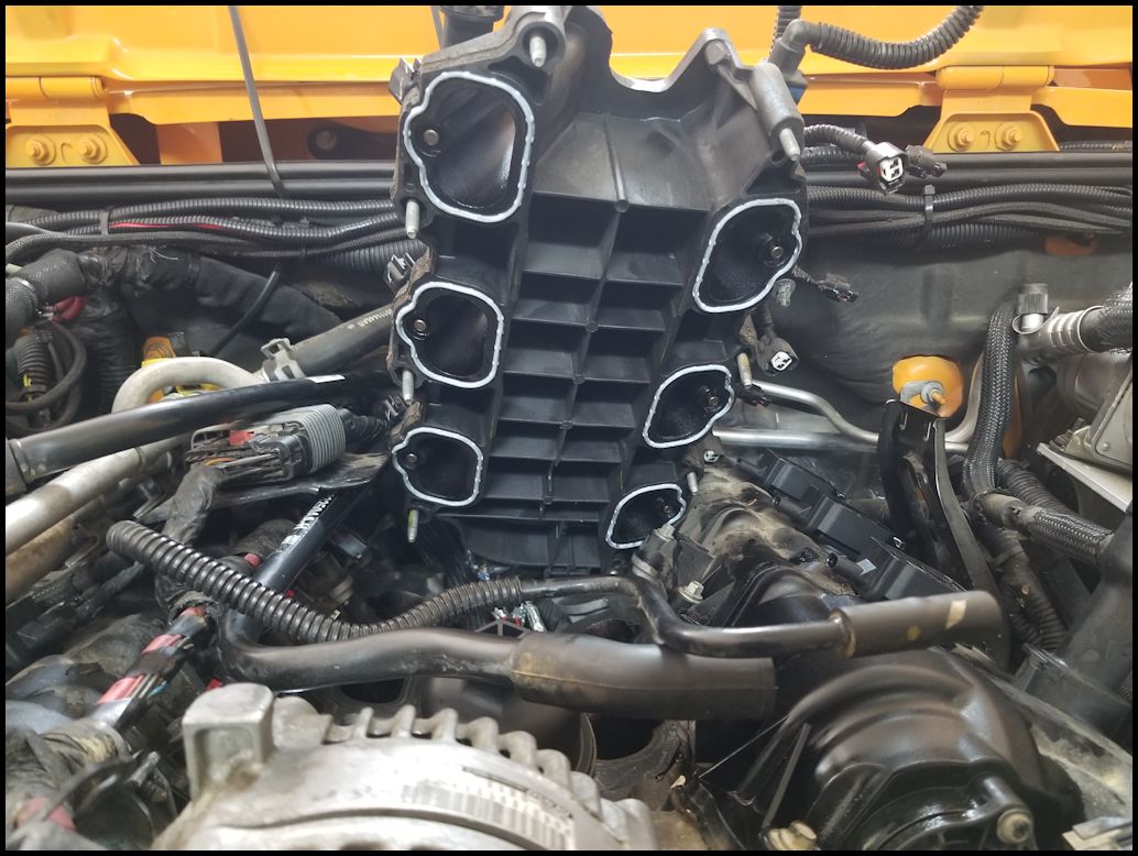
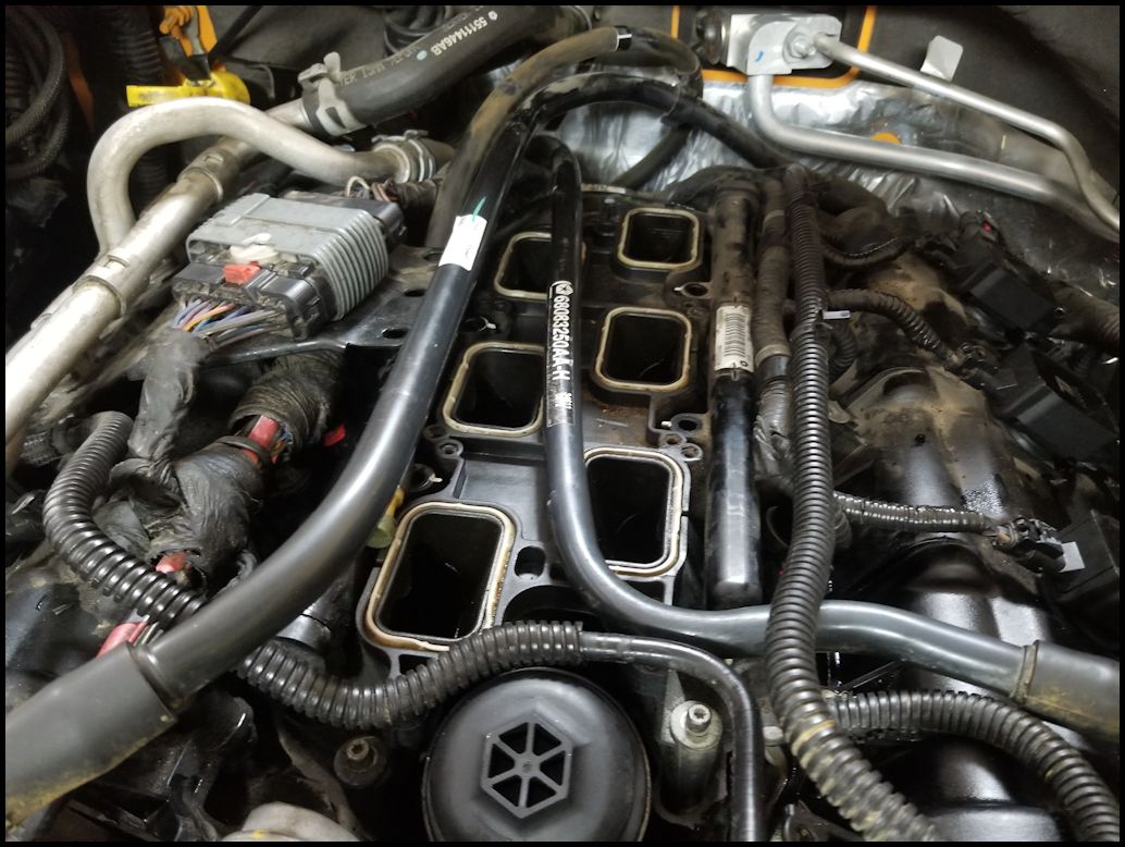
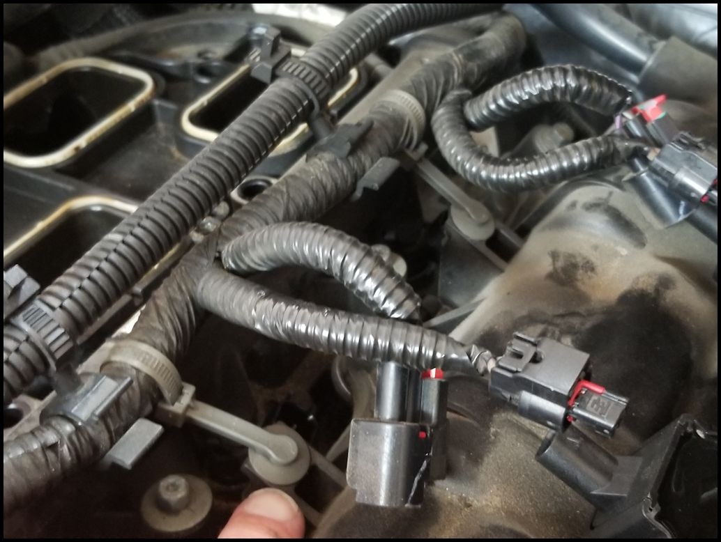
| 29. Before you do this step read the next line. Lift the lower intake up and rotate it to the side. You will still have fuel rail lines attached, so it doesn't go very far, but it will give you enough access to the oil cooler assembly. I recommend covering the intake and exhaust valve openings with blue painters tape. |
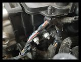
 |
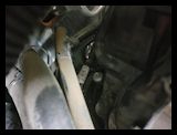
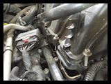
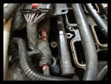
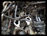
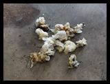
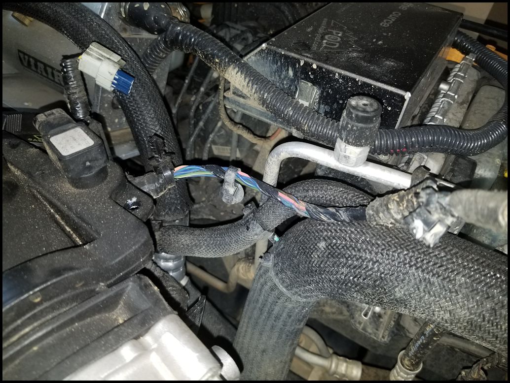
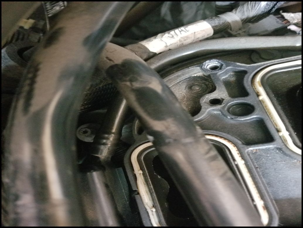
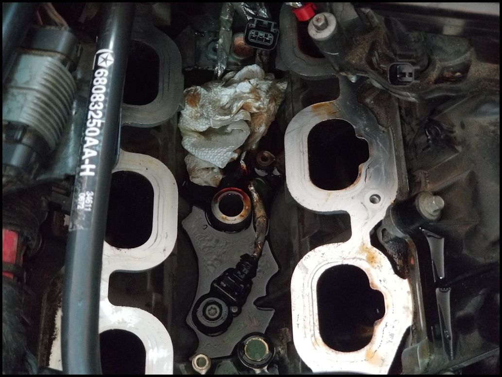
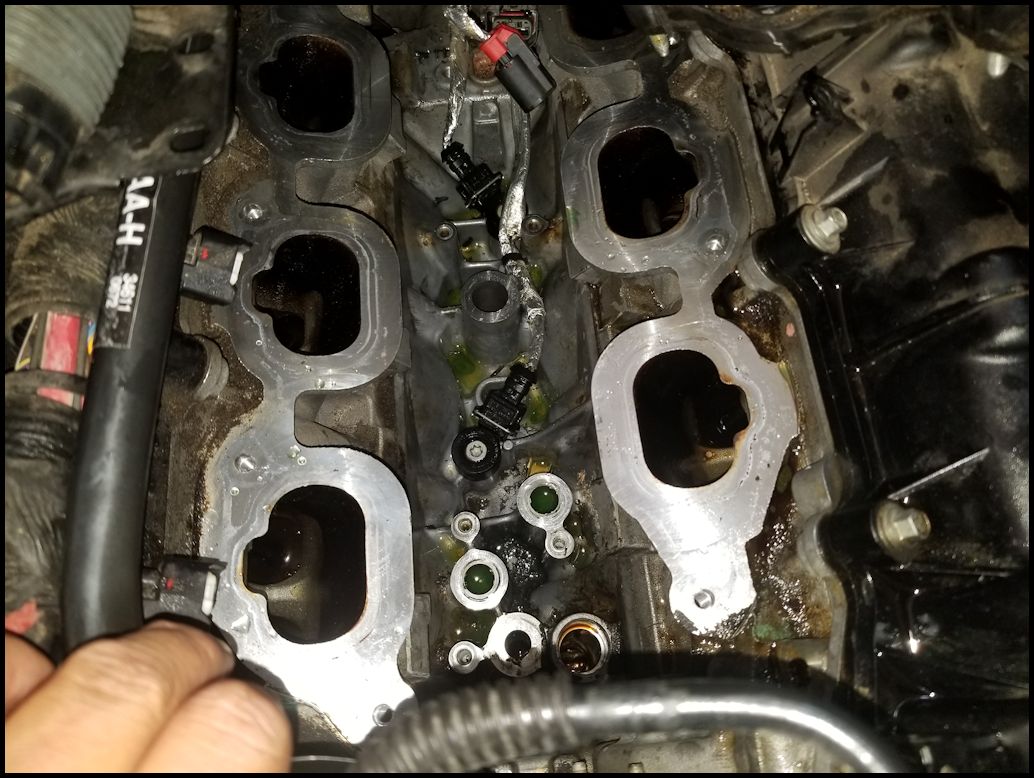
This is where I ran into problems. On the left side of the picture you will see a harness running underneath the bracket for the heater hard lines. The plastic shroud for this harness disintergrated as I removed the lower intake housing. Guess where all that debris went. Yep, right into those three (3) gaping holes and on top of the intake and exhaust valves. I got extremely lucky and all the valves were closed on that side of the engine. I spent the next couple hours carefully sucking and tweezing plastic parts out of the intake and exhaust valves. I had to use my little shop vac and a computer cleaning kit to get down into those openings.
WARNING: DO NOT use compressed air to blow out the openings, you can force debris down into the cylinder. |
 |
| |
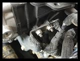
| Oil cooler removal and installation: |
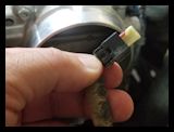
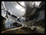
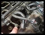
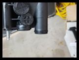
| 30. Disconnect the oil pressure and temperature sensors from the back side of the oil cooler. Pull up the red tab to unlock the release button. |
|
 |
 |
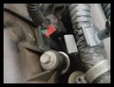
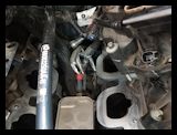
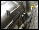
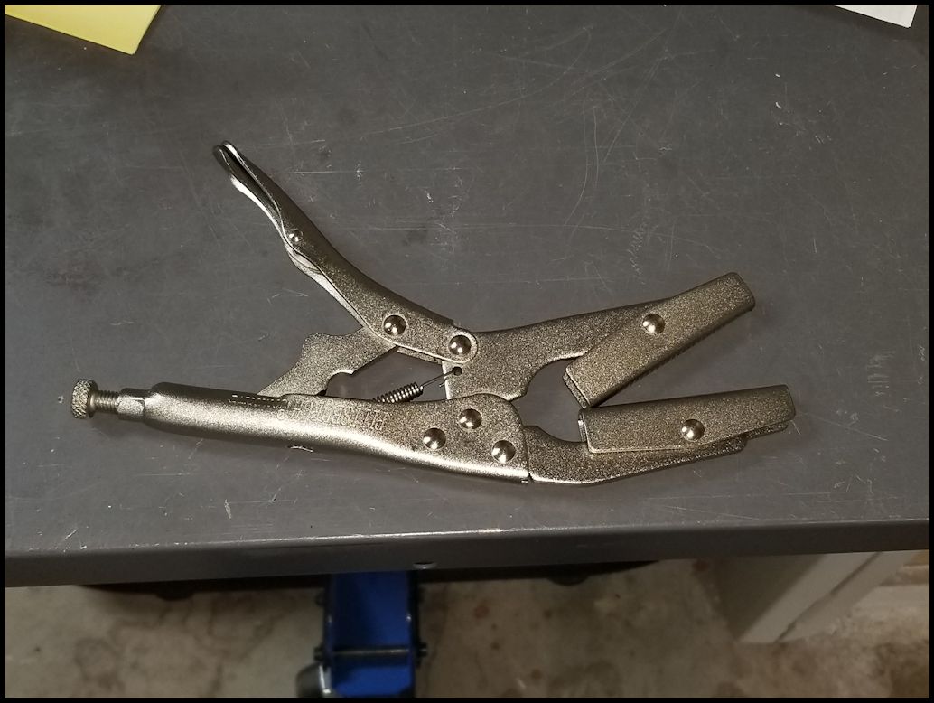
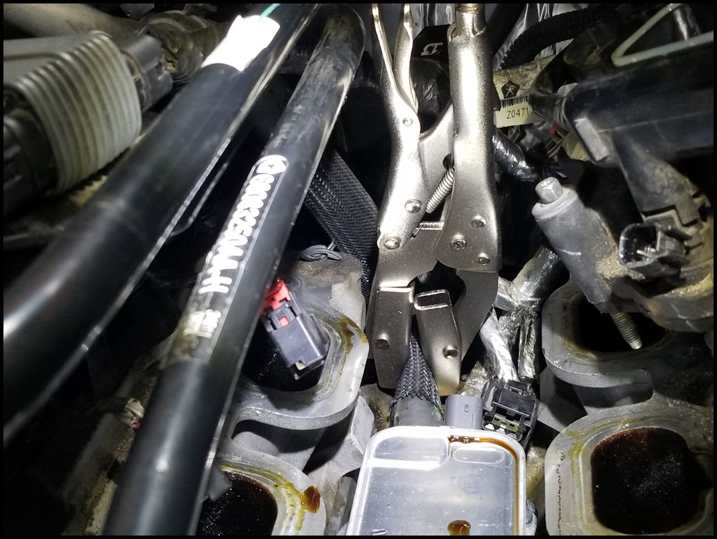
| 31. Pinch off the coolant line on the back side of the oil cooler with a hose pinch pliers. I was able to use a pair of needle nose vice grips to pinch off the line. You may get some leakage past it, just be careful you don't over clamp the line. |
 |
 |
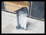
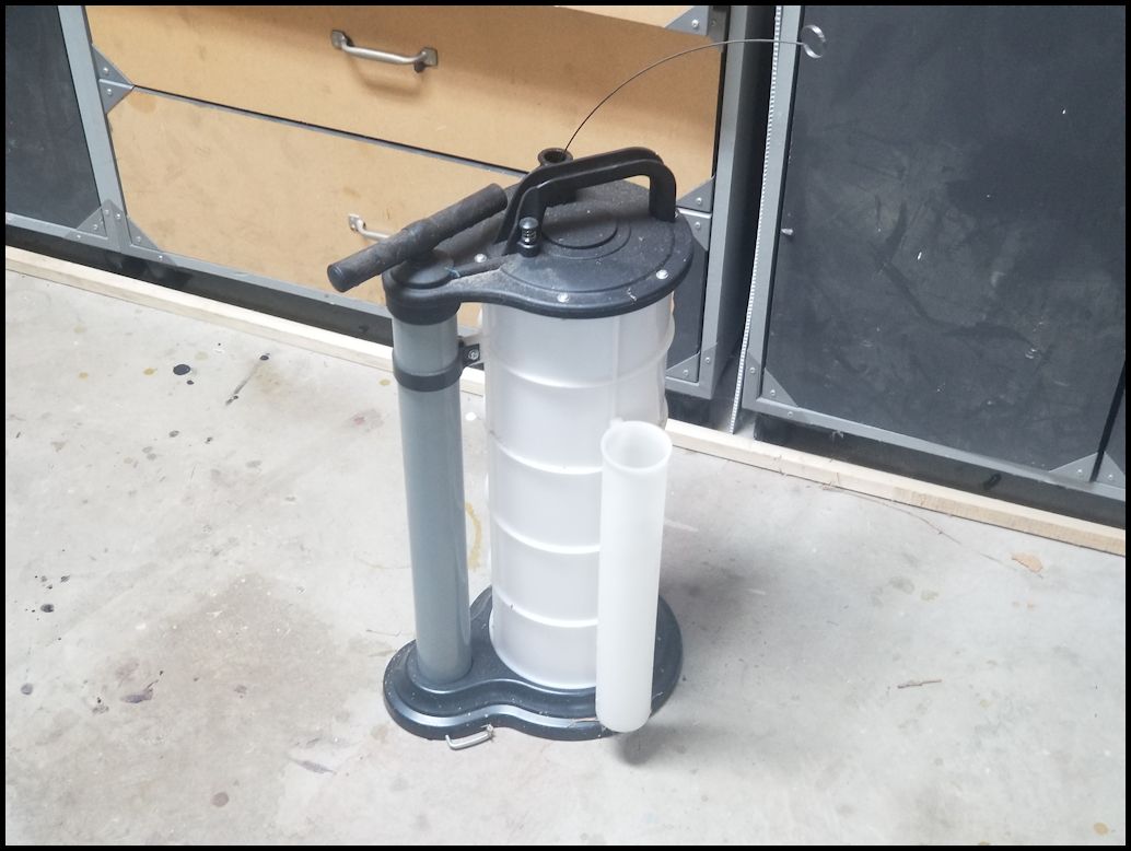
| 32. If you have a fluid extractor, this would be a good time to use it and try to syphon the oil and coolant that has leaked out and is sitting around the oil cooler and in the valley between the two heads. |
 |
 |
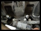
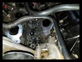
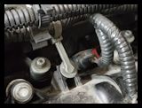
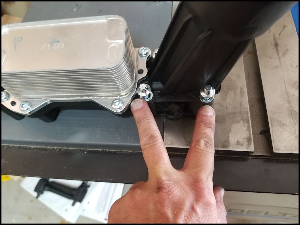
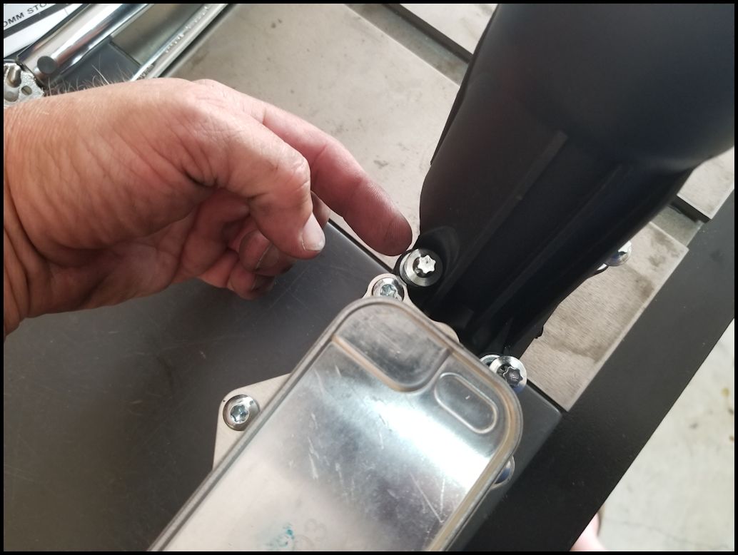
| 33. Loosen the five (5) bolts holding the oil cooler in place. It was difficult to get good pictures down into the cavity on either side of the oil cooler, but it's easy enough to show you on the new oil cooler. You will need a E8 inverted torx socket and extension. |
Rear bolts
|
Front left side bolts
|
Front right side bolt
|
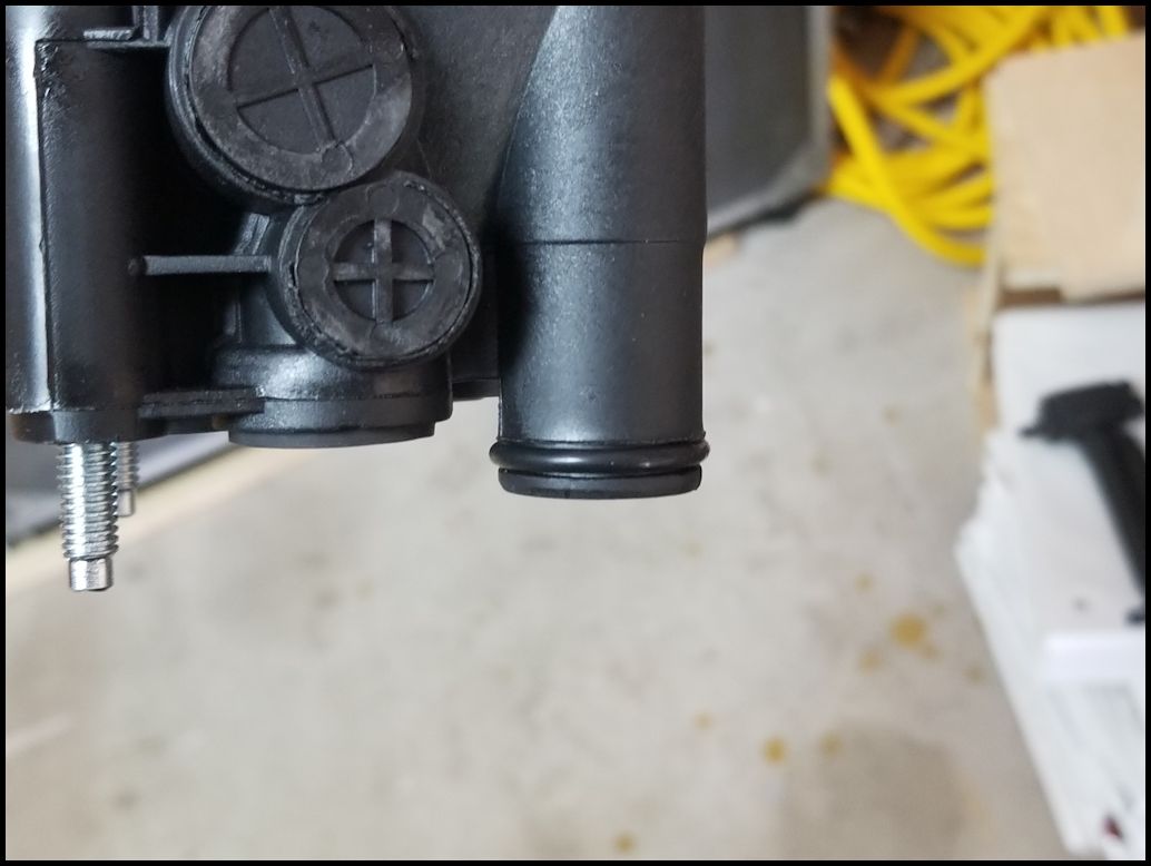
| 34. Pull the oil cooler up and out. On the front is a tube for the oil to return to the engine block. This has a rubber o-ring on it and will require a little extra force when you lift. |
 |
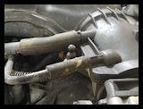
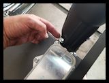
| 35. Remove the clamp holding the hose to the oil cooler with a pair of pliers. They do make a special tool for these types of clamps, but you can get it with a pair of pliers. |
|
| 36. Remove the hose from the oil cooler. You will get some coolant leakage out of the oil cooler. Putting a drip pan under the engine is worthless, the coolant goes all directions, so just clean it up with some rags. |
|
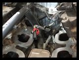
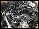
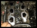
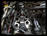
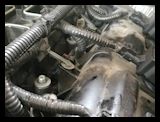
| 37. Clean out all the oil and coolant from the valley between the heads. I was surprised at how much there was trapped in this little area. It was a couple inches deep and easily over 1/2 quart of fluid. Clean off the mating surfaces on the block. |
 |
 |
 |
 |
| Like I said it makes a mess getting all of the oil and coolant out of the valley. This is even after I used the extractor to get stuff out. This does need to be disposed of properly since it's anti-freeze and oil. |
 |
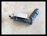
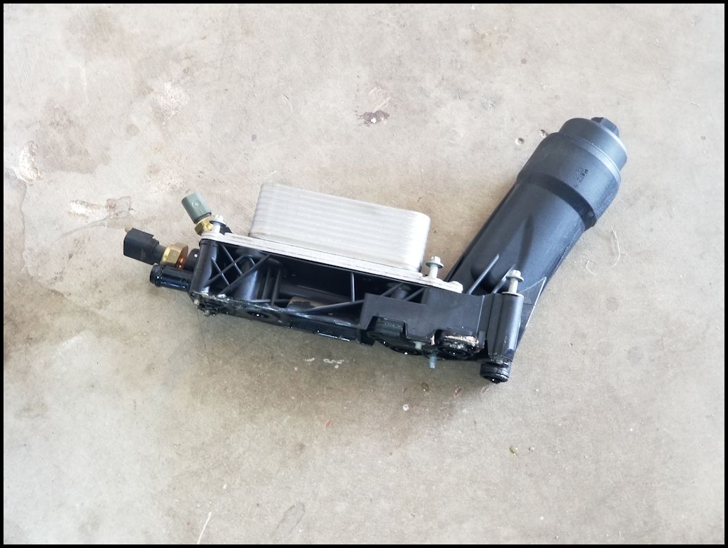
| This is the remains of the old cooler. You can see where the coolant was leaking out at the bottom of the cooler. Check to make sure you have all the o-rings out. There should be four (4) o-rings in the base, and one on the tube coming down off the base. |
 |
 |
 |
 |
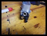
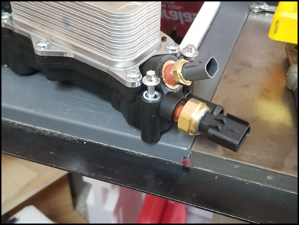
| 38. If your cooler doesn't have the sensors installed, you will need to install the new sensors into the back of the new oil cooler. I used an adjustable wrench to install these and didn't check the actual wrench size. |
 |
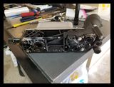
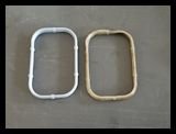
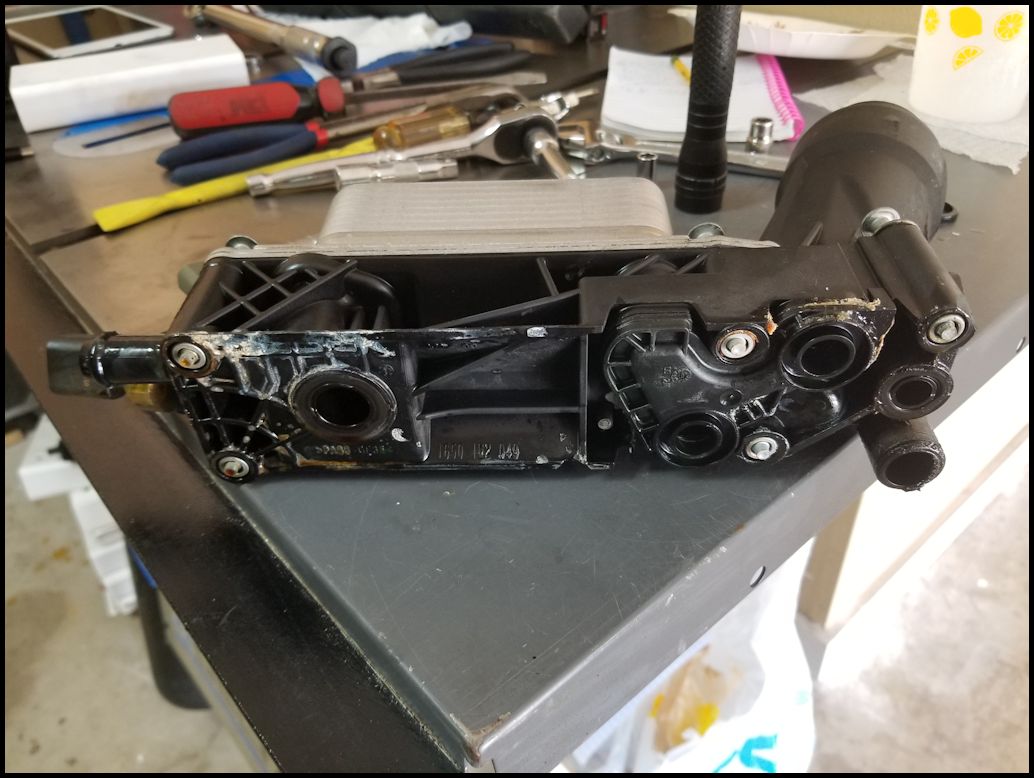
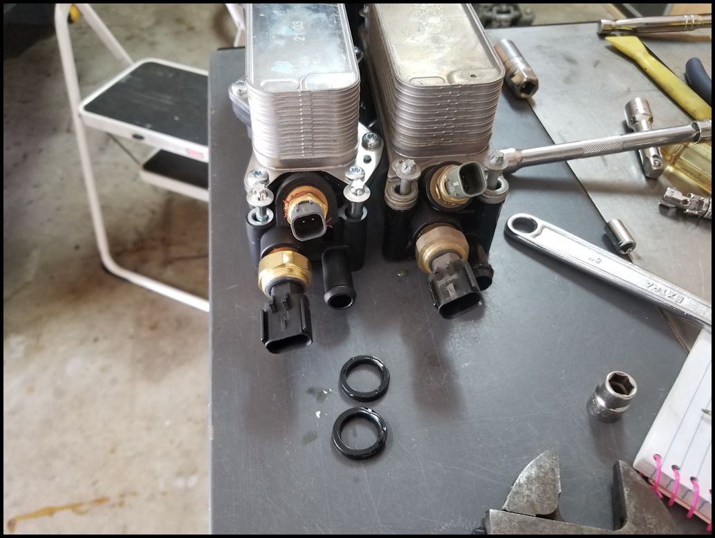
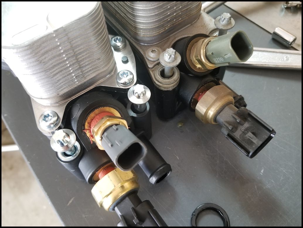
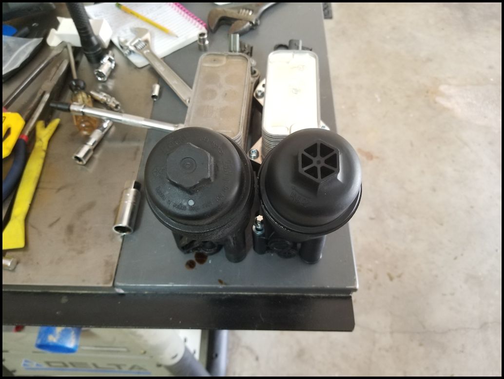
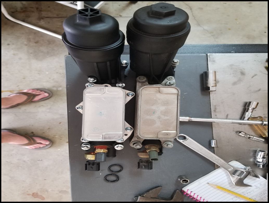
| Comparison between the 2012/2013 oil cooler and the 2014 oil cooler. The big changes were the backflow valve assembly that they moved into the oil filter cap instead of having the problematic stick in the center of the oil filter housing. They also changed the oil cooler giving it a more robust mounting plate and additional thinner cooling plates. The cooler did get a little thinner in width. |
Different sensor angle (flatter)
|
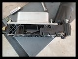
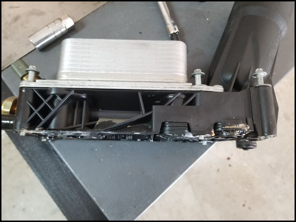
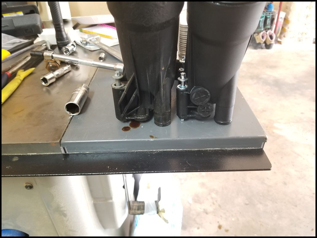
The 2014 cooler is bolted to the body and the mounting bolts only go through the body. The 2012 bolts went through the plate for the oil cooler.
|
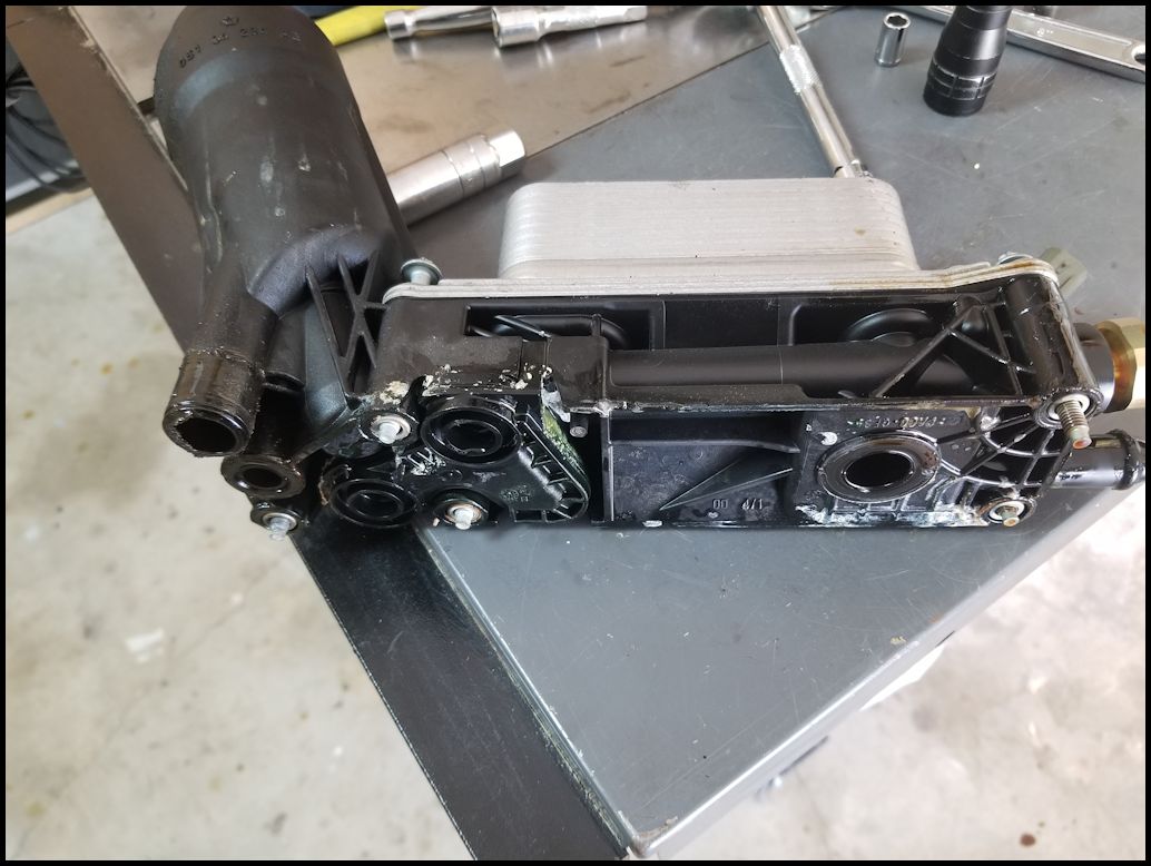
Different oil filter caps, the internals are different with how the bypass valve is installed.
|
2014 oil cooler is smaller, but has more plates than the 2012. The oil cooler bolting is more robust.
|
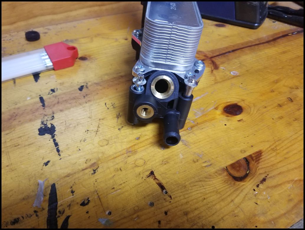
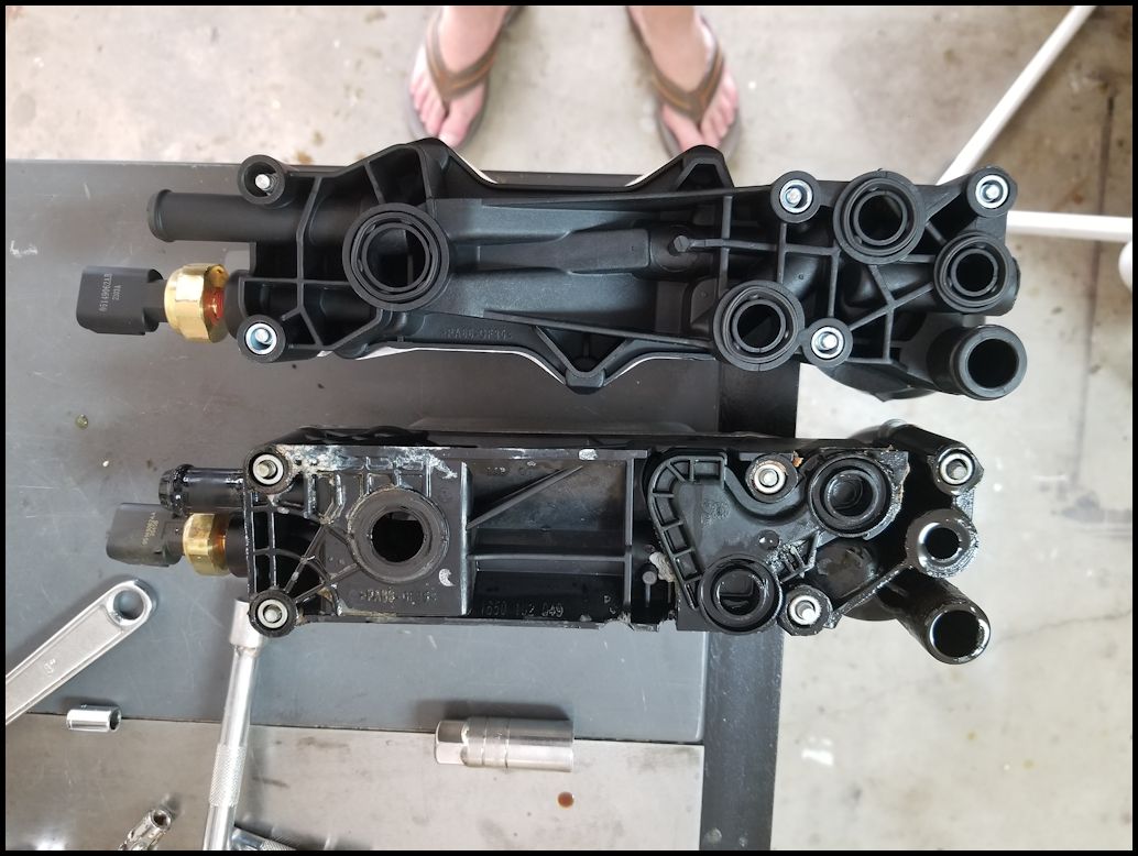
Porting is different
|
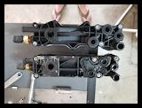
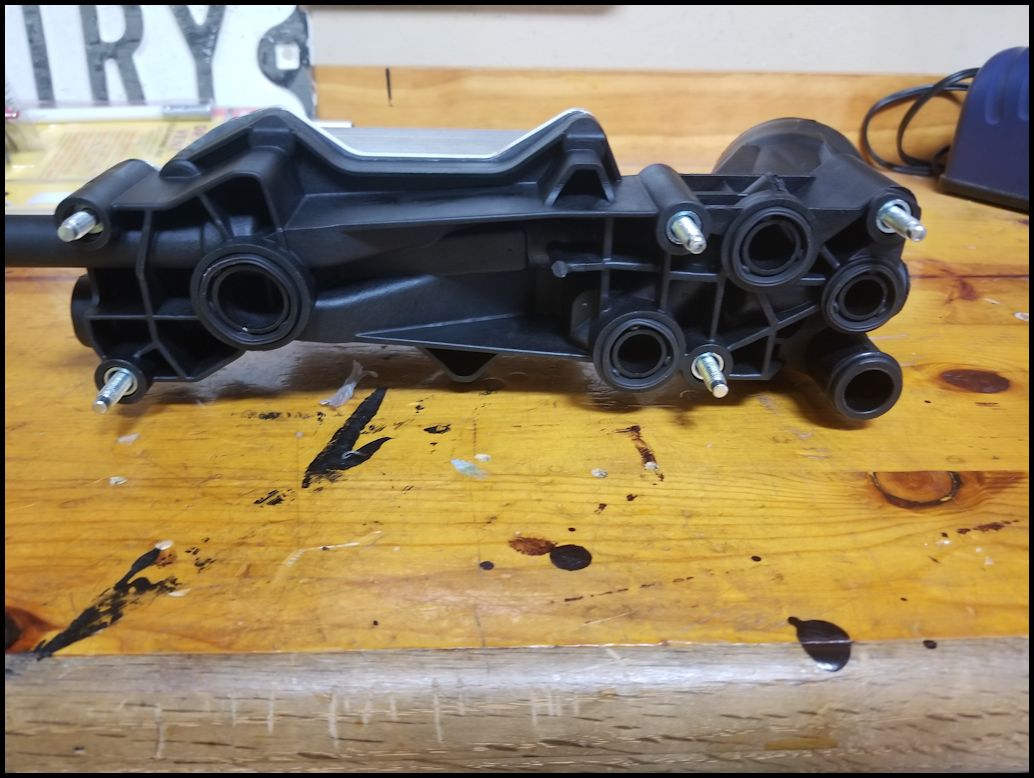
Bolt pattern, inlets, and outlets are the same. Just the molding is different.
|
| 39. Make sure that the four (4) o-rings are installed in the bottom of the new oil cooler, and that they o-ring is installed on the tube. |
|
| 40. Reinstall the coolant line to the back of the oil cooler. Reinstall the clamp. |
|
|
| 41. Install the new cooler. Line up the tube on the front of the oil cooler with the hole in the block. Once you have the oil cooler down and flush screw in all of the bolts to get them started. Do not tighten any down until you have all of them aligned and started. You will need a E8 inverted torx socket and extension. Snug the bolts up and then tighten in a criss-cross pattern. |
 |
| 42. Remove the hose pinch off pliers. |
|
| 43. Reconnect the oil temperature and oil pressure sensor connectors. Make sure you push the red locking tab back in. |
 |
 |
| Note: Make sure you have all your bolts tight, hoses on, clamps in place, tools removed, sensors reconnected and locking tabs in place before you continue. Sucks taking everything back apart to connect something you forgot.... Don't ask. |
| |
| Installing Lower Intake Assembly: |
| 44. Remove the lower intake to block gaskets from the bottom side of the lower intake assembly. Check to make sure the bottom of the lower intake is clean. You will need an o-ring pick, or scribe to get these out. |
 |
 |
| 45. Find the lower intake to block gaskets. Thes are the ones with the hump on one side. Make sure you have 6 of them. Install the gaskets into the lower intake. The gaskets have bumps on them that will hold them in place in the slot on the intake. |
 |
 |
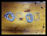
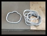
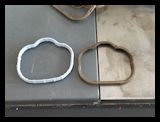
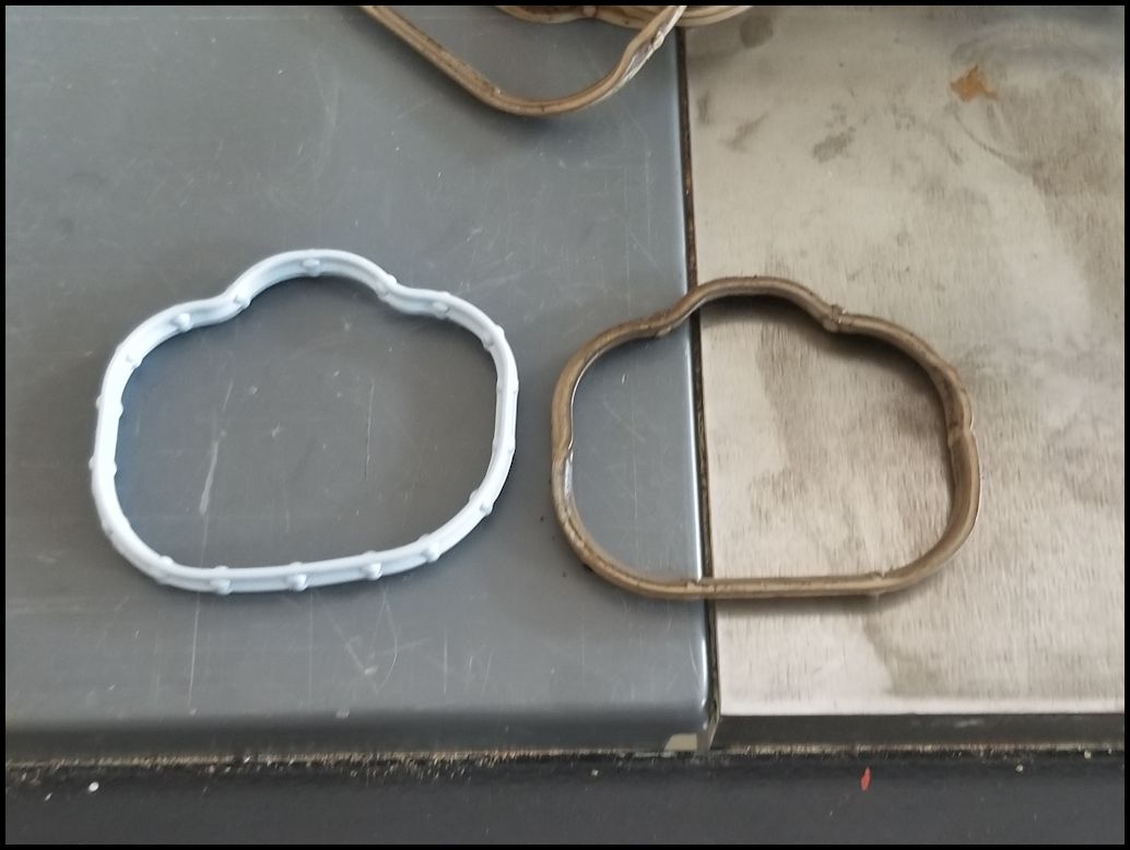
| Comparison of the old and new gaskets. The old were definately harder than then the new gaskets, but would have still been serviceable in an emergency. Always better to replace gaskets with new ones, its easier than having to take it apart again to do it right the second time. |
 |
| 46. Remove the blue painters tape from the block if you installed it earlier. |
| 47. Reinstall the eight (8) bolts holding the lower intake to the block. There are four (4) on the left and four (4) on the right. You will need a 8mm socket and extension. I snugged them up and then tightened in a criss-cross pattern. |
Two on right side are near the straps you just removed. |
Two right in front on either side of the oil filter housing |
Two on each side of the bracket for the heater hard lines. |
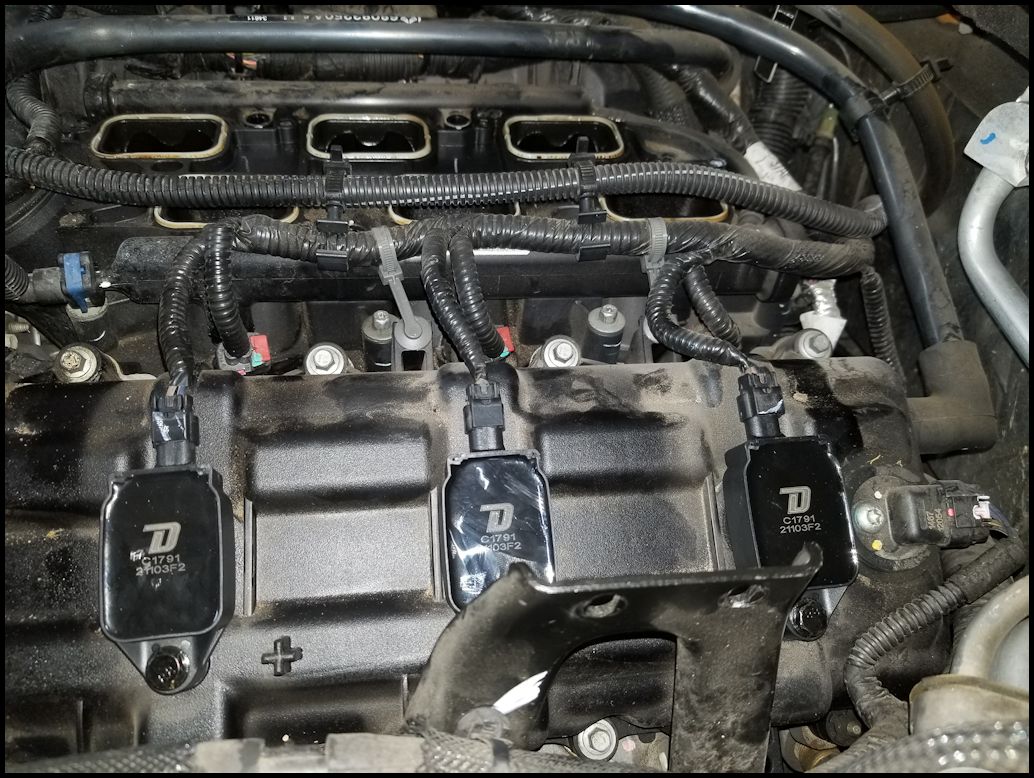
| 48. Reconnect the three (3) fuel injector harness connectors on the right side of the engine. Push the red locking tab back in. This can be a little difficult due to limited room. You will need to do the same thing for the three (3) fuel injector harness connectors on the left side. Plug the three (3) coil pack connector on the right side of the engine. |
 |
| 49. Reinstall the two (2) harness holders. These are the grey straps that attach the injector and coil pack harness to the valve cover. |
 |
 |
| |
| Reinstall the upper intake assembly: |
| 50. Remove the blue painters tape if you installed it. Remove the six (6) gaskets from the top of the lower intake. You will need an o-ring pick, or scribe to get these out. |
 |
| 51. Install the new gaskets into the top of the lower intake assembly. These are the rectangular ones. The gaskets have bumps on them that will hold them in place in the slot on the intake. |
 |
 |
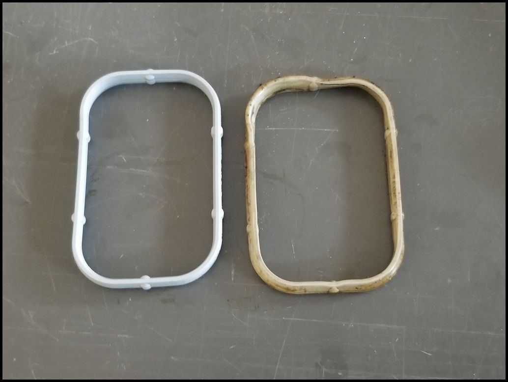
| Comparison of the old and new gaskets. Just like the previous gaskets, the old ones were definately harder than then the new gaskets, but would have still been serviceable in an emergency. Always better to replace gaskets with new ones, its easier than having to take it apart again to do it right the second time. |
 |
| 52. Reinstall the silencer foam from the right side of the engine. |
|
|
|
| 53. Reinstall the upper intake assembly. You will need to slide the four (4) studs into the brackets on the right side and then get the intake under the bracket on the left side. Screw down the seven (7) bolts that hold the upper intake to the lower intake. You will need a 8mm socket and long extension. I did the center first (front, back, middle), then the four (4) on the left side (front, back, middles). |
 |
| 54. Reinstall the four (4) nuts on the studs that hold the upper intake to the brackets on right side of the upper intake. You will need a 10mm socket or combo wrench. |
 |
 |
| 55. Reinstall the two (2) bolts holding the bracket for a large electrical connector and the heater hose hard lines. The bracket is bolted to the intake above the fuel rail on the left side of the intake between two of the intake bolts. You will need a 8mm socket and extension. |
|
| 56. Reinstall the two (2) nuts holding the heater hard lines and bracket. You will need a 10mm socket and extension. |
|
| 57. Reinstall the two cable retainers for the large electrical connector from the lower intake. If you cut these earlier you will need to have zip ties with the christmas tree on them. You will have to zip tie the cable first and then push the pins into the reinstalled intake. Not enough room to do it the other way around. |
|
| 58. Reconnect the two (2) vacuum lines on the left side of the throttle body intake. These just push onto the fittings. |
 |
 |
| 59. Reconnect the crankcase line to the air intake box. This just pushes onto the fitting. |
 |
| 60. Reconnect the throttle body connector and push the plastic clip over the tab below the throttle body opening. |
 |
 |
 |
| 61. Reconnect the MAP sensor connector. |
 |
 |
| 62. Reconnect the harness holders to the under side of the upper intake assembly by the MAP sensor. |
 |
| 63. Reinstall the brake booster vacuum line onto the fitting by the MAP sensor. If you don't do this not only will the engine sound funny, but you will have a hard time stopping when you back out of the garage. Don't ask... |
 |
| 64. Reinstall the vacuum lines and transmission breather lines into the bracket on the left side of the upper intake assembly. They just push into the holder. |
 |
| 65. Reinstall the sound insulation foam from the back side of the engine. Carefully wiggle the foam behind the intake and install the two retainers on top of the foam. |
|
 |
|
| 66. Reinstall the air intake tube from the filter box and throttle body. |
|
| 67. Reconnect the IAT sensor connector located underneath the air intake tube. Push in the red locking tab if your connector has it. |
|
|
| 68. Tighten the intake hose clamps on both ends of the intake tube. You will need a flat tip screwdriver or a 8mm socket. |
|
|
| 69. Reinstall the two bolts holding the intake to the radiator. You will need a 10mm socket. Reinstall the radiator overflow hose intothe bracket. |
|
|
|
| 70. Reconnect the battery cables. You will need a 10mm or 12mm socket. I have a dual battery setup, so I needed to reconnect a few leads. |
|
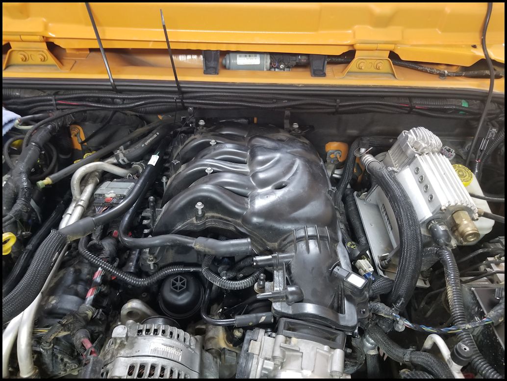
| 71. Reinstall the engine cover. |
|
|
| 72. Once I was done, I took the time to change out the engine oil and then I took it to the shop and had them do a coolant flush. I was due for both of those, so I just timed the oil cooler replacement knowing that I would have to do these anyways to be on the cautious side. |
| |
