Intro
How many times have you been on a trail and said “If I only had
a little more ground clearance I wouldn’t have gotten stuck,”
or been off camber with a tree or rock threatening to do bodily harm to
your Jeep. How about that Highway ride after you finally managed to get
the clearance that you needed. Remember that garage that you used to park
in occasionally to work on the Jeep that now the Jeep can’t get
into, and of course let us not forget the significant other that doesn’t
really enjoy climbing up into the Jeep.
How would you like to be able to change the height of your jeep, tilt
the jeep away from that obstacle, have 2 different heights 1 for off road,
1 for on road and have the ability to lower the jeep to a sensible level
for the significant other all at the push of a button? If your answer
is no, then don’t bother reading any further. If your still interested
then AiROCK™ by Off Road Only may be for you.
Discussion
AiROCK™ is a computer controlled air spring system that replaces
the coils in your Jeep. The air springs come in two sizes, a 4”
and a 6” size. The kits include 4 springs, 4 shocks, 4 height sensors,
AiROCK™ Control Unit (ACU), 1 dash mounted controller, a wiring
harness and air tubing. Since this is only a coil replacement system you
will still need the suspension system and air source (typically Onboard
Air) for the system.
AiROCK™ offers some distinct advantages over coil spring systems.
The biggest advantage is that the user controls the height, pitch and
roll of the vehicle with a just the touch of a button. Another great advantage
of air springs over coils is that the air springs do not rebound off of
an obstacle. This allows for a ride that is smooth over obstacles without
that sudden spring action that could throw your jeep past it’s center
of gravity and out of control. One other advantage is Air springs do not
sag over time. If you want 4” of height, you get it, even when you
add in extra weight, the system just puts more air in the bags to maintain
the height. You also gain the ability to change tire size and only have
to bump up the height on the springs. We have all rode in vehicles that
were really tall just to clear the tires underneath them off road. Well
with AiROCK™ you can do that and still maintain a lower ride height
on road.
The vehicles speed and the height of all for air springs are monitored
to allow for total control of your vehicle. AiROCK™ has 3 operating
modes. These are “Off-road”, “On-Road” and “Freeway”.
Off-road you have complete control of your height and vehicles angle.
You can control the center of gravity by lowering the vehicle, or raise
the vehicle to clear an obstacle. You can rock the vehicle to the side
to avoid that tree or rock on the side of the trail that is always catching
your windshield frame or body part. You can even raise or lower the front
and rear ends to allow for you to get up or down that obstacle. Most importantly
you have some control of your center of gravity.
On-road the system maintains your stability by automatically compensating
for body roll and pitch. An example would be during a panic stop the sensors
would automatically note the sudden down force on the front springs and
pressurize to stop the front from nose diving.
Freeway the vehicle automatically lowers itself for a more stable ride.
The system will monitor the springs and assist with roll control by pressurizing
springs on either side of the vehicle depending on drivers reactions to
the road conditions.
One other advantage is an optional feature, when activated, that automatically
lowers the vehicle to the bump stops to facility getting in and out easier.
Some people are interested in how much flex will an AiROCK™ kit
achieve. The system will flex comparable to the coil suspensions. The older
kits did lack a little bit of flex, but with the new Walker Evans shocks
that issue has gone away. Off Road Only is constantly listening to the
owners of AiROCK™ and improving the system.
26-Apr-2018th this kit will bring a few things to light right
away. The first thing you will notice will be the air noise from the solenoids,
you will get used to it after a little while. Though I am assuming that
you can actually hear them over the tires. Once you start driving you
will notice the softness of the ride, almost like you are riding on air.
The biggest change you will notice comes when you drive fast enough for
the system to shift to freeway mode. The suspension will now react to
turns, stopping and even bumpy road surfaces.
Off-road is where the suspension really shines. Bumps are soaked up,
you don’t rebound off of obstacles. Those trees and rocks that you
used to have to avoid, now slide right by as you tilt the jeep away from
them. I was able to run the same trails with both springs and the AiROCK™
suspension. The AiROCK™ made the trail almost too comfortable to
drive. The most enjoyable comment came after the word about a low hanging
branch came over the radio. The ability to drive right up to the branch
and hit all down on the AiROCK™ so that I could drive under it received
the comment “Now that’s cheating.”
I would have to say the feature on AiROCK™ that allows for the
most fun with the kids and even some admiration from the local low-rider
club is the demo mode feature. The mode will put the AiROCK™ through
it’s range of motions and will gain a lot of attention.
I purchased my kit through Mac at www.macs4x4.com and Steve at Off Road
Only. Mac and Steve are awesome to do business with. The kit is a technical
installation and Off Road Only provides a nice installation manual. Manual
is available on the web site. I would not recommend installing this kit
unless you have at least a moderate skill in mechanical work. Incorrect
installation can be very expensive.
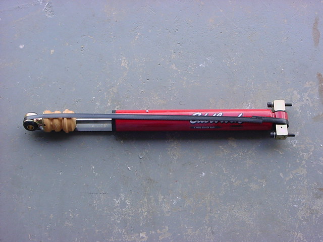
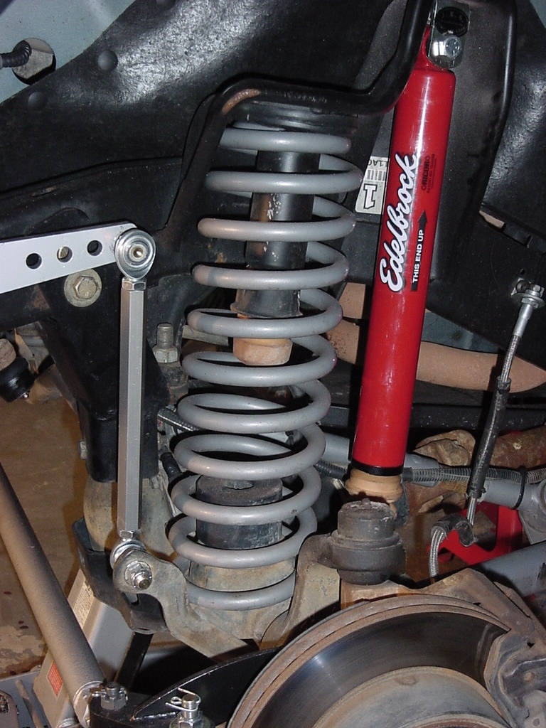
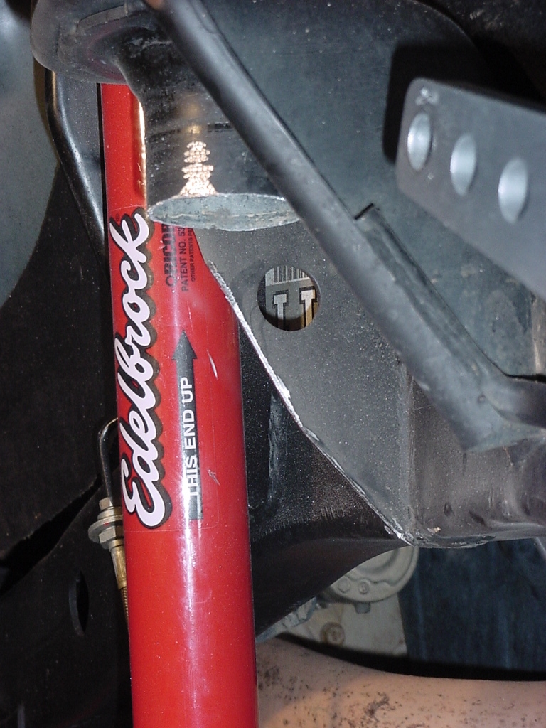
The installation if for a 6” AiROCK on a Rubicon Express Long
Arm Suspension. It shows the older Edlebrock Shocks vice the new Walker
Evan’s.
I had always been very interested in the ability to control
the aspects of a jeep from in the cab. The ability to tilt and lean,
correct when off camber, lift the jeep when you get high centered, or
lower it for better riding on the highway. So I decided to install
a 6" AiROCK suspension into the Jeep. This write up is currently
a rough draft but since a few people wanted to see it, I decided to put
it up a little early or in this case since I'm far behind on write ups,
a little late. This was actually installed last year in 2004.
Tools
Needed:
Hammer
Vise or C-clamp
Flat Tip Screwdriver
Phillips Screwdriver #2
19mm Deep Well Socket
3/4" Deep Well Socket
1/4" Socket
5/16" Socket
1/2" Socket
9/16" Socket
3/4" Socket
13mm Socket
15mm Socket
18mm Socket
Ratchet
Short Extension
Long Extensions (2)
3/8" Combo Wrench
1/2" Combo Wrench
9/16" Combo Wrench
11/16" Combo Wrench
3/4" Combo Wrench (2)
1 1/4" Combo Wrench
13mm Combo Wrench
15mm Combo Wrench
18mm Combo Wrench
5/32" Allen Wrench
Drill
3/8" Drill Bit
1/2" Drill Bit
7/8" Drill Bit or Dremel
Small Adjustable Wrench
Large (12") Adjustable Wrench (2)
Ruler
(4) 6 or 12 ton Jack Stands"
Floor jack
This lift kit will require you to support the entire Jeep
by the frame during install. Due to the air springs requiring pressurization
prior to the axles supporting the vehicles weight. The shocks will
withstand the weight of the Jeep for a short period of time. I recommend
jacking and supporting the front end first then lifting the rear and dropping
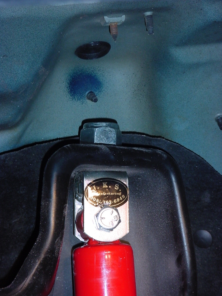
the vehicle in the reverse order.
Installation:JKS Bar Pin Eliminators and Shock Adaptors to Shocks
I
assembled all the parts required to assemble the shocks. The
on thing I noticed was how massive the Front Upper Shock Adaptors
were.
Shocks
Front Lower Bar Pin Eliminators
Rear Upper Bar Pin Eliminators
Front Upper Shock Adaptors
Rear
Upper Bar Pin Eliminators
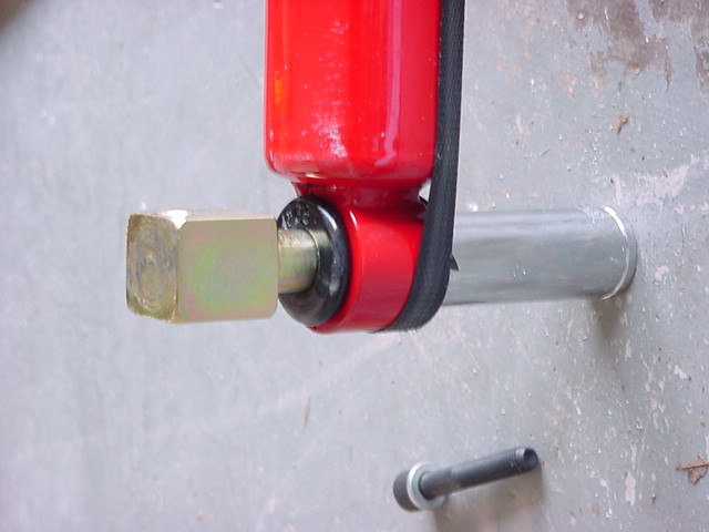
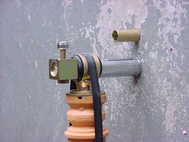
1.
Install the Rear Upper Bar Pin Eliminators. You will first
need to drive out the sleeves from the bushings. I used the
bar pins themselves to do this. Place a 19mm or 3/4"
Deep Well Socket underneath and tap the Bar pin though the shock
eye.
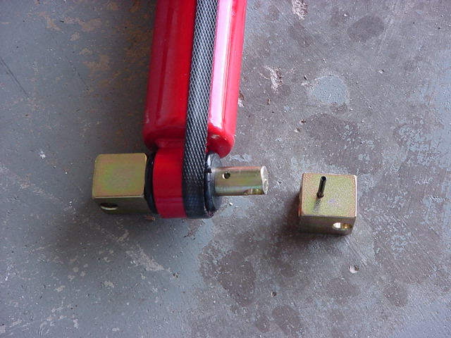
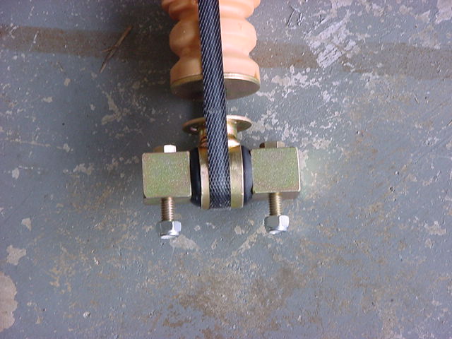
2.
Once you have the pin all the way through you need to install the
other side. There is a small pin that needs to go through
the pin to hold the block in place. I used a c-clamp to push
the block all the way in and lined up the holes in the block and
pin. Then gently tap the pin into place. You can also
place a bolt through the block and pin to help hold it on while
installing the pin.
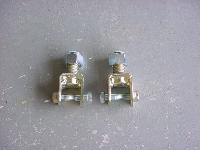
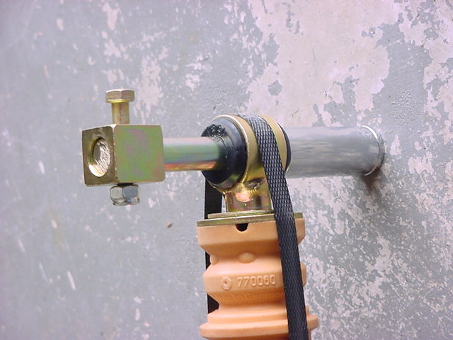
3.
Fully installed on the Rear Shocks.
Front
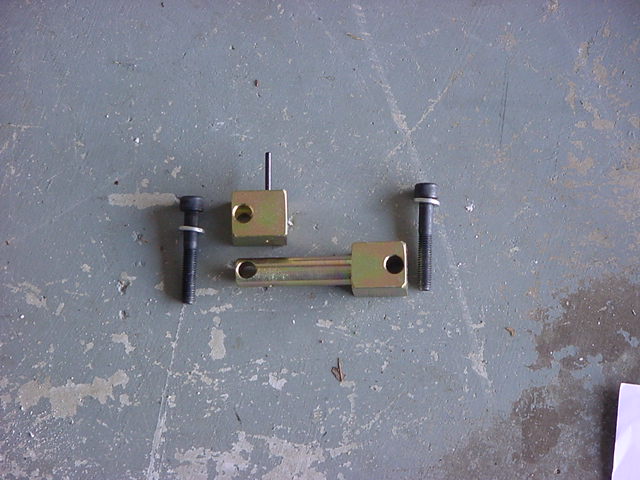
Lower Bar Pin Eliminators
1.
First remove 1 nut and bolt from one side and remove the block from
the bar pin eliminator.
2.
You will need to drive out the sleeves from the bushings.
I used the bar pins themselves to do this. Place a 19mm or
3/4" Deep Well Socket underneath and tap the Bar pin though
the shock eye.
3.
Once you have the pin all the way through you need to install the
other side. I used a c-clamp to push the block all the way
in and lined up the holes in the block. Then place a bolt
through the block to hold it in place.
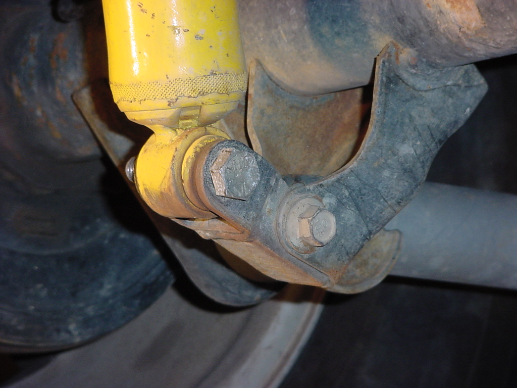
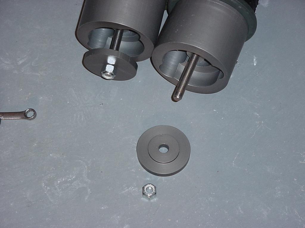
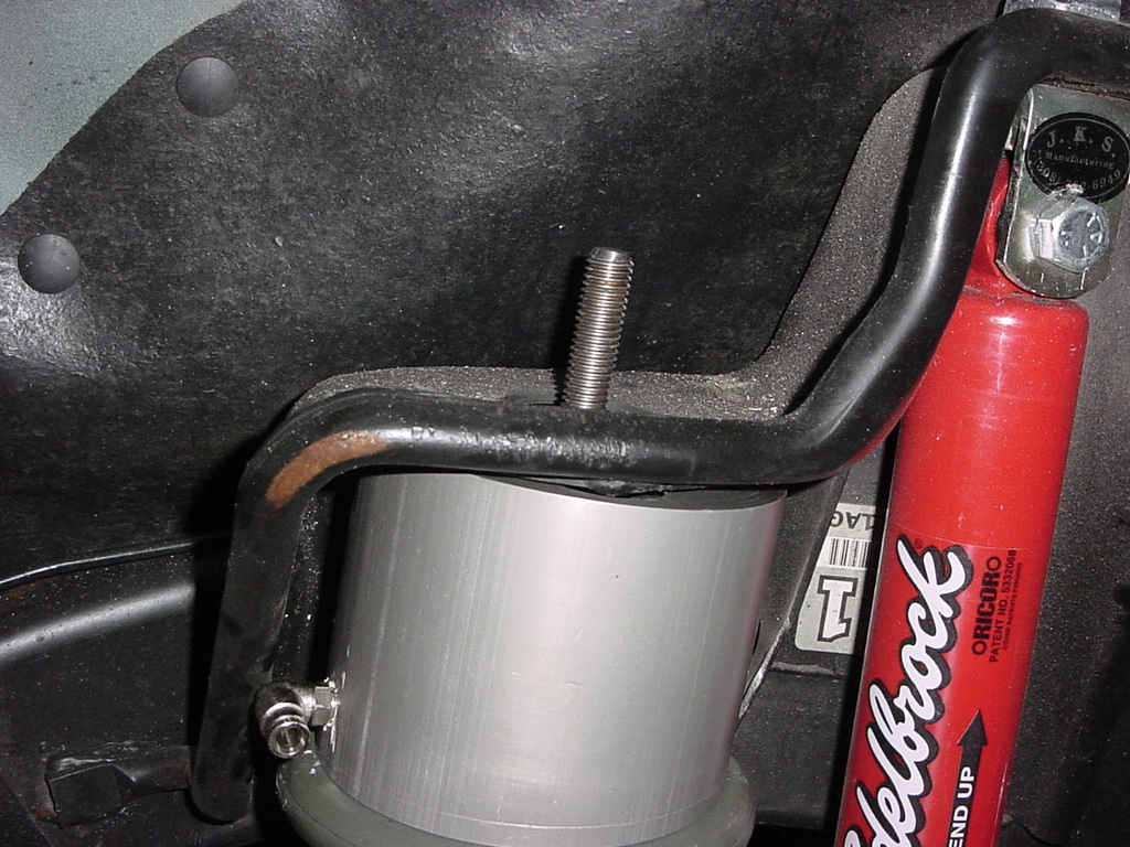
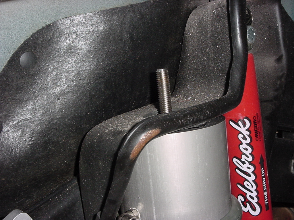
Shock
Adaptors
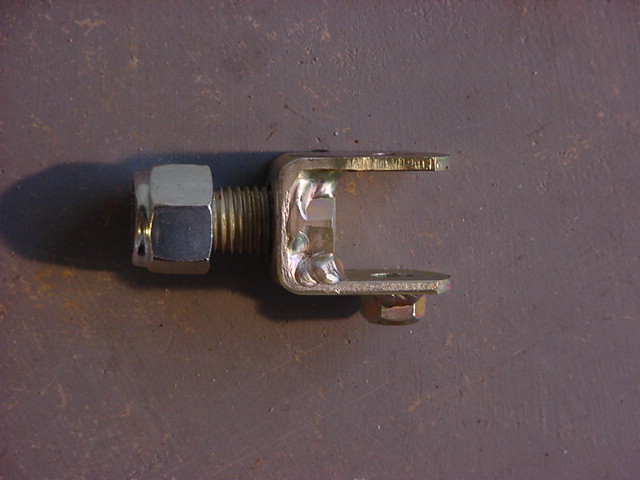
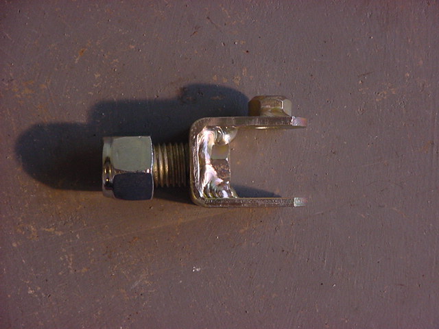
1.
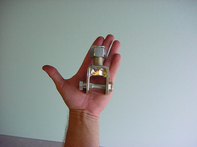
Check your shock adaptors. The center bolt is welded in and
in my case the welds interfered with the upper shock eye on the
shocks. The shock eye sits very close to the top of the bolt
in the adaptor and as you can see from the pics the welds are over
the top of the bolt. I ground down the welds flush with the
top of the bolt.
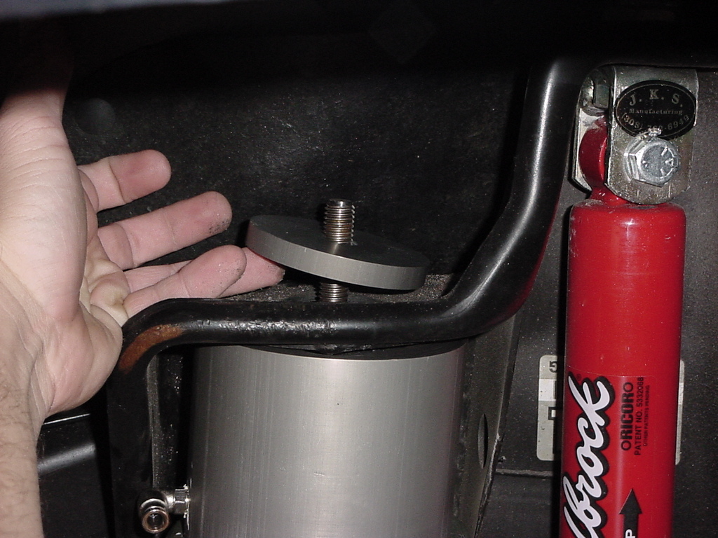
2.
Slide the adaptor over the shock bushing and tap down with a hammer
if required. Once you have the bolt hole lined up insert the
bolt through the shock eye and tighten using a 3/4" Socket
and 3/4" Combo Wrench. Make certain that the shock adaptor
is inline with the shock body.
3.
Here is the assembled front shock.
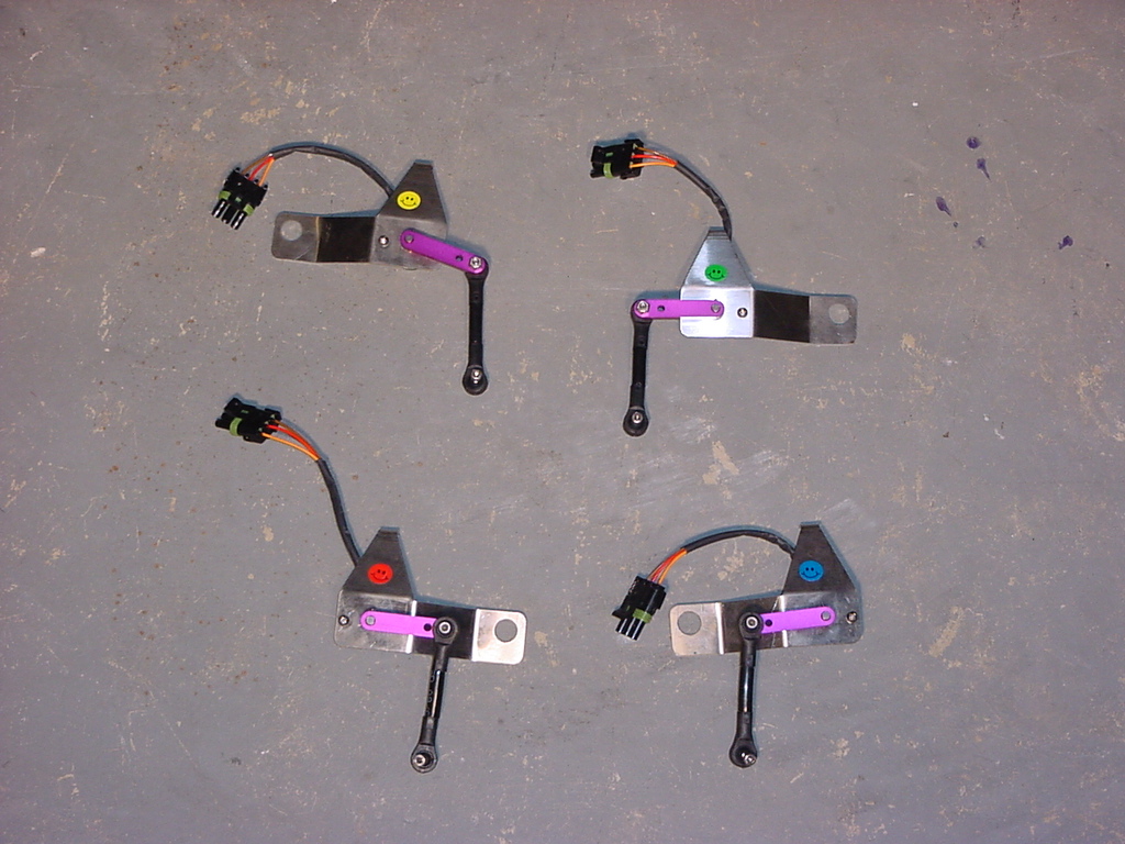
AiROCK
Height Sensors
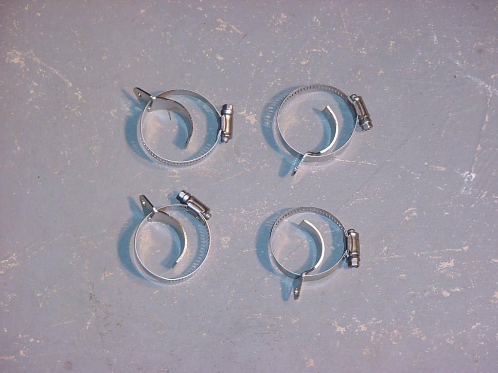
1.
Unpack the four height sensors and the 4 clamps for the arms.
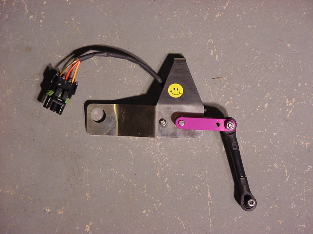
2. The height sensors will have
a colored sticker on them. These stickers designate the
position of the height sensor on the Jeep. The wire on the
B terminal of the 3 plug connector should match the color of the
sticker.
Left Front - Yellow (I)
Right Front - Green (II)
Left Rear - Red (III)
Right Rear - Blue (IV)
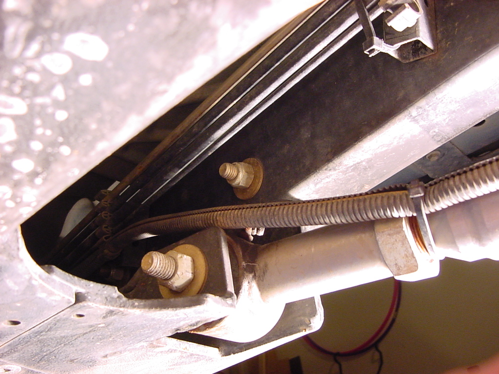
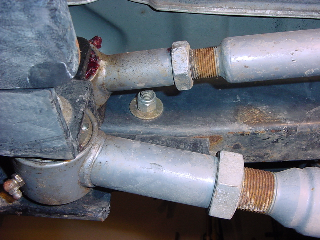
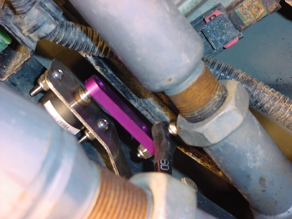
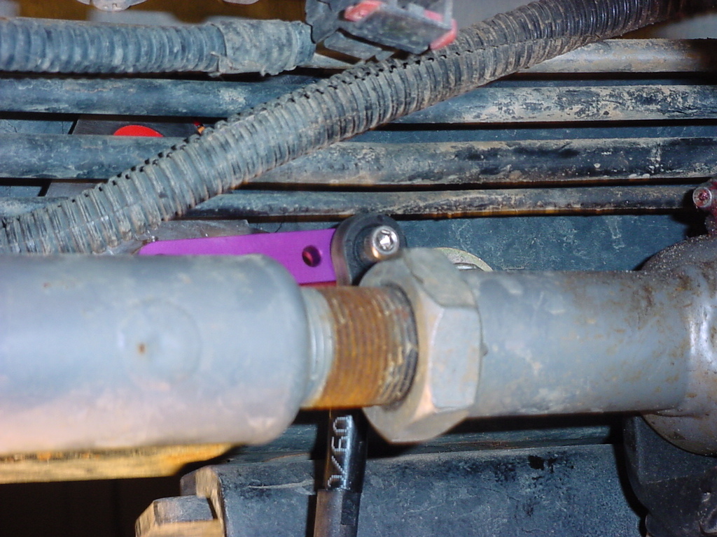
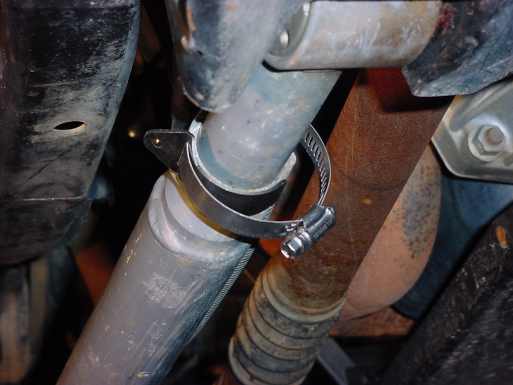
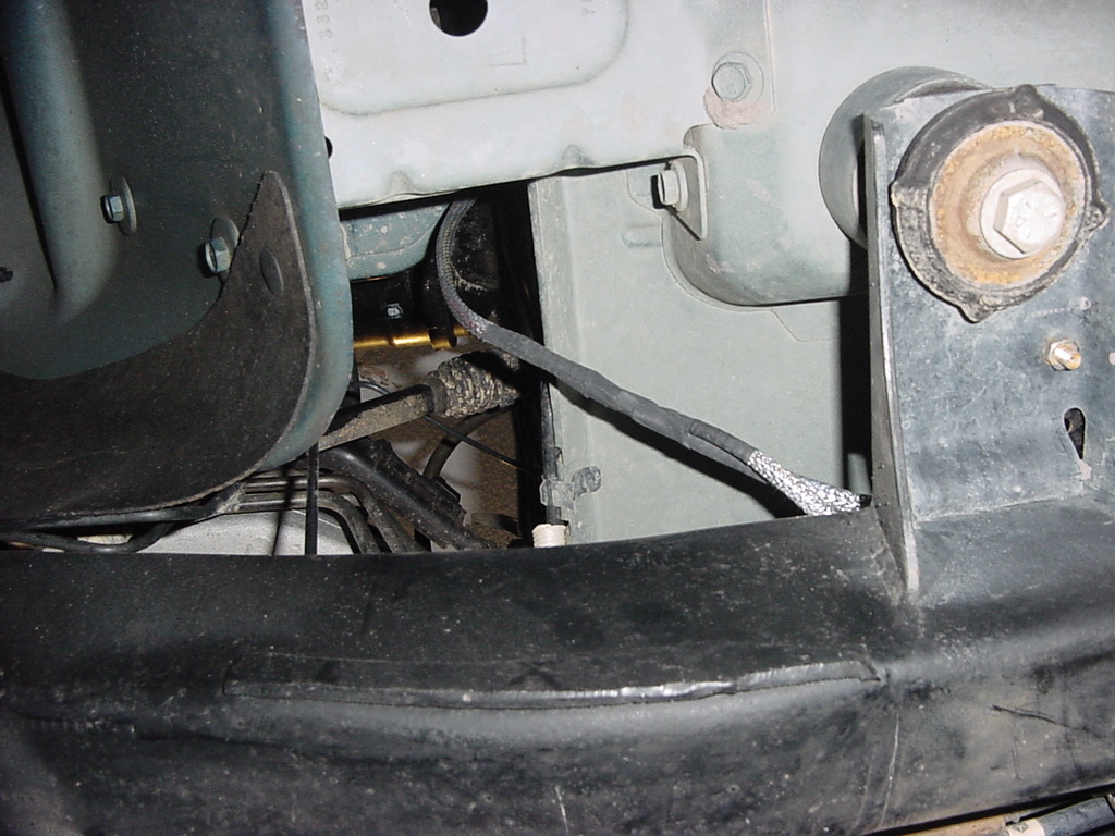
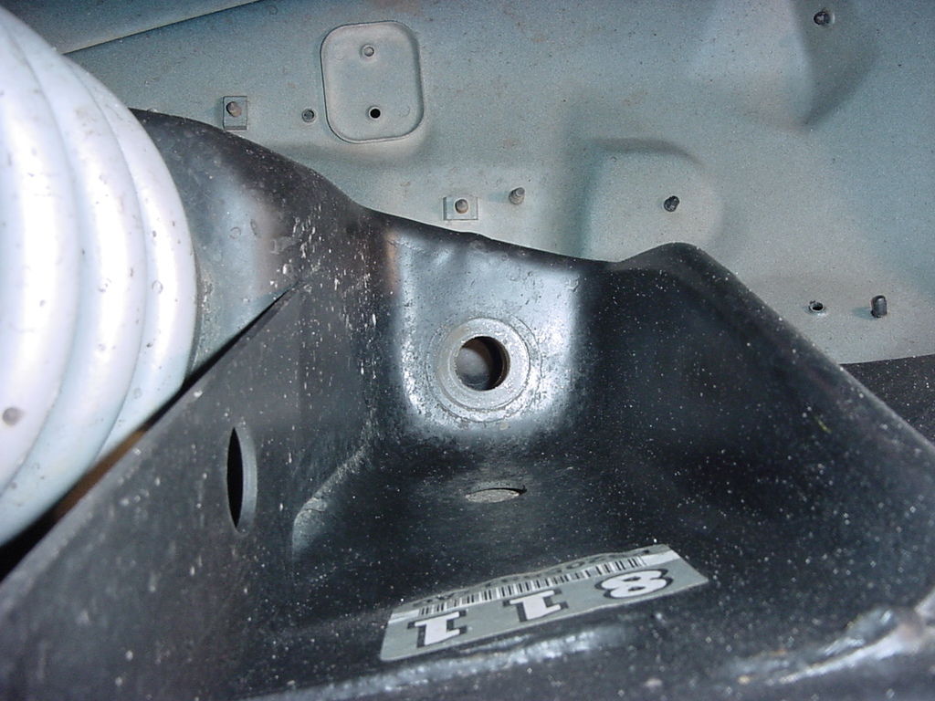
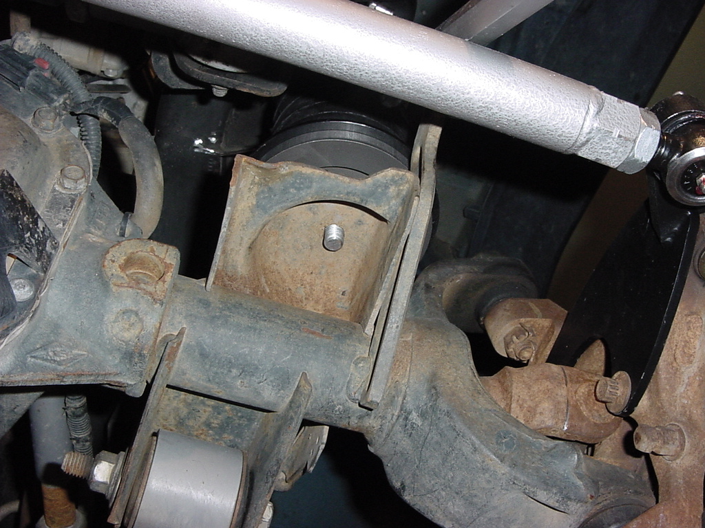
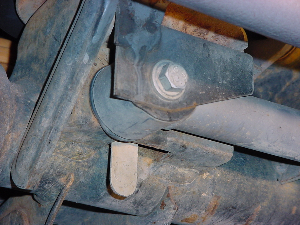
3.
The Height sensors for the Rubicon Express Long Arm TJ suspension
systems have been designed to utilize the outer two bolts that hold
the outer frame rail brace to the frame. The bolts run through
the frame horizontal to the ground. These bolts should have
been installed so that the nuts are on the inside of the frame,
if not you will need to remove the bolt and install it properly.
Use a 3/4" Socket and Combo Wrench to remove and tighten these
nuts.
4. Remove the nut from
the bolt and install the AiROCK sensor bracket for that position.
The bracket should rest on the top edge of the frame rail to help
position it and prevent it from moving.
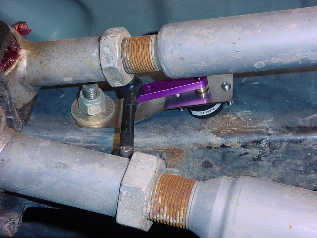
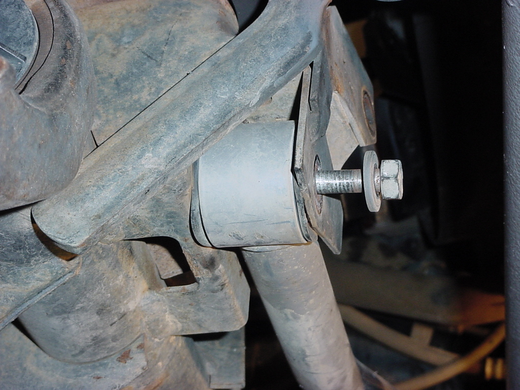
Note: The front and rear arms will have the sensor arm (Purple
anodized parts) pointed towards the front of the vehicle.
The front arms are the top 2.
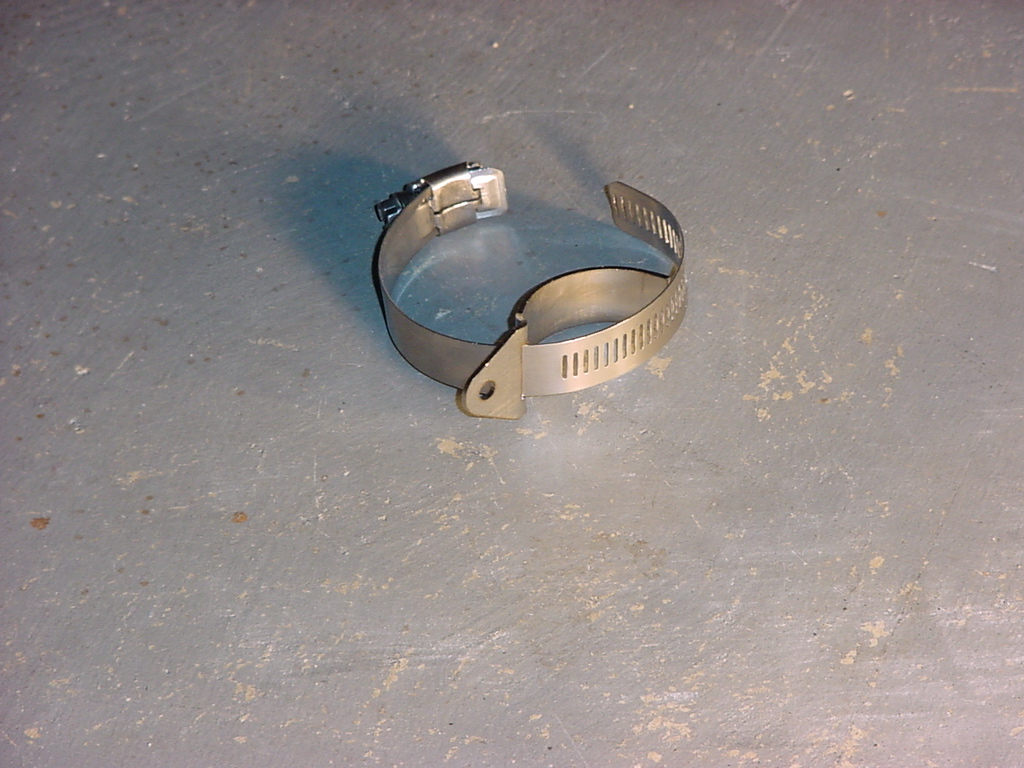
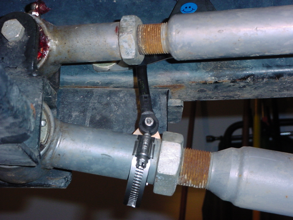
5.
Open up the 4 sensor linkage mounts with a flat tip screwdriver
(otherwise know as a hose clamp)
6.
Place the stainless link bracket over the lower control arm and
clamp to the control arm. I found that placing the bracket
on the outside of the front control arms and on the inside of the
rear control arms aligned the sensor arms to the best position.
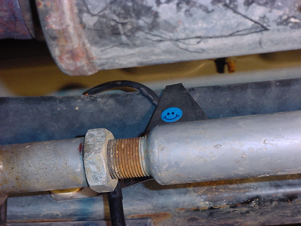
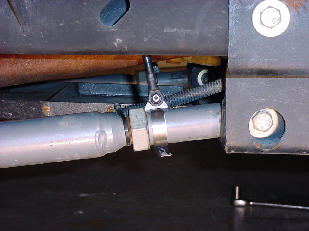
7.
Adjust the bracket so that it is sitting against the Jam nut on
the control arm.
8.
Rotate the bracket so that it aligns with the sensor arm. Ensure
that the sensor arm is free from binding and able to move freely.
Tighten the control arm bracket using either a straight tipped screwdriver
or a 5/16" socket and short extension.
9. Tighten
the bolt attaching the sensor arm to the control arm bracket using
a 5/32" Allen wrench and a 3/8" Combo Wrench. Install
the bolts so that the nut is on the bracket side.
AiROCK
Wiring Harness
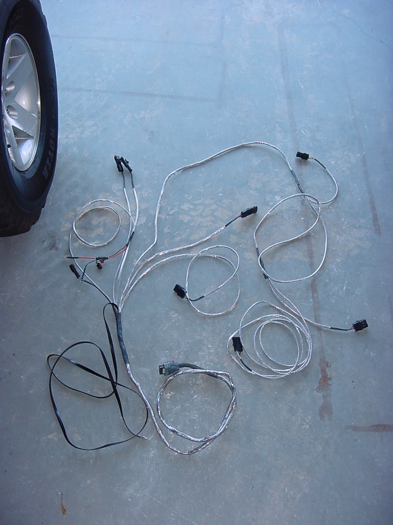
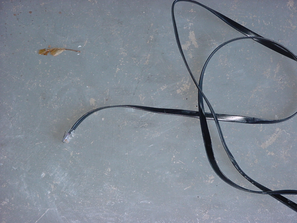
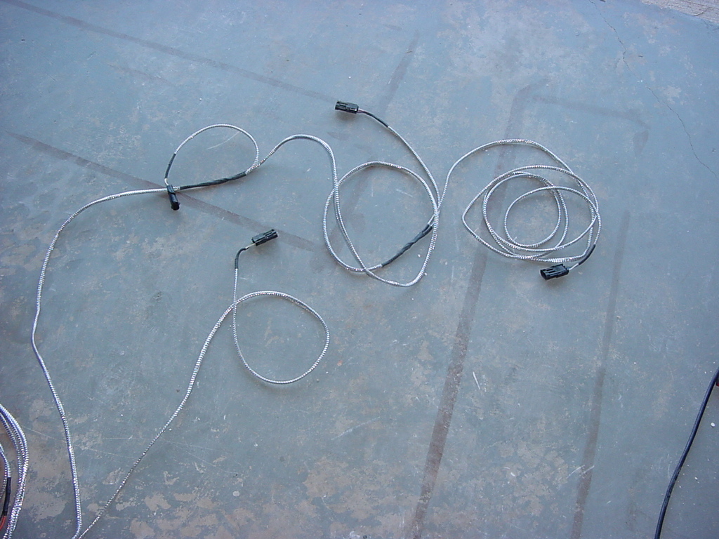
1.
Lay out the wiring harness and double check all the wires to make
certain that none of them have been damaged in transit. The
cables are nicely wrapped, but it's always good to double check
before you install this harness.
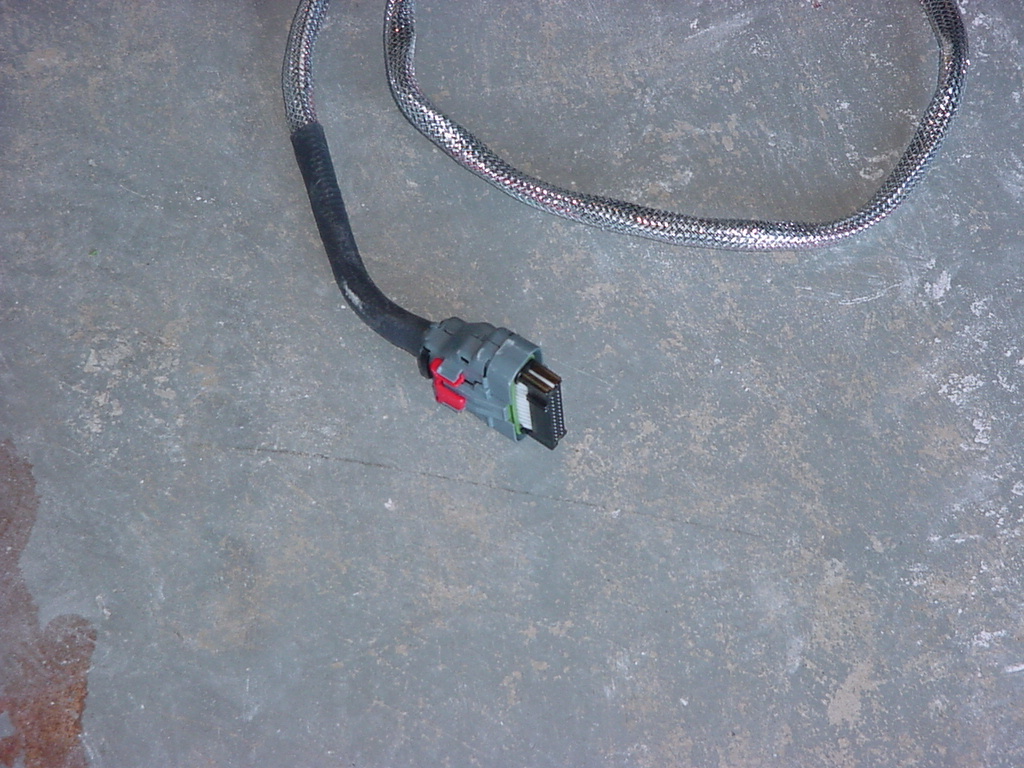
Controller
12 volt Connection
Speed Harness Connector
ACU Connector
Aux Input and Data Connectors
Height Sensors: H2 is the one with it's own cable, the other
is H1, H3, H4 (last one on the cable run)
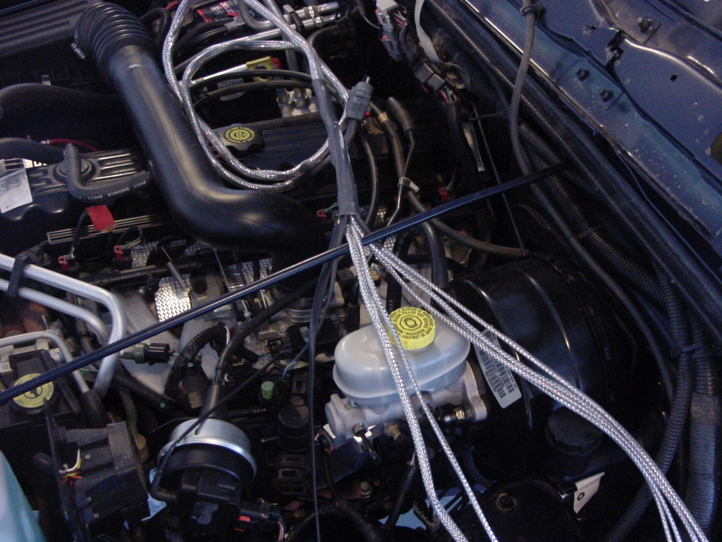
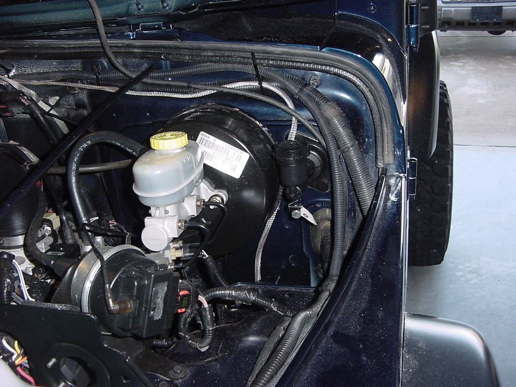
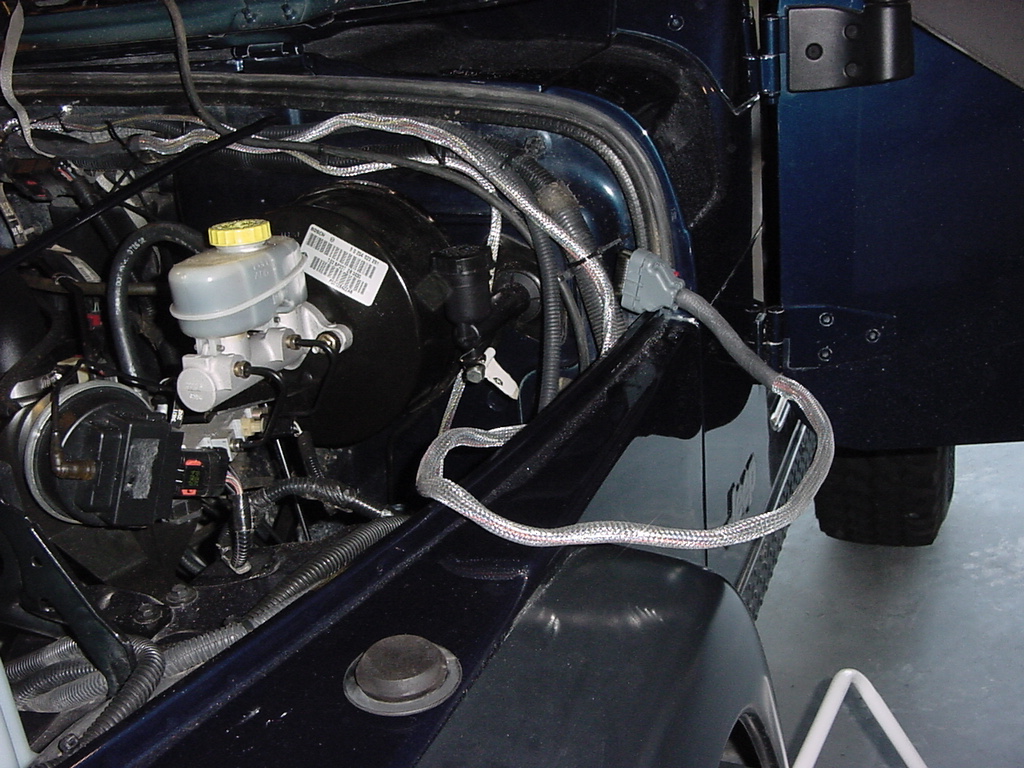
2.
The harness is designed for a certain layout on the Jeep.
The main Junction point (center of picture, wrapped) should be positioned
at the top center of the firewall, under the hood (most Jeeps have
a mounting tang at this point). Position the harness behind
it so that it will remain in place.
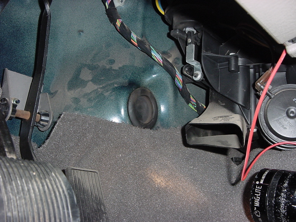
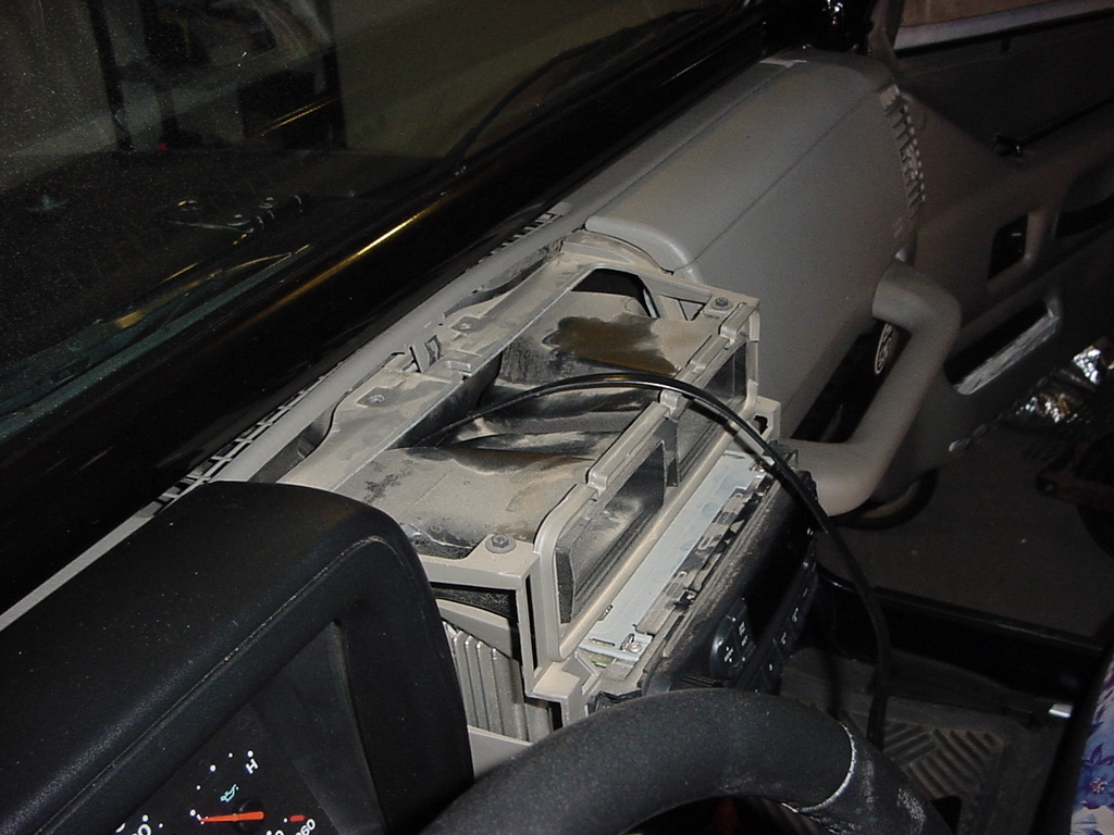
3. The
Controller cable will be run through the firewall. You will
find a plug at the bottom of the firewall that comes through behind
the console. Pull this out.
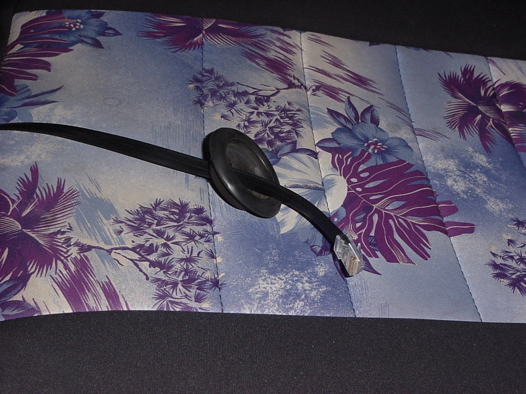
4. Cut
a slit through the plug and feed the controller cable through it.
I left it free until I was ready to route the cable through the dash
to the controller location.
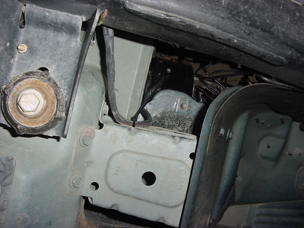
5. Route
the H1, H3, H4 cable over to the driver side. This cable
will run down along the driver side frame rail and loop to the passenger
side on top of the gas tank cross member. I routed it as far
over to the side of the engine compartment that I could. You
want to keep these wires away from the heat of the Catalytic Converters
that are on that side.
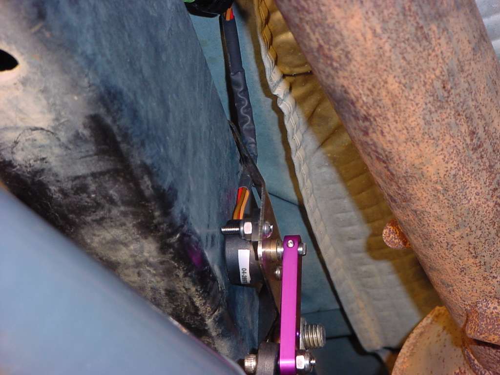
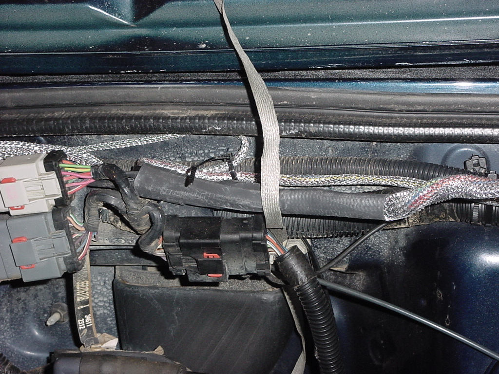
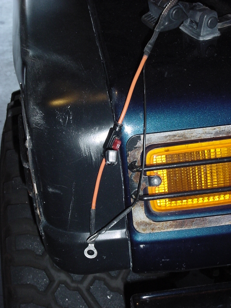
5a. Coming
down the Driver side. Connect the H1 sensor. I went right
down past the side of the box that connects the fender to the firewall.
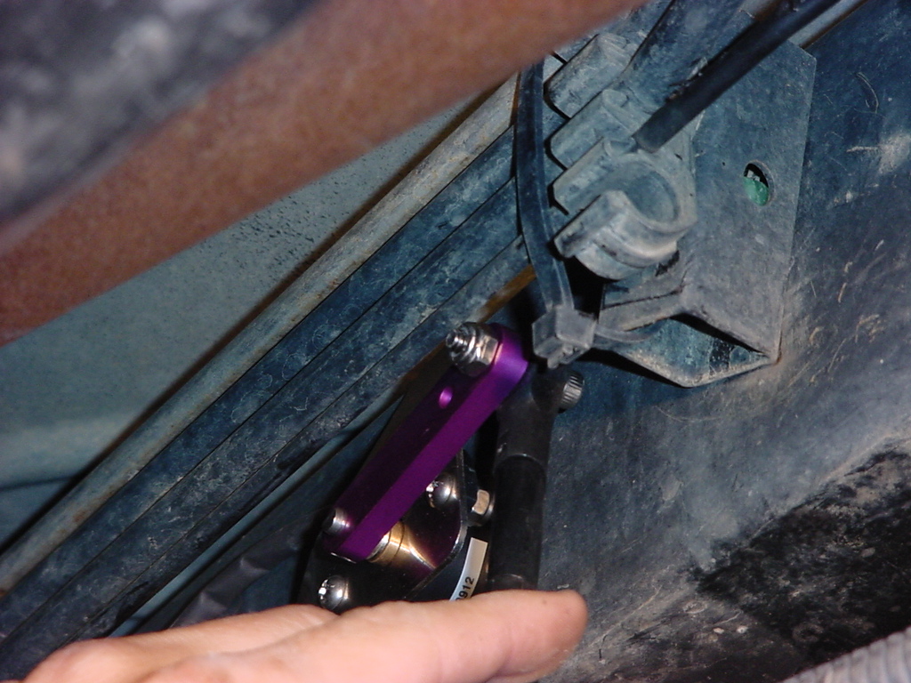
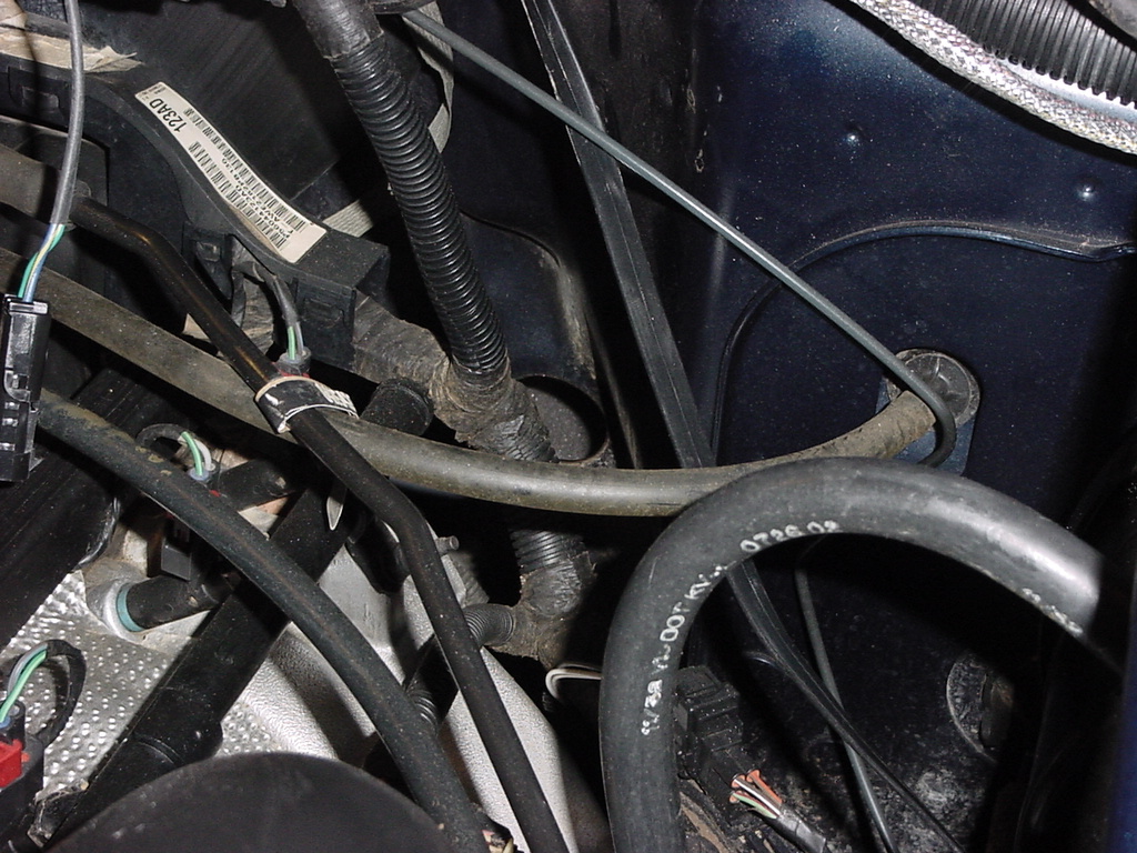
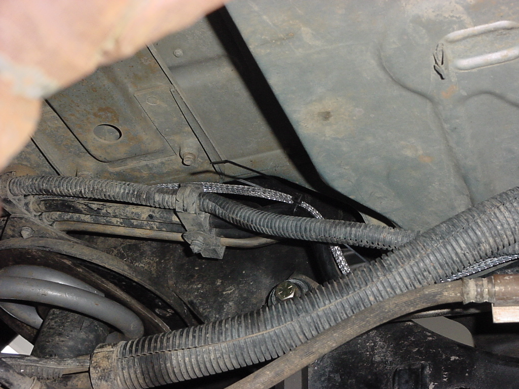
5b. Looping over the
gas tank cross member. Connect the H3 sensor.
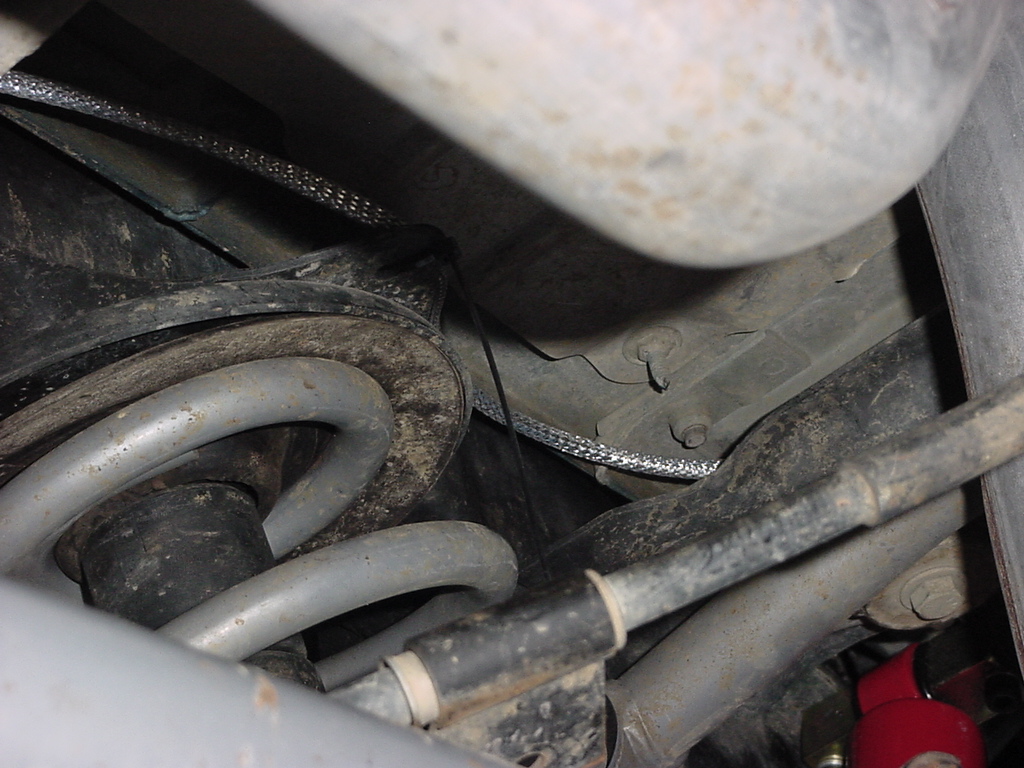
5c. Connected.
This is the H4 Sensor. I zip tied the cable to the sensor.
I am trying to find some small cable holders that will stick to the
height sensor bracket so that I can hold the wire better.
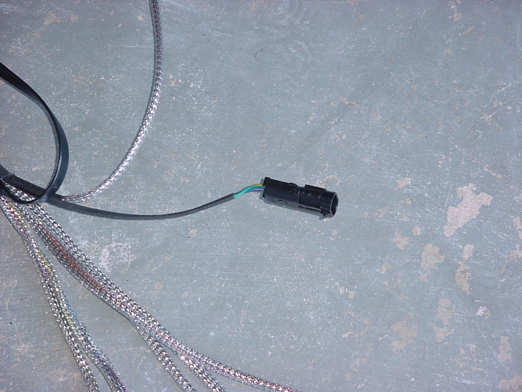
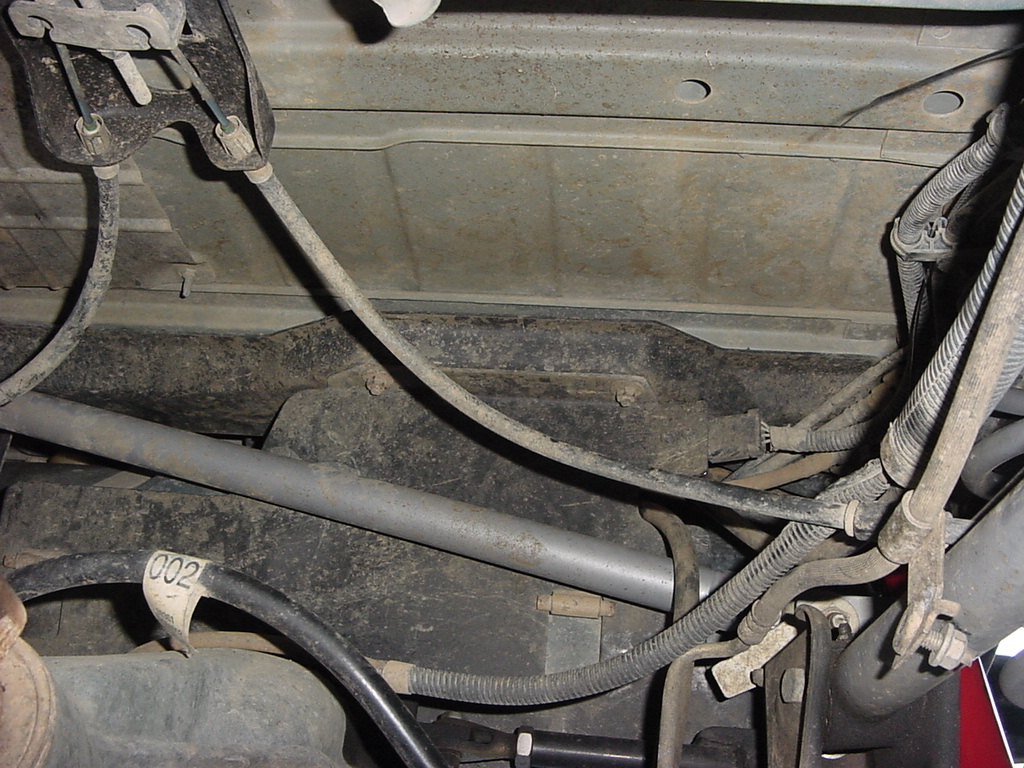
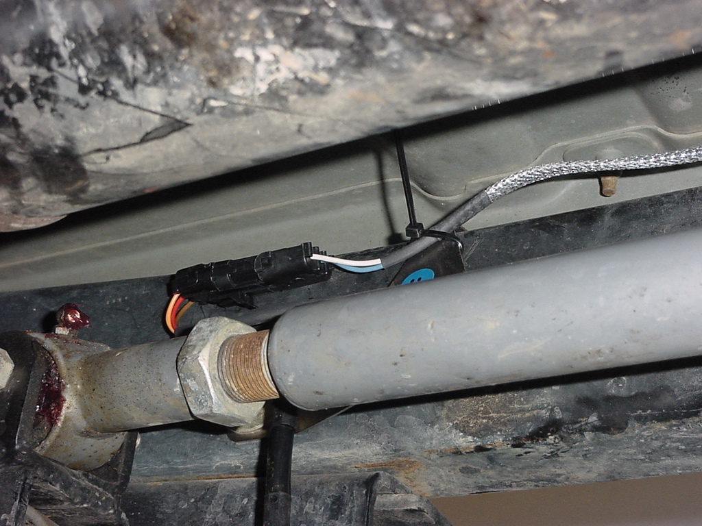
6. Now
route the single H2 height sensor lead over to the Passenger side
and down to the Right Front (Green II) Height Sensor.
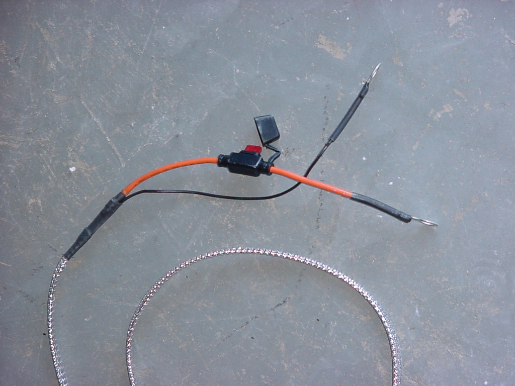
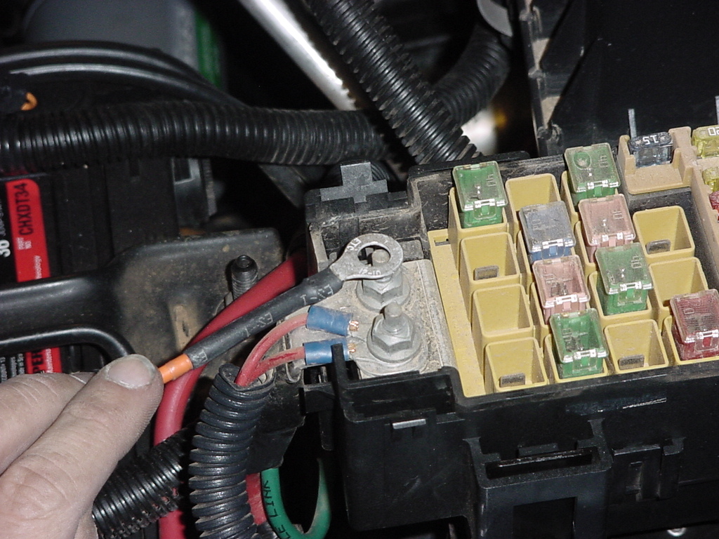
7.
Route the 12volt Connection over to the battery. Remove the
fuse and store it in a safe location. I decided to take a
tap straight off of the power distribution box. I used a 10mm
socket to remove one of the bolts and attach the positive (red)
cable to the box. I then attached the negative (black) cable
to the battery negative terminal.
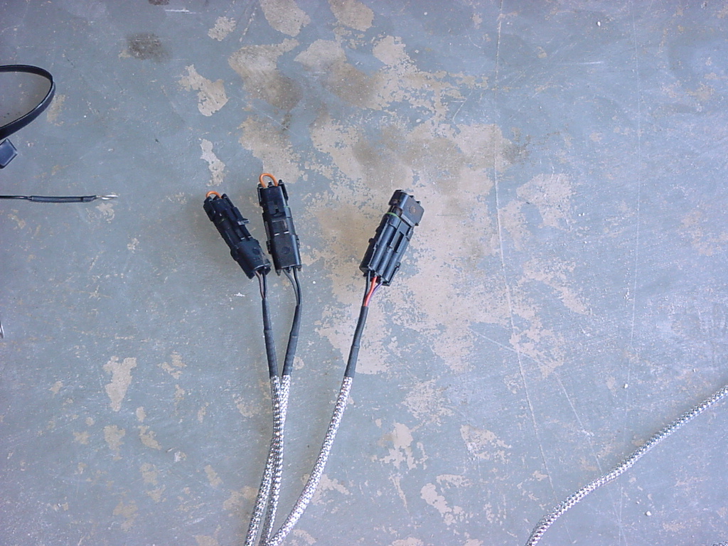
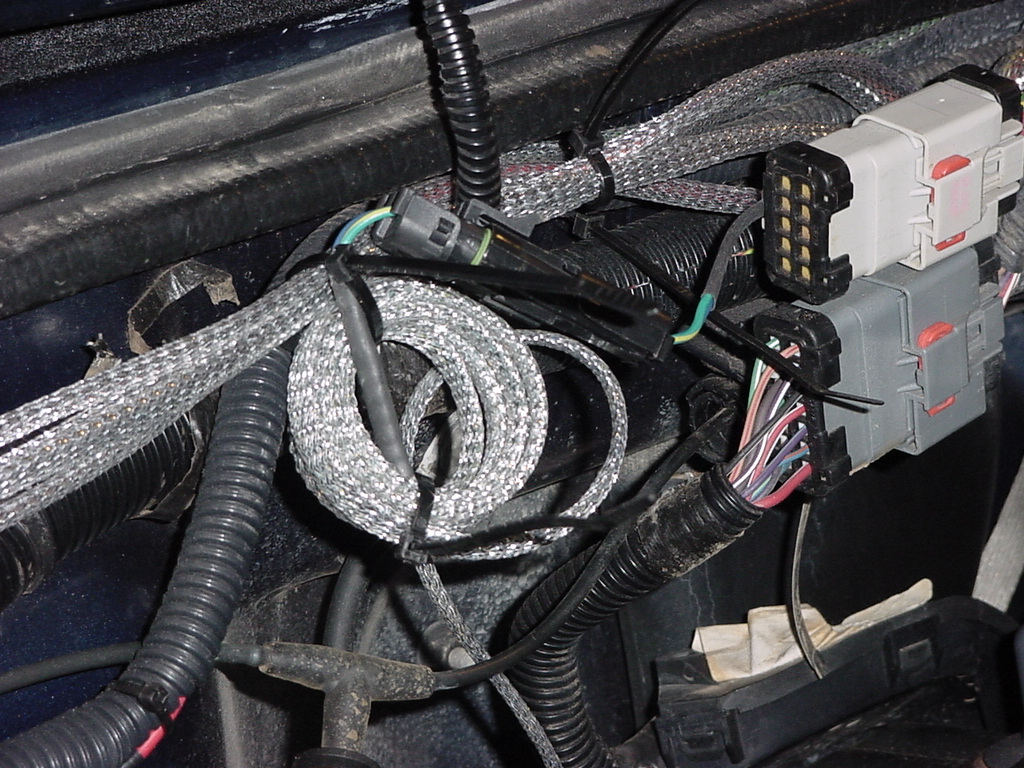
8. I decided
to zip tie the (2) Aux Input connectors and the (1) Aux Data Connector
together and leave them over by the vehicle computer.
9. Now
route the ACU cable over to the driver side and see how much room
you have to locate your ACU in. There is plenty of cable to
reach almost every place on that side that you can use. I did
check the fit of the cable into the ACU. Note: Placing the ACU
on your unprotected fender does lead to scratch's.
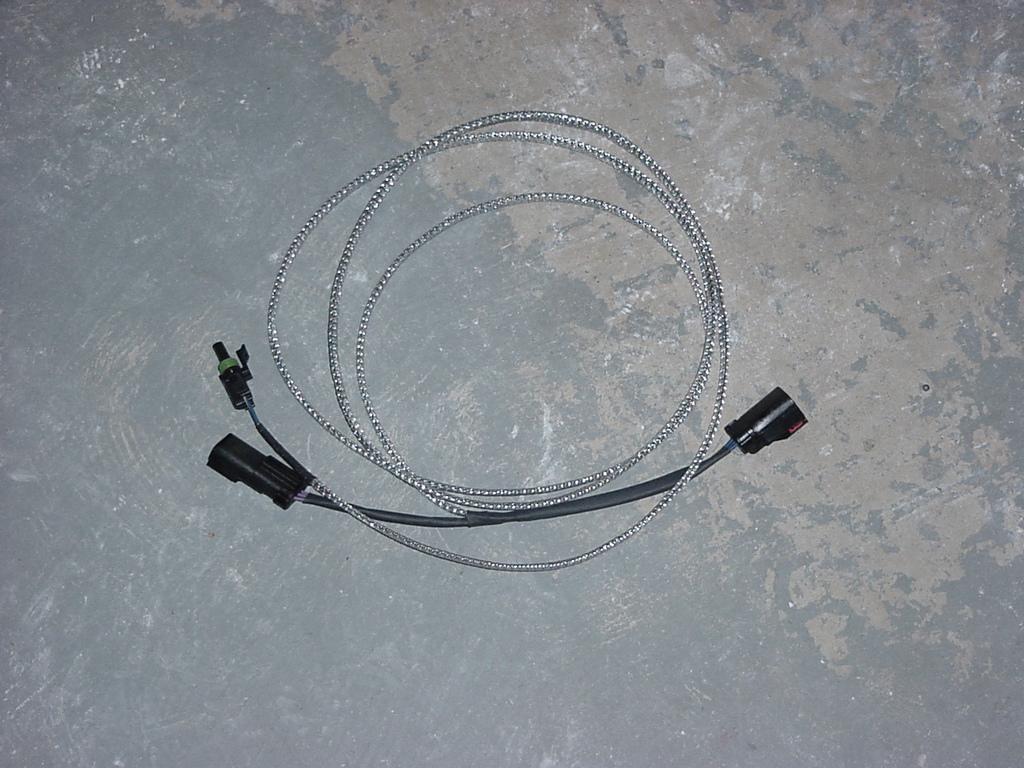
Speed
Harness
1. Lay
out the wiring harness and double check all the wires to make certain
that none of them have been damaged in transit. The cables are
nicely wrapped, but it's always good to double check before you install
this harness.
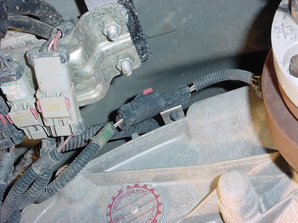
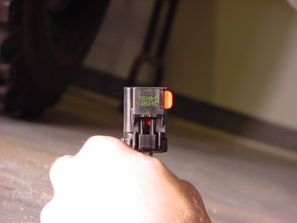
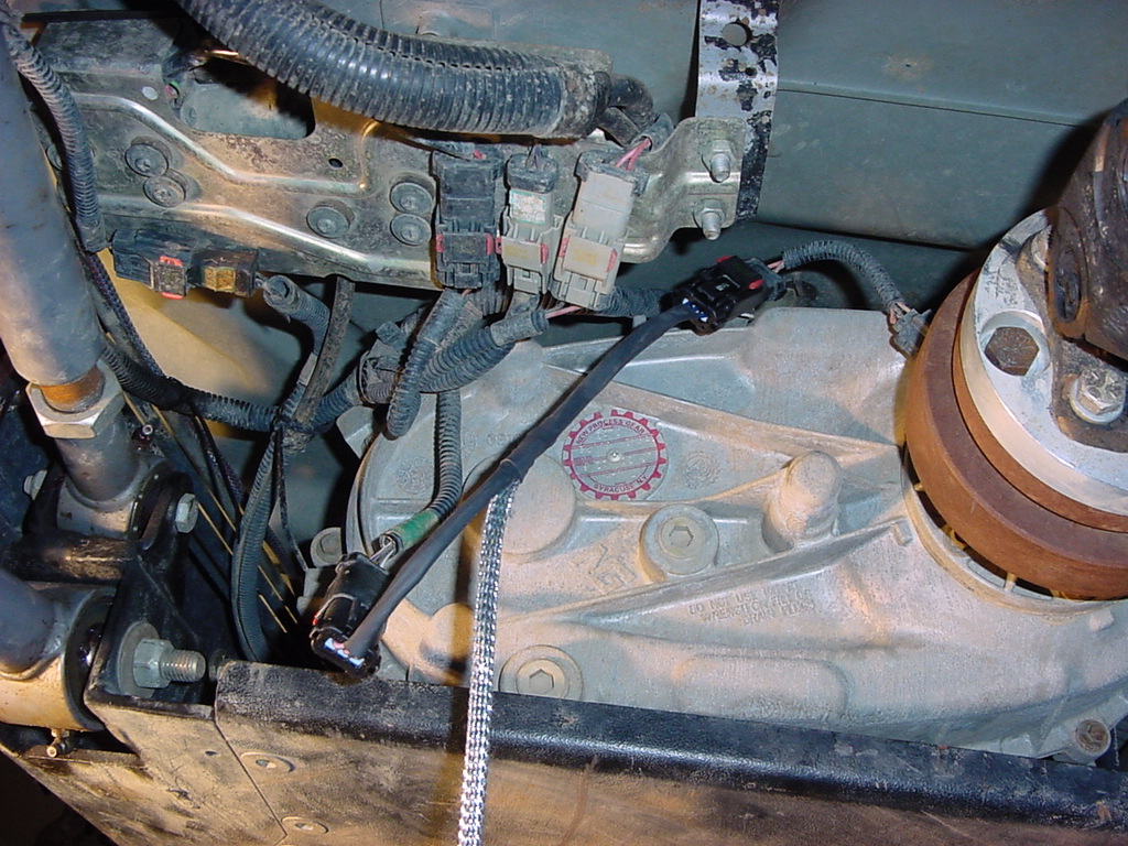
2. Locate
the speed sensor connector on top of the transfer case. One
side goes to the speed sensor located in the tail shaft section of
the transfer case. Pull the red lock button over to the side
and then unclip the connector.
3. Install
the Speed Harness between the connectors and zip tie up in place.
Now route the harness along the transfer case and transmission, then
up along the firewall.
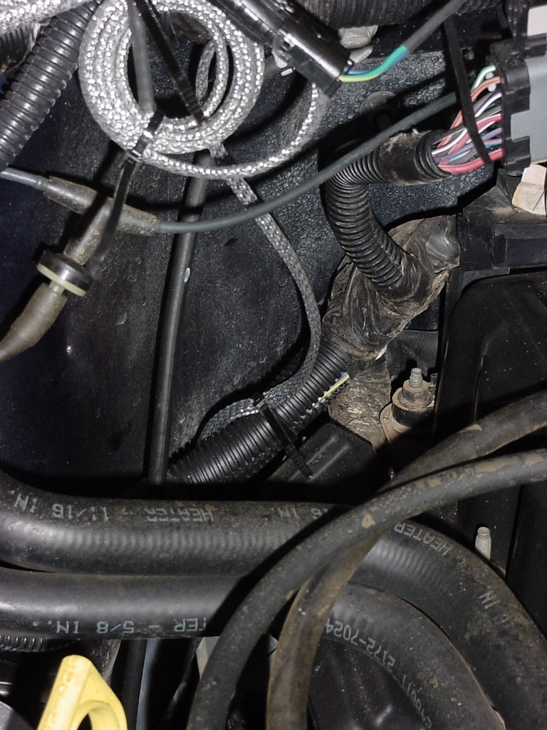
4. I did
have plenty of cable left over, so I could have probably routed it
along the frame rail, but decided not to undo it all so that I could
see if I did. I just coiled up the excess cable and zip tied
it in place. Now connect that other end of the harness into
the Speed Harness connector on the Main cable
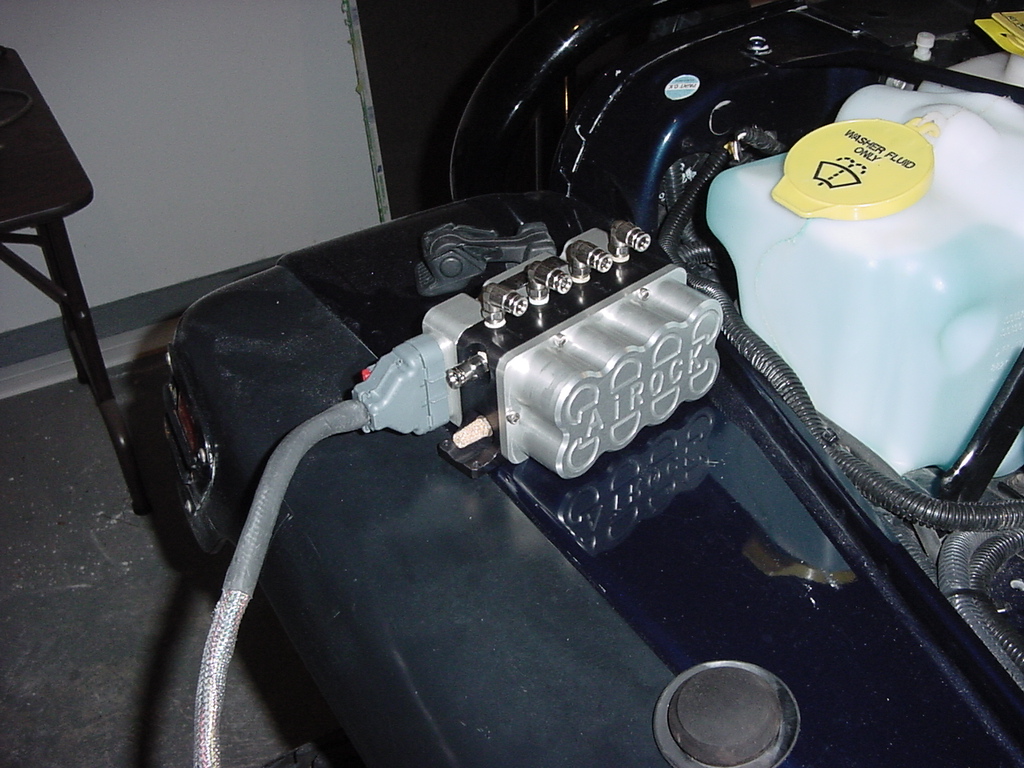
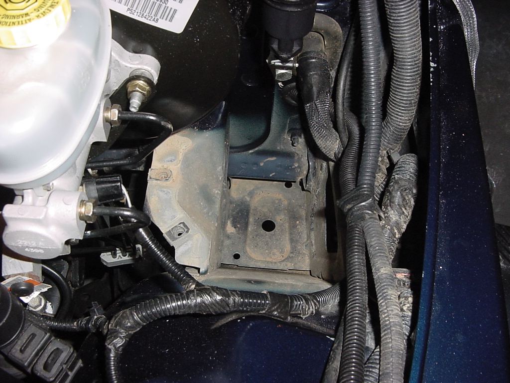
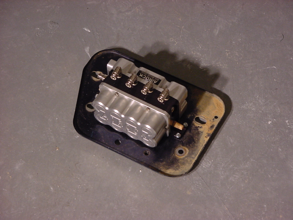
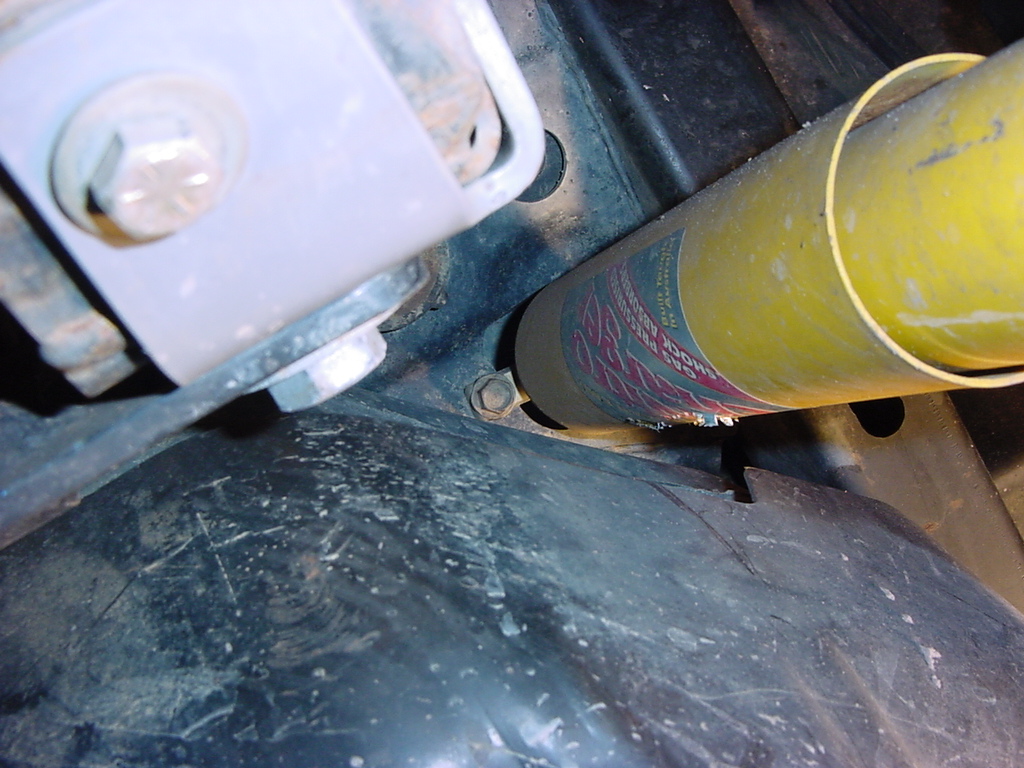
Mounting
the ACU
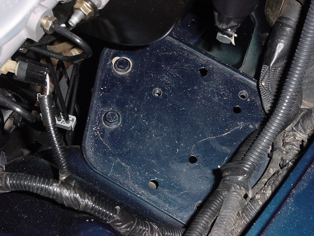
1.
I needed a convienent spot to mount the ACU out of the way.
Now since I had taken up most of the space on the fender I couldn't
mount it there, but nothing resided in the ABS tray on the driver side
so coincidently that became the home of the ACU.
2.
Remove the 4 bolts holding the tray in place with a 13mm Socket,
a long extension, and a 13mm combo wrench.
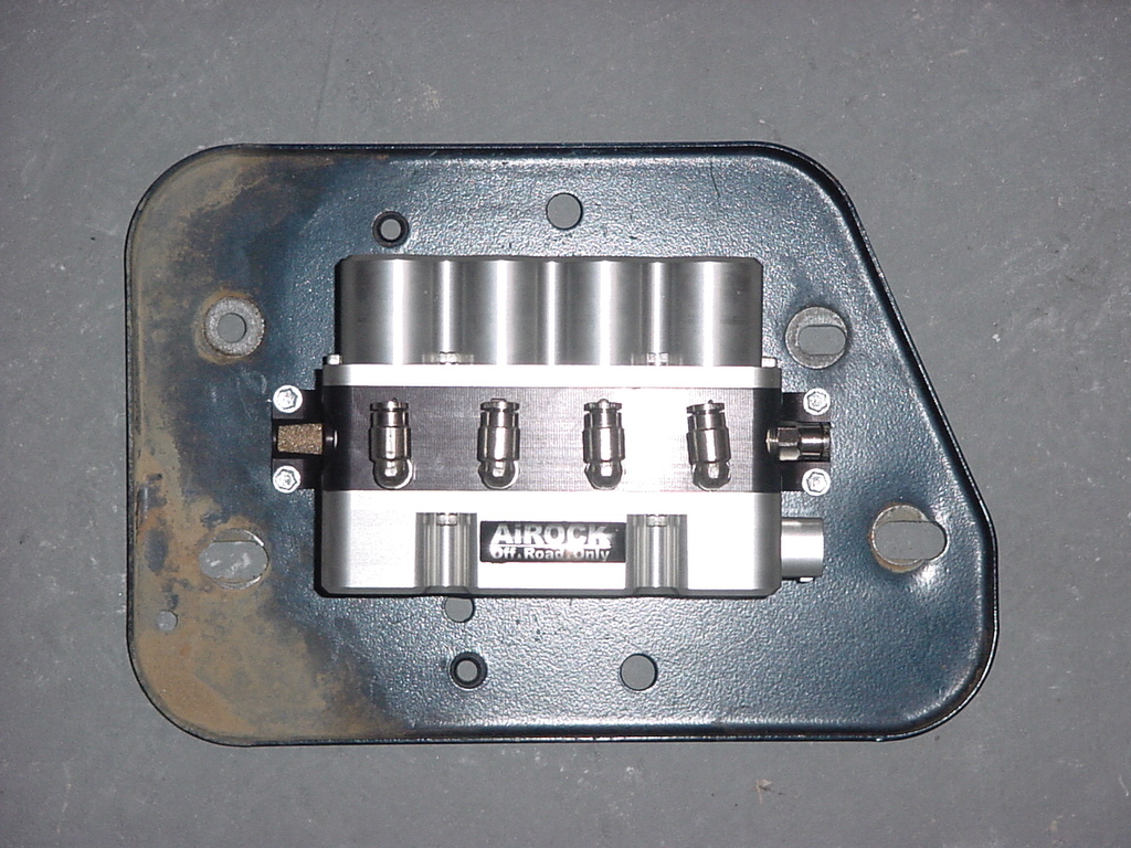
3.
I positioned the ACU in the center of the skid and installed the
screws. They are self tapers so all you need to do is drill
them down with a 1/4" socket. I used a ruler to line
up the ACU.
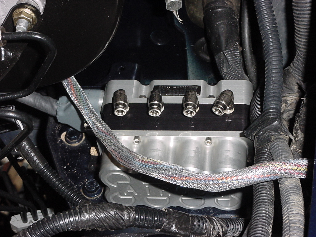
4.
Now reinstall the tray into the Jeep.
AiROCK
Controller
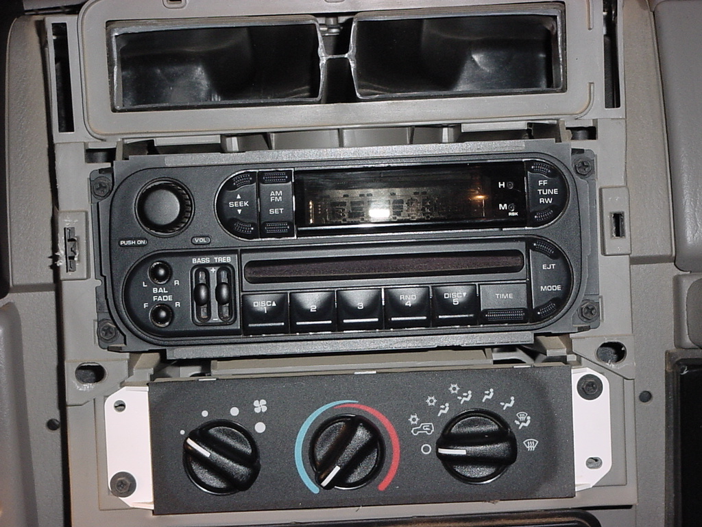
1.
Remove the center dash surround by first lifting the defroster cover
and removing the 2 phillips head screws that hold the surround in
place, then just pull the surround away from the dash.
2.
You will need to feed the control cable up behind the Heater/AC
controls and the Radio. This is not an easy task. If
you need additional room you can remove the radio and the Heater/AC
control panel. Note: The radio has a nut on the backside that
needs to be removed to pull it out.
3.
Pull the cable up the backside and out. I pulled all the access
cable in from the engine compartment. Remember you have the
exhaust on the other side so to much slack in the cable could cause
it to touch or get close enough to the exhaust to melt the cable.
I just tucked the unneeded cable down behind the dash.
4.
Now reassemble the dash.
5.
I did not mount the controller until I was able to test the system
out and verify operation. The double sided tape that holds
the controller to the dash is very hard to remove, so if for some
reason your controller is bad you will have a pain getting it back
off. Note: I did have a controller that the controls had accidentally
been reversed left to right on it but I knew about this before the
install, and had a corrected one before I was even ready to put
it on the street.
6.
Once the system is tested remove the double sided tape from the
bottom of the controller and position on top of the center dash
surround.
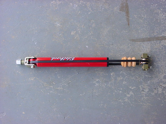
Shock
Installation
Edlebrock
Shocks
Actual
Length
with parts
Front
Rear
Front
Rear
Extended
26 5/8"
26 5/8"
28 3/4"
27 1/8"
Compressed
19 1/2"
19 1/2"
21 5/8"
20"
I
was playing around and wondering how much of a lift the edlebrock's
would give to the RE 4.5 Coils. Didn't end up being much,
but it was about 1/2". So I installed the shocks before
I did the air bags. I just didn't drive the Jeep around.
Note: This is not in accordance with the ORO instructions for AiROCK,
but it worked out fine, since I did the springs the next day and
the weight of the jeep was still supported by the springs.
1.
Remove the Front Shocks. Remove the 2 lower bolts with a 13mm
Combo wrench, 13mm Socket with extension.
2.
Remove the top post nut with a small adjustable wrench to hold the
center shaft and an open end wrench or ratchet wrench for the nut.
For the OME's I needed a 11/16" Combo Wrench.
��
3.
Remove the Rear Shocks. Remove the lower bolt holding the
shock to the axle. Stock shocks require a 15mm and 18mm Combo
Wrench and/ or Socket.
��
4.
Remove the top 2 bolts holding the shock in. You will need
a 13mm Socket and 2 long extensions to reach up into here.
��
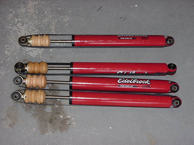
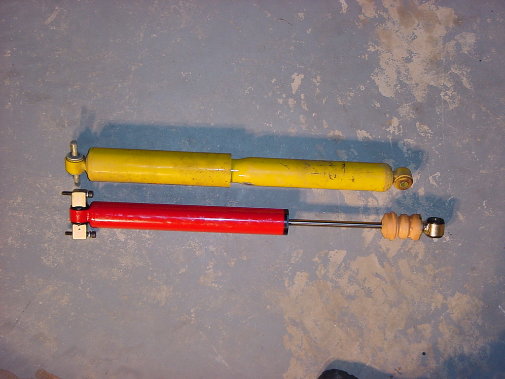
Here
are the OME shocks compared to the new Edlebrock shocks.
Front
Rear
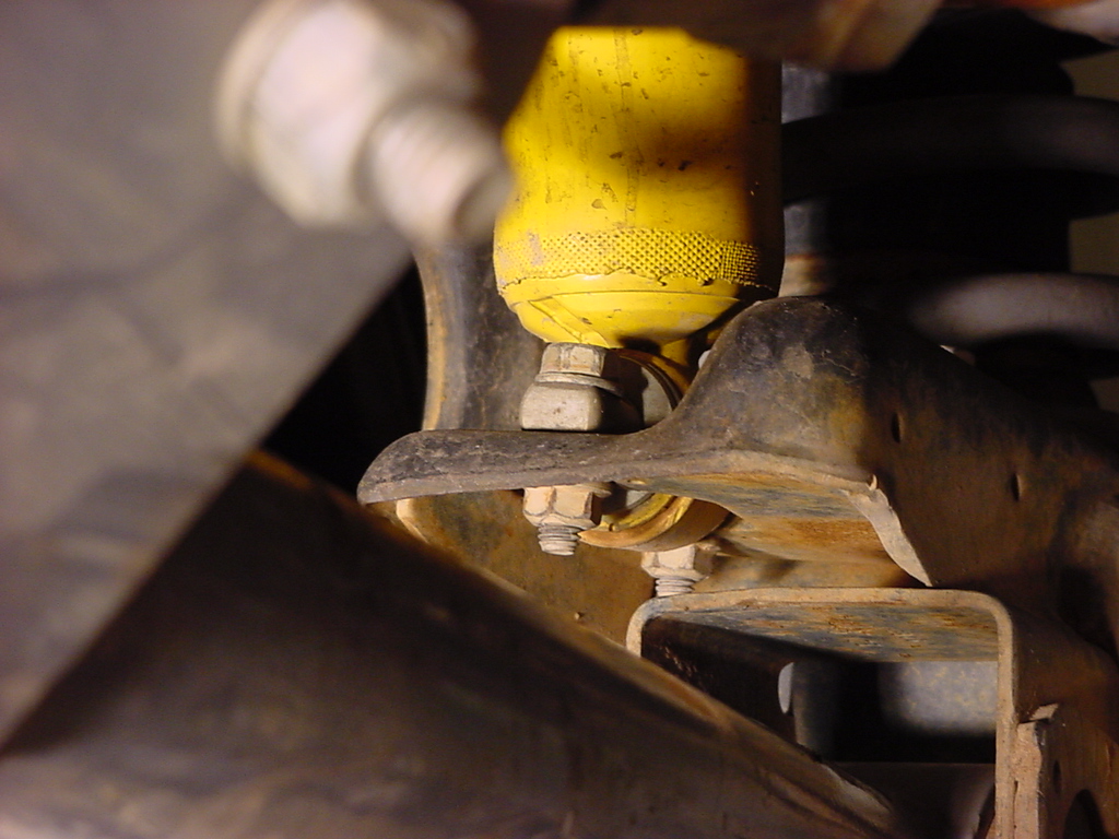
1. Mount
the front shock. Drill out the upper mounting hole to 7/8".
I was able to grind out this hole with a Dremel tool, but it requires
a steady hand and a lot of test fitting.
2.
Install the top nut. This nut requires quite a bit of force
to screw down. I used 2 (12") Adjustable wrench's.
Use 1 wrench to hold the top of the shock around the eye, and the
other to tighten down the nut. If you have a 1 1/4" Combo
Wrench you can use that on the nut.
3.
Bolt the bottom bar pin eliminators into the axle housing.
This requires a 1/2" Combo Wrench and a 1/2" Socket with
short extension.
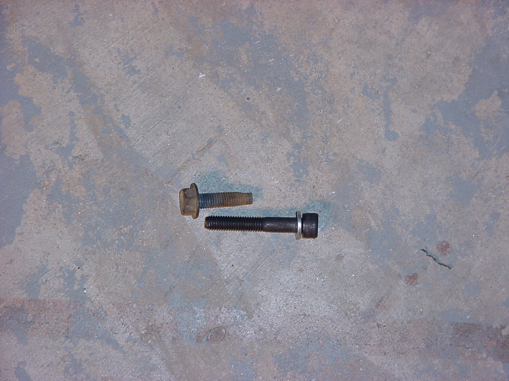
4. Install
the Rear Shocks. As you can see the bolts that came with the
JKS bar pin eliminators were to long to fit in the stock mounts.
I tried a few idea's but in the end I just used the cutting wheel
on the dremel to trim back the bolt.
5. Bolt
the shock in place with a 6mm allen wrench. This is a little
tight, but it can be done.
6. Reinstall
the lower shock bolt. Stock shocks require a 15mm and 18mm Combo Wrench
and/ or Socket.
Note: I already had the Tera Shock Relocators installed so they remained
and I attached the shocks in that location. Off Road Only does
have a set of rear shock relocators that you can weld together and
then weld to the rear LCA mounts. I was not a big fan of having
to fabricate and then weld up these so I didn't do them. I did
not experience any difference with the tera relocators.
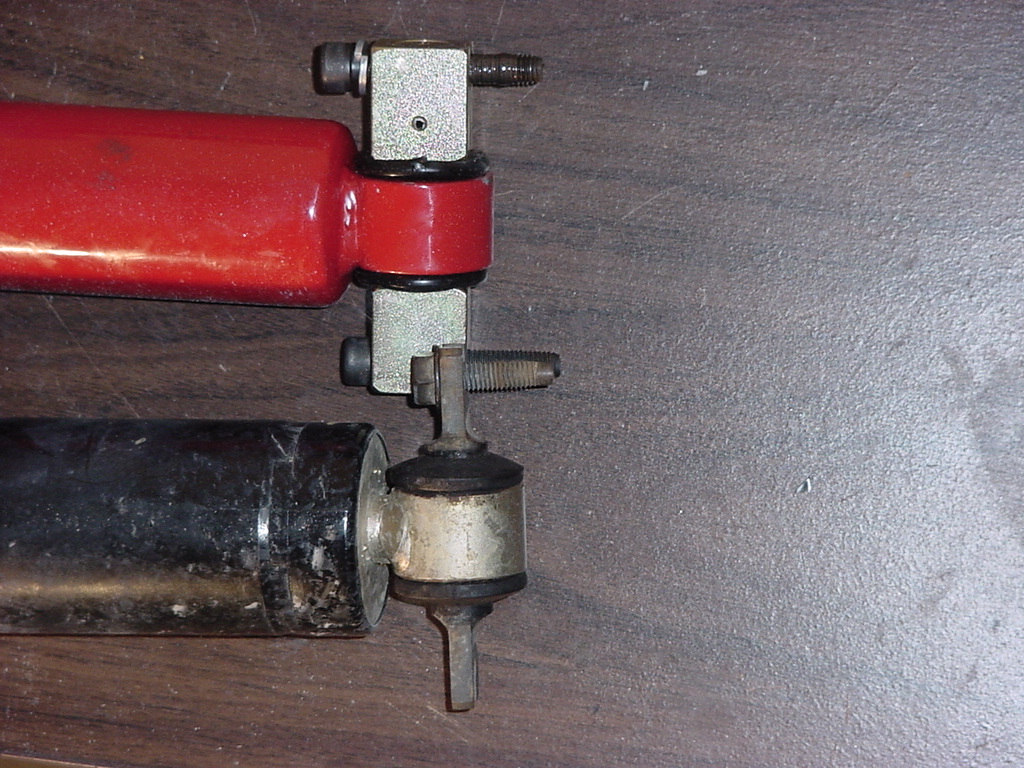
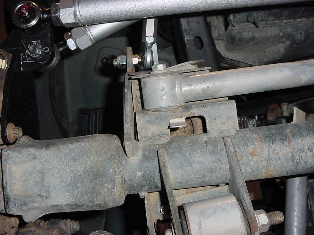
Rear
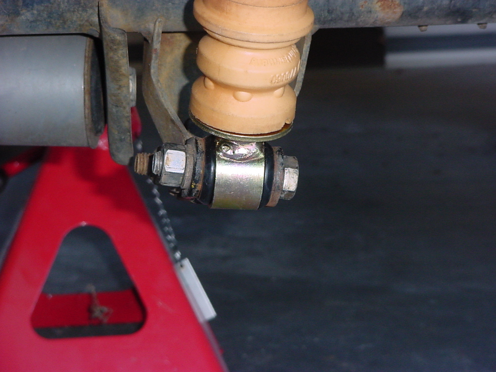
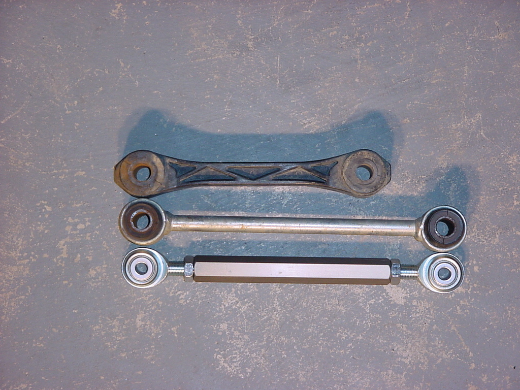
Anti-Sway Bar Links
Off
Road Only included these heim jointed rear anti-sway bar extensions.
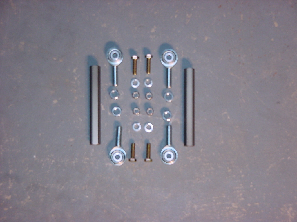
1.
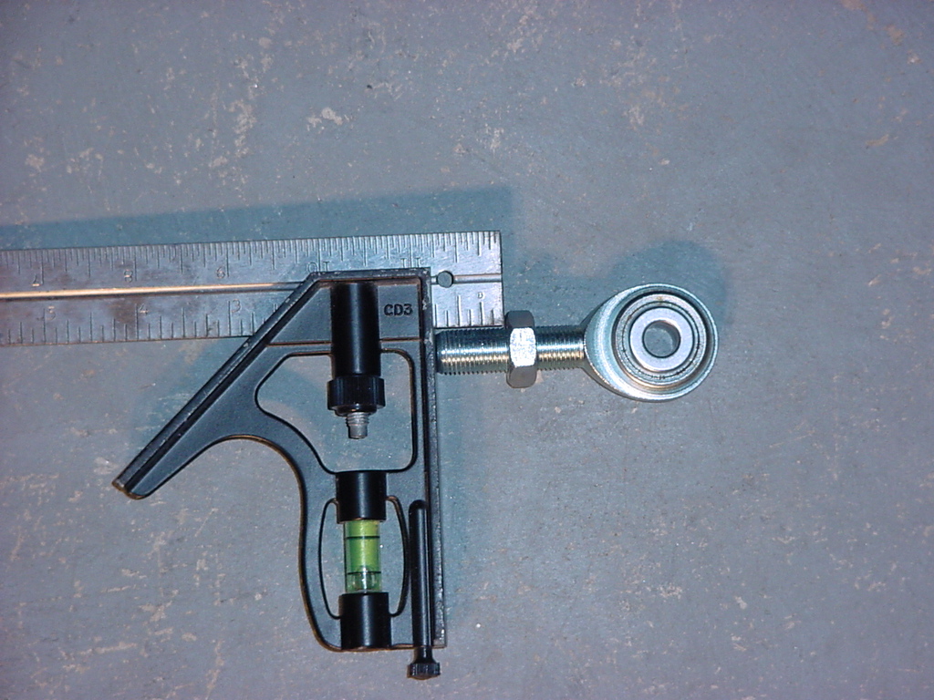
Assemble the links. Screw the nuts onto the Heim joints.
Adjust the nut so that it sit 1/2" in from the end.
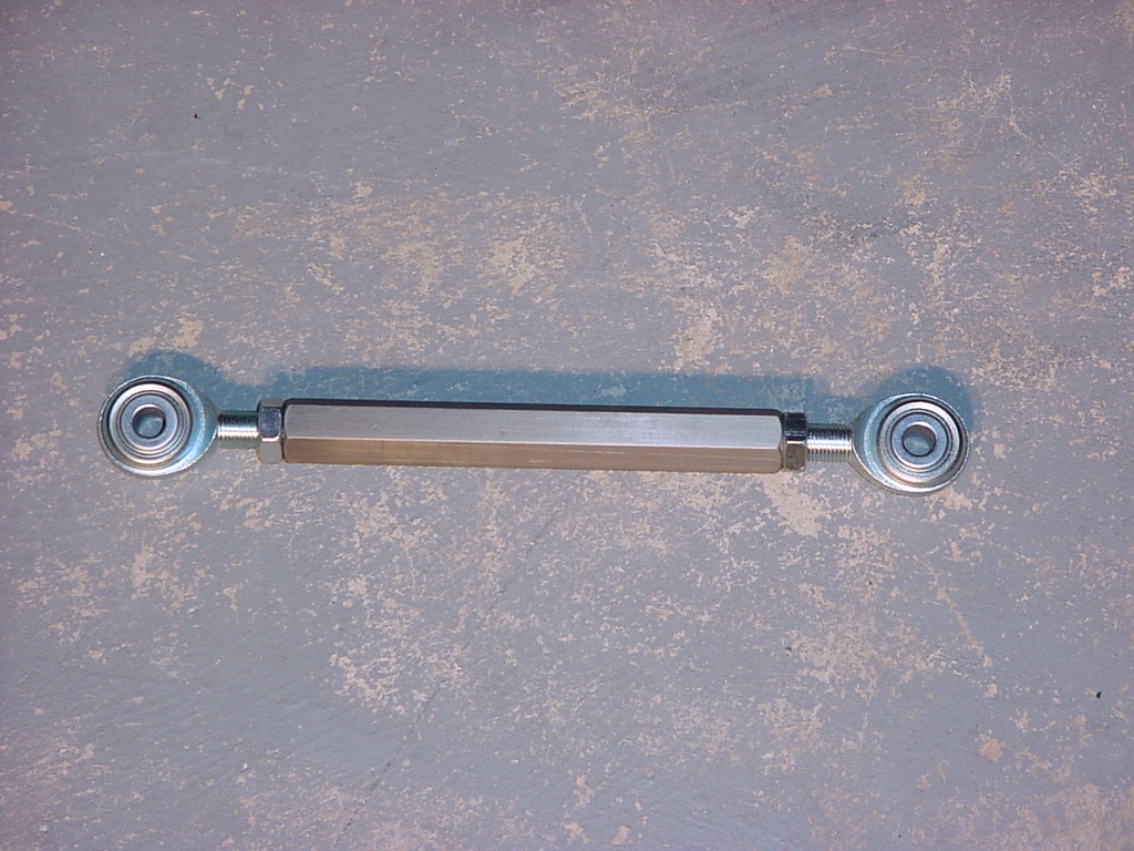
2.
Screw the heim's into the center section and tighten the Jam nuts
with (2) 3/4" Combo Wrench's. Note: Anti-seize the threads
on the Heim's before inserting into the center section. This
will minimize the corrosion due to dissimilar metals.
3.
Remove the rear anti-sway bar links. The top requires a 18mm
socket, the bottom a 15mm socket and 18mm Combo Wrench.
Here is the 3 links for comparison.
Factory
RE 4.5 Long Arm Link
ORO Heim Joint
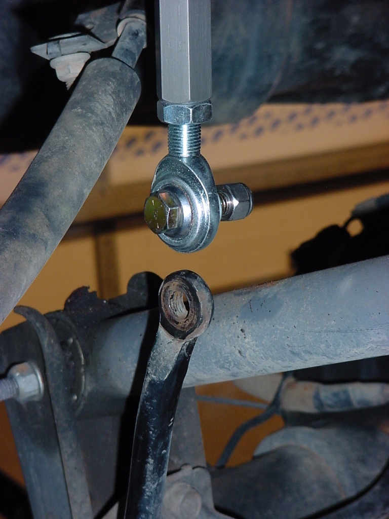
4.
Install the Links to the upper mount point on the frame. For
these you will need the longer bolts that you purchased above for
it to fit right. Insert 1 bolt through the heim, then lock
washer, then insert the bolt through the bracket on the frame.
Carefully install a nut on the bolt. This requires some patients,
and care since there is a hole that leads into the frame behind
this bracket. You will not be able to get the nut back if
it goes in that hole. You will need a 9/16" Combo Wrench
and Socket.
5.
Do not connect to the anti-sway bar yet. But I recommend putting
the hardware through the heim so that you don't lose it.
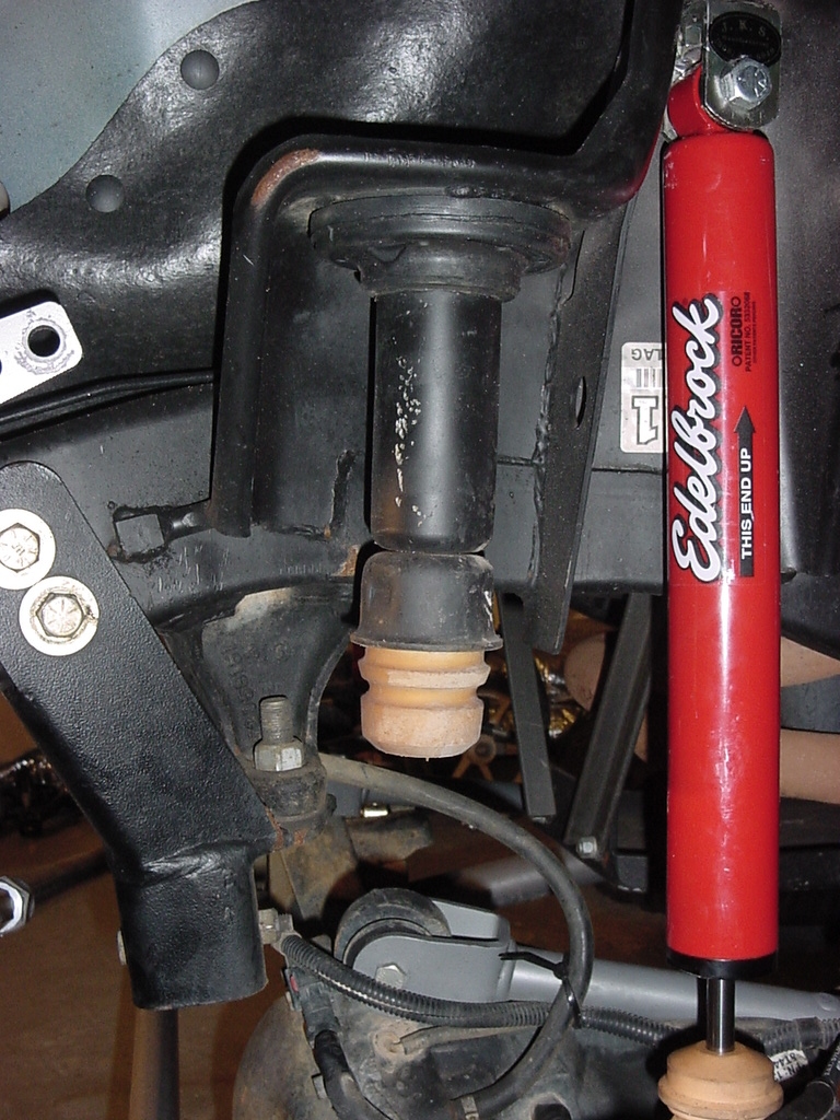
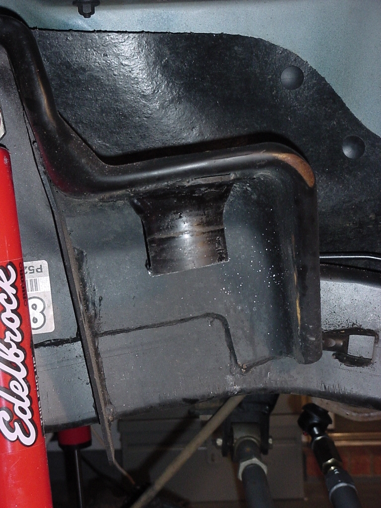
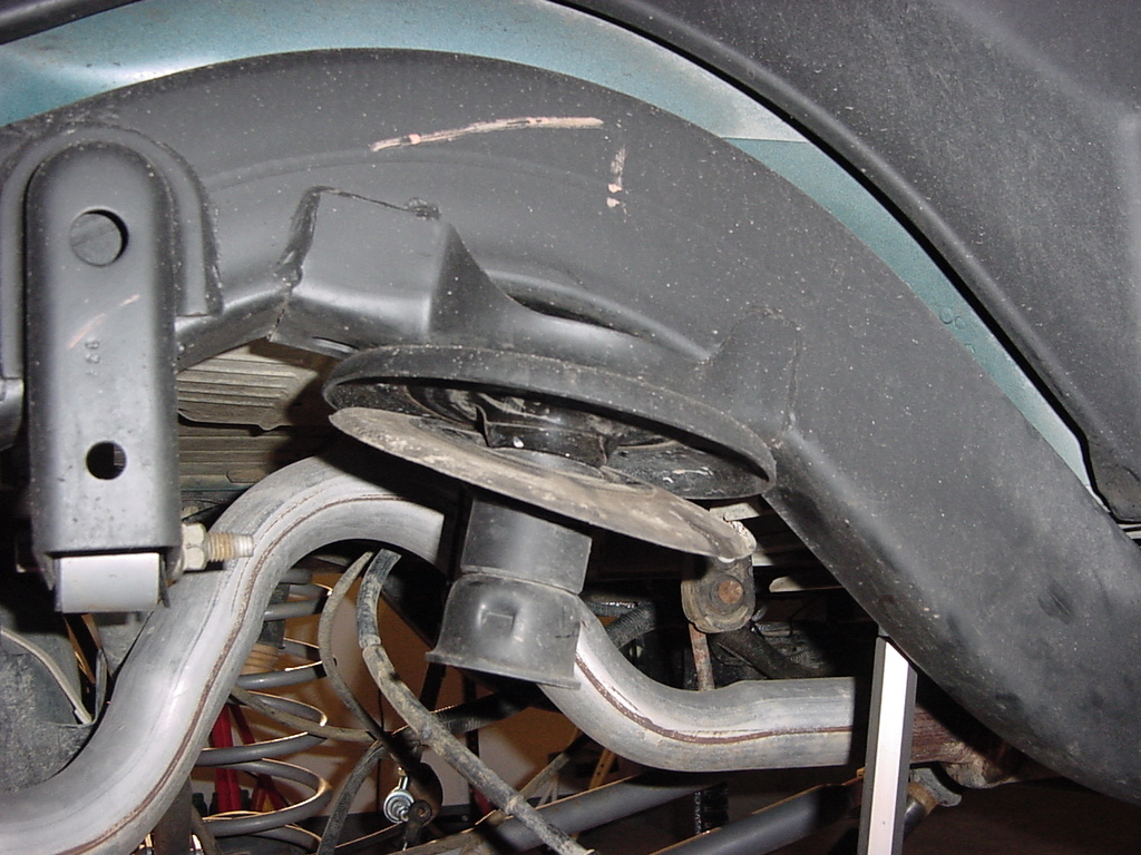
Front
Air Springs
You
may need to remove your front anti-sway bar links.
1.
Remove front Springs
2.
If you have the front spring clips installed, remove these otherwise
it's really hard to pull the spring out.
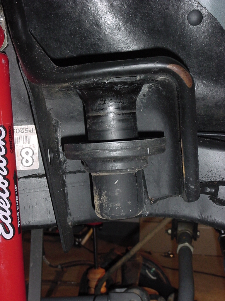
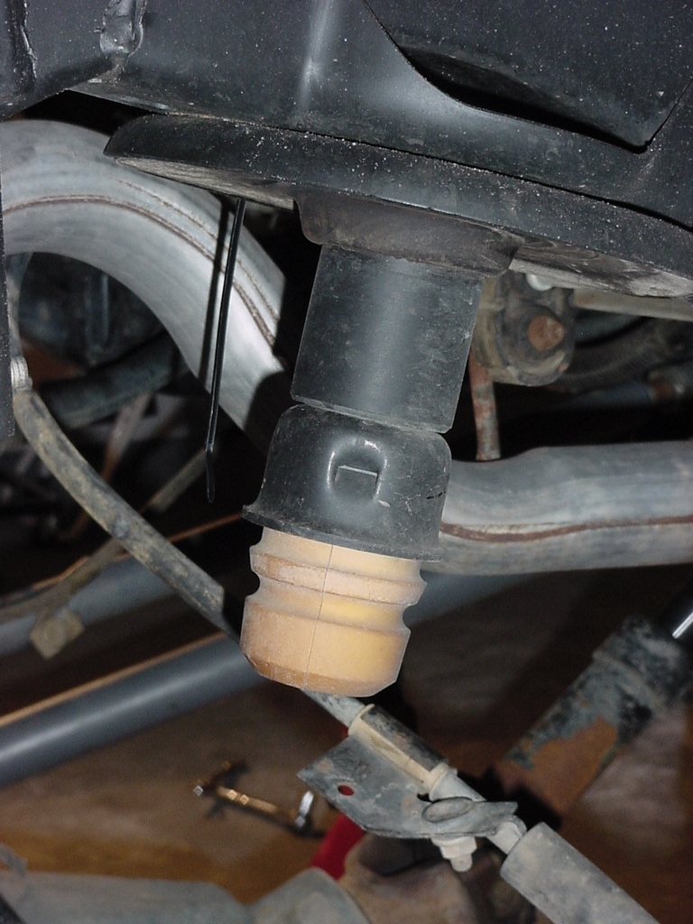
3.
Remove the front bump stop
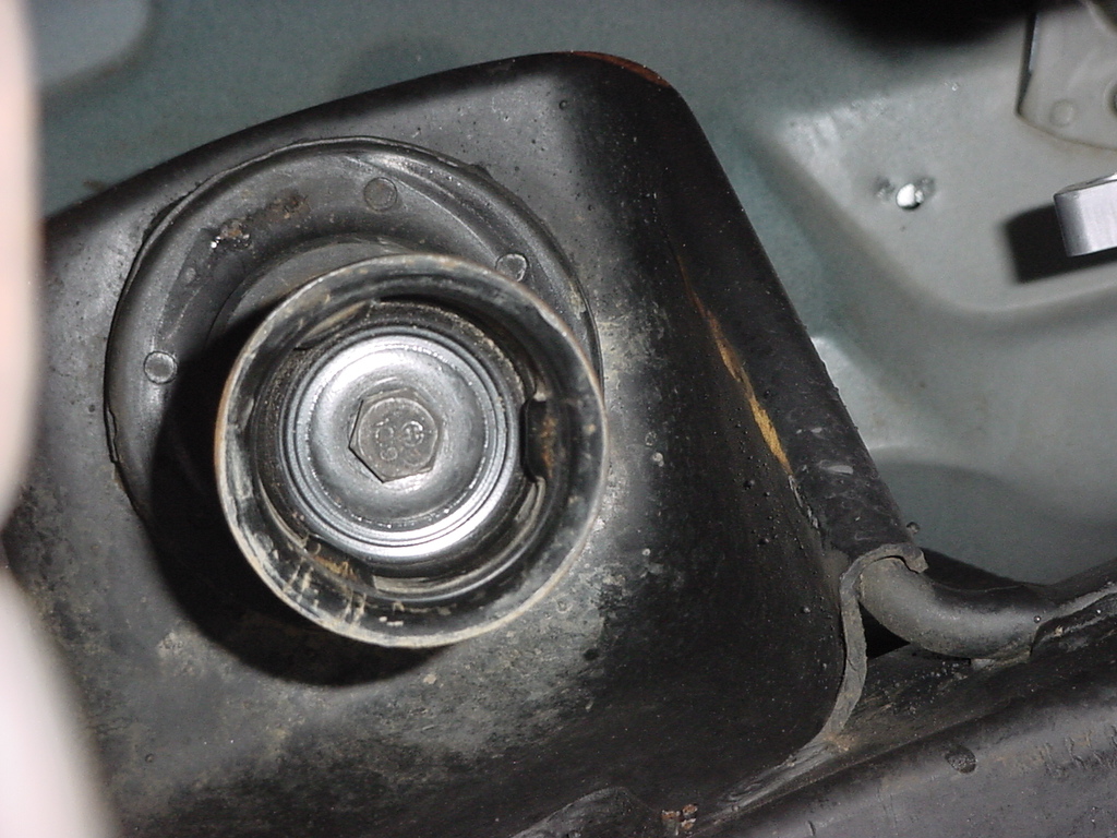
4.
Remove the bolt holding the cup on. This requires a 15mm Socket
and extension.
5.
Remove the Spring Isolator. You may need to twist the isolator
to break it free.
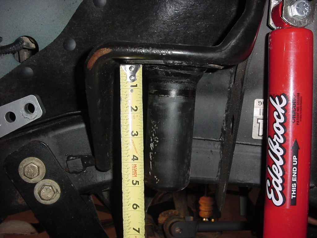
6.
Measure down 2" From the upper spring seat and mark a line.
7.
Cut off upper bump stop stub as shown.
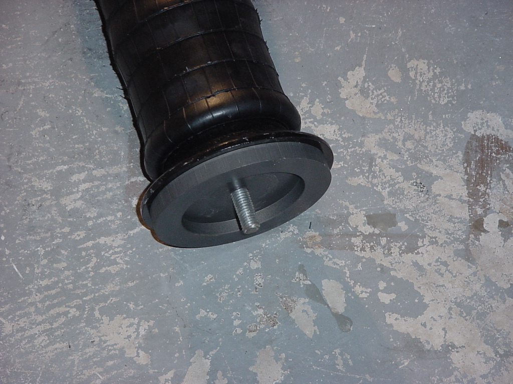
8. Remove
Nylock nut. Remove the front lower mount from the front air spring
assemblies.
9. Place
AiROCK lower mount on lower spring pad as shown. Mark the lower
spring pad for drilling.
10. Dill
a 1/2" Hole in the lower mount. Be careful, there may be
a space between the welded spacer (Rubicon model) and the top of the
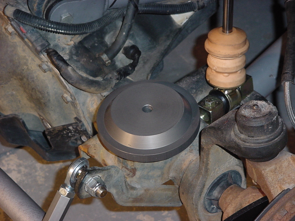
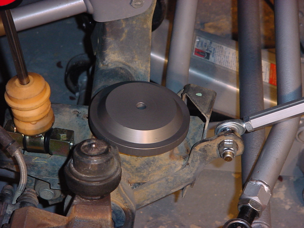
spring pad. Debur the hole making certain that the pad it flat.
11.
Verify that the plate sits flat on the spring pad and that the holes
line up.
��
12.
Trip the web between the shock and the cut bump stop mount.
This is to prevent rubbing of the air bag on the point of the web,
that could cause a tear in the bag. A template is provided.
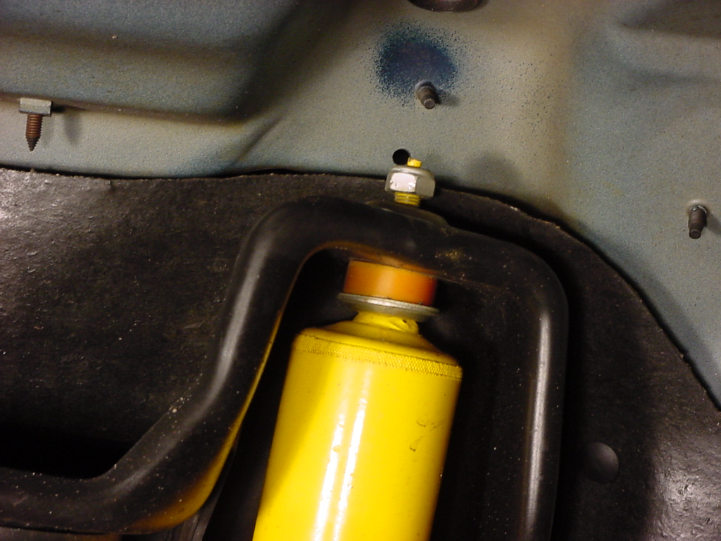
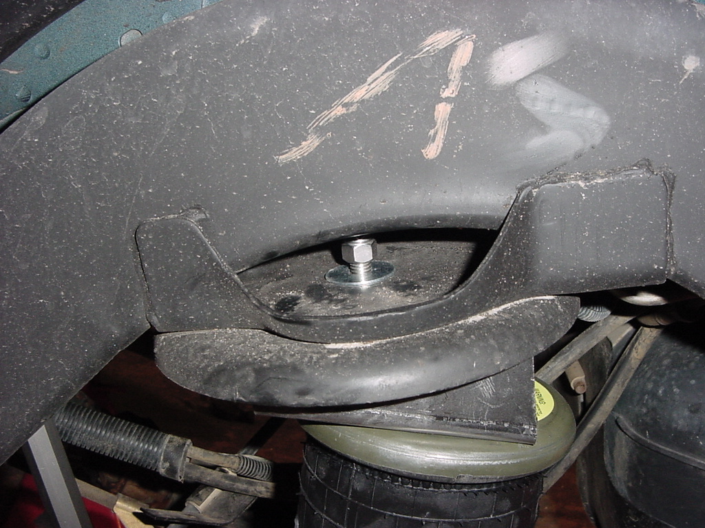
13. Remove
upper front mount nut and washer (big metal plate). Test
fit the air springs over the bump stop stub that you cut earlier to
verify enough has been removed.
14. The
driver side is the easier of the two to install. Place the Air
Spring assembly on spring pad. Install Nylock nut, but do not
tighten. On the passenger side I just set the air spring assembly
on the spring pad.
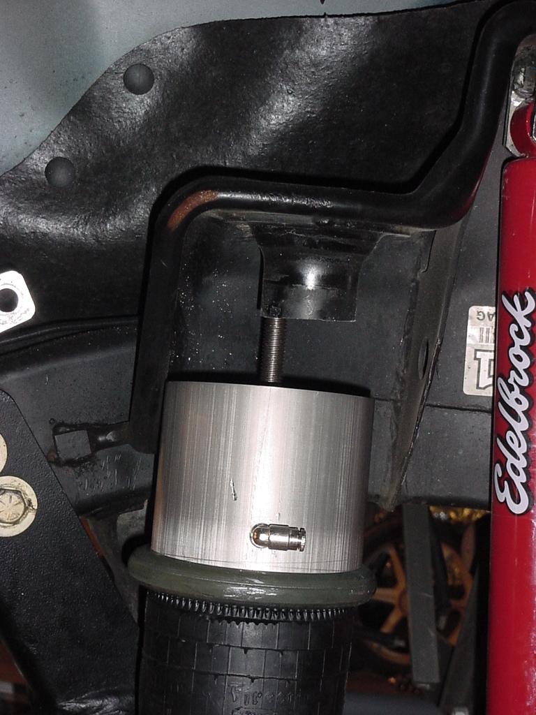
15.
With a floor jack, lift the axle and guide the 2 upper assemblies
into and around the cut off bump stop stubs.
16. Rotate air spring assembly until
air fitting is towards the front of the vehicle.
17.
Install washer (big metal plate) and Nylock nut. TIghten nut
with a 3/4" Deep well socket.
��
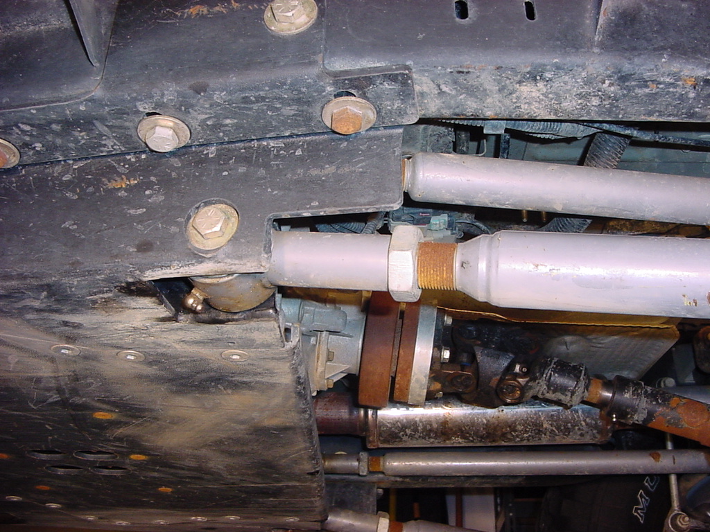
18.
Now remove the bolt holding the front track bar to the axle.
You will need room to thread the Nylock nut up and into the cavity
below the spring pad.
��
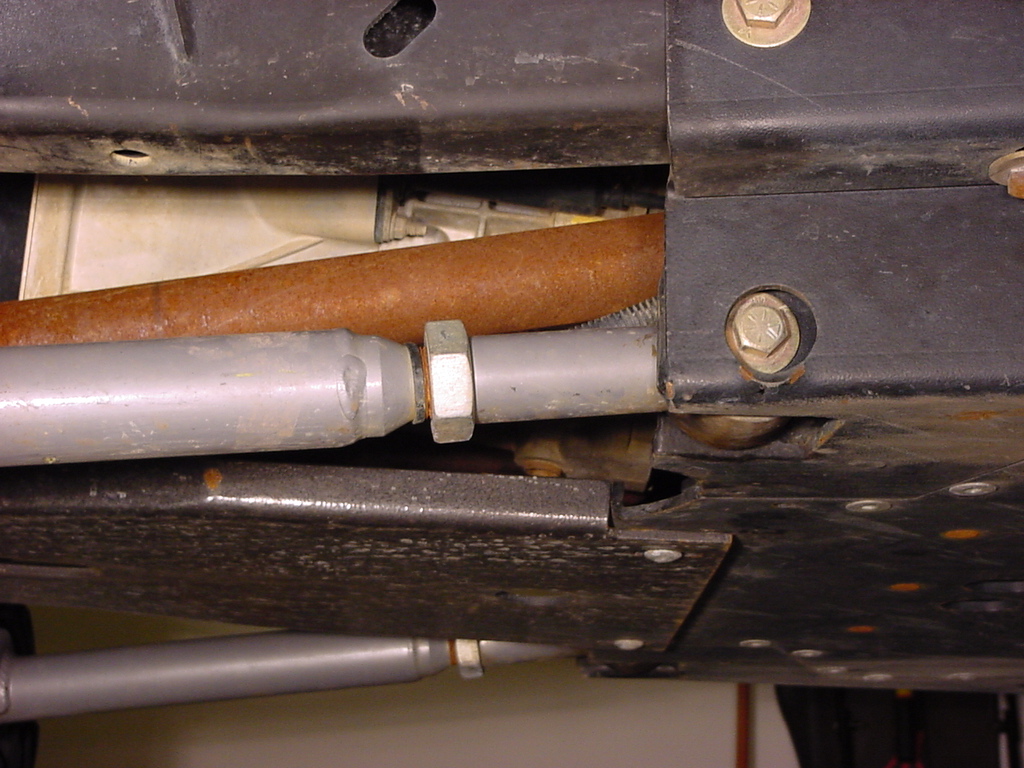
19.
Unscrew the bolt with a 15mm socket. You won't need to pull
the bolt out all the way, just enough to remove the nut and clear
the space behind the track bar.
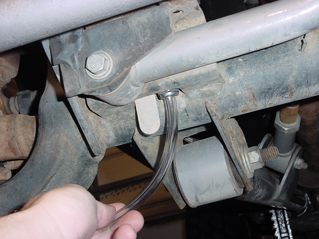
20.
Using the supplied 6" piece of 7/16" clear tubing place
the nylock part of the nut over the end of the tube. Some
kits my already have a spare nut installed on the tube.
21.
Feed the nut up into the cavity and install on bottom of air spring.
Utilize the hose to start the Nylock nut on the lower right mount.
This takes some patients to accomplish.
��
22.
Feed a 3/4" crows foot wrench and small extension up into the
cavity to tighten down the nut. Do not fully tighten.
��
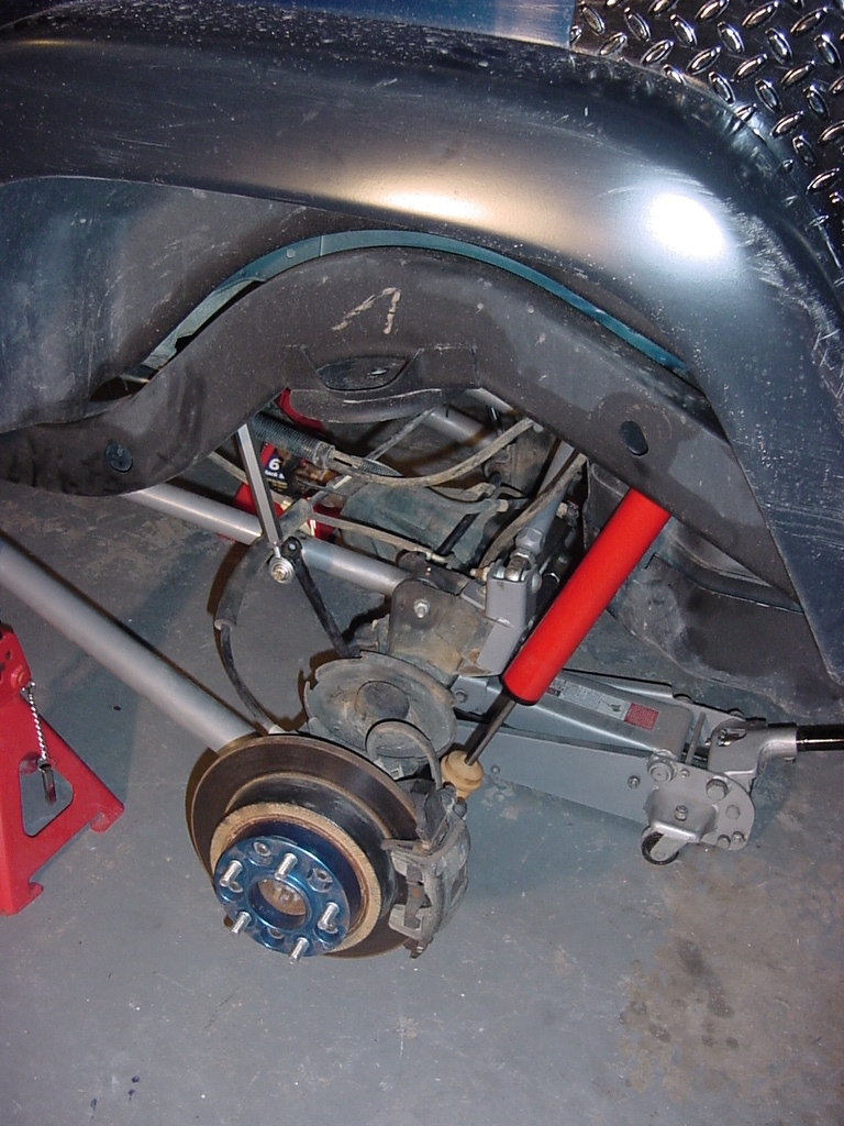
Rear
Air Springs
1.
Remove Rear Springs
2.
Remove the Rear bump stop
3.
Remove the bolt holding the cup on. This requires a 15mm Socket
and extension.
4.
Remove the Spring Isolator. You may need to twist the isolator
to break it free. Some
TJ's may have come with a lower mount isolator also, so check the
lower mount for the same.
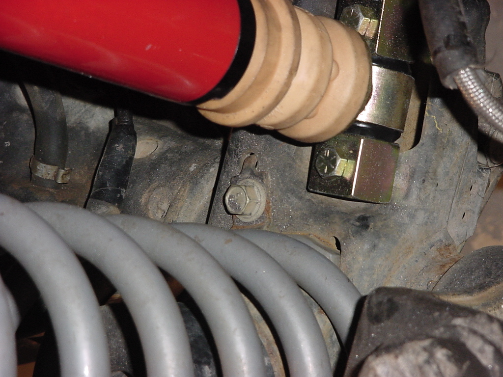
5.
Clean off both mount surfaces. Mine had a lot of dirt caked
into this area. You need to have a flat mount surface for the
air springs. Check the bolt for the rear track bar at the frame
mounting point. Ensure that the bolt does not protrude more
than 1/4" thru the nut. If it does, cut the bolt flush
with the nut before installing the right rear spring. This will
prevent the bolt from rubbing a hole into the air spring.
6.
Drill the upper bump stop thread with a 3/8" Drill bit.
7.
Mark the center of the lower spring pad and drill out to 1/2".
8.
Remove the Nylock nuts from the top and bottom mounting studs on the
air spring assemblies.
9.
Test fit the air spring assembly onto the lower mount to ensure that
the bolt clears the axle assembly underneath. I had to trim
both of mine for clearance.
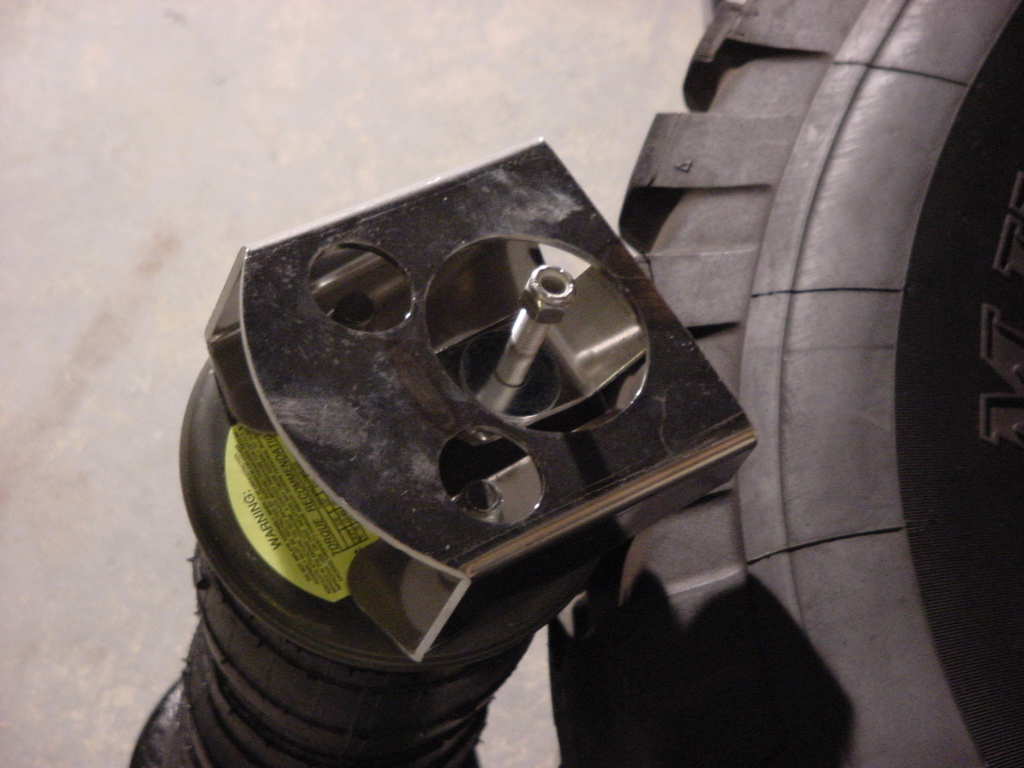
10.
Install rear air spring with the wedge of the upper mount pointed
towards the front of the vehicle.
11.
Install washer and nylock nut on top of upper spring pad to hold air
spring assembly. Tighten with a 9/16" Combo Wrench.
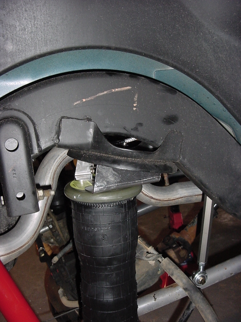
12.
Maneuver, rear axle up with the floor jack to insert the lower air spring
mounting stud through the hole in the lower spring pad. Install
lower nut with 3/4" Combo Wrench. Do not tighten yet.
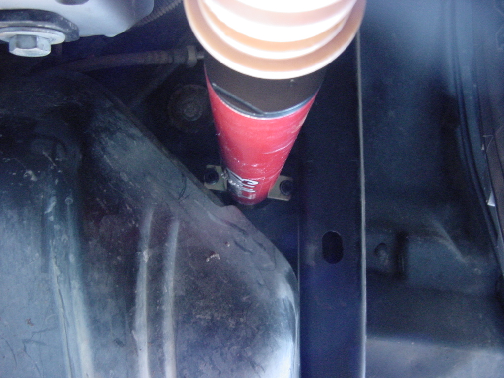
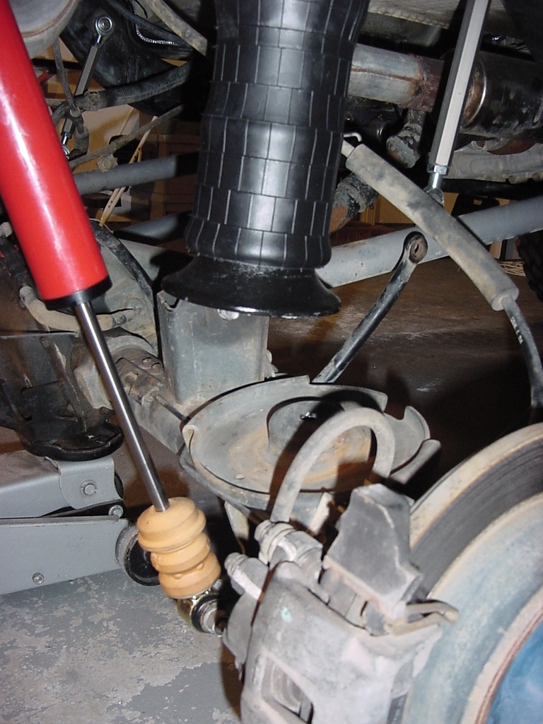
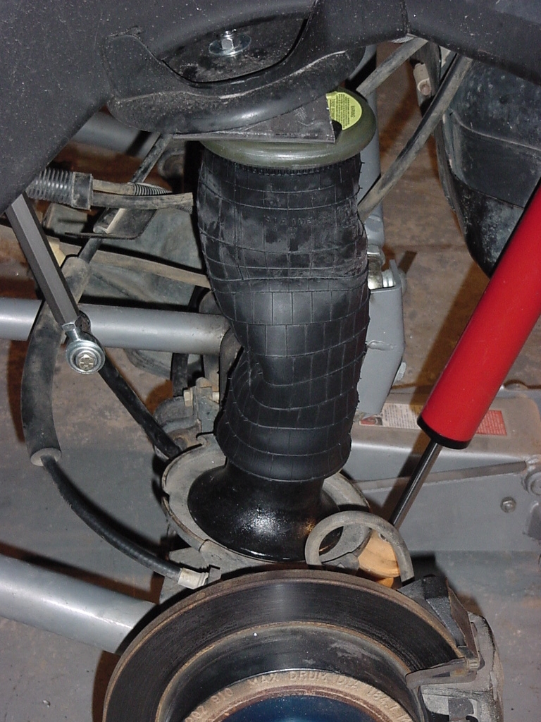
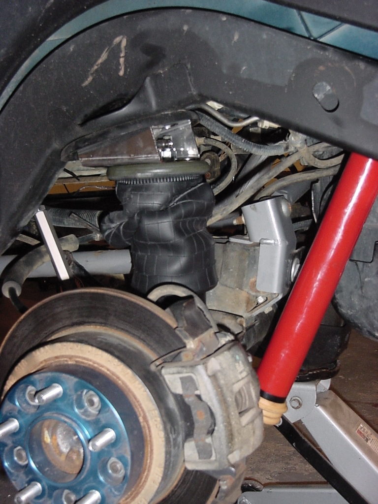
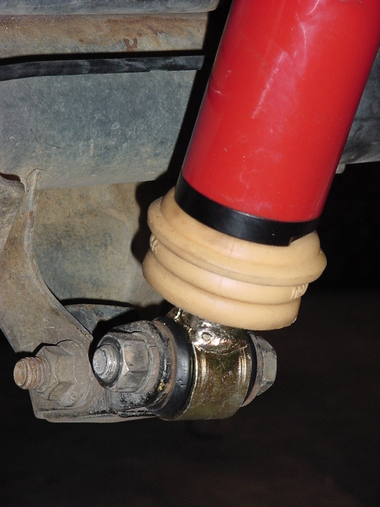
Installed.
Fully Extended
Fully Compressed
Max compression on bump stop
Final
Steps
1.
Route airlines from ACU to individual air bags. Insert airline
into fitting, once air line is inserted into fitting, pull on airline
to seat seal. If airline is held captive your connection is
complete. I followed the routing of the wires for the two
rear air springs, and ran the fronts down through the large hole
in the fender well near the air springs.
2.
Recheck all your torques on your bolts. Install rear anti-sway
bar drop brackets. At this point the only Nuts that should
still be loose are the 4 lower air spring nuts and the bolt for
the front track bar to axle bracket.
3. Ensure that all electrical connections
are made.
4.
You need to be ready to pressurize the system at this point.
Reinstall all tires and remove vehicle from Jack stand. Lower
vehicle slowly down onto the bump stops for the shocks.
5.
Turn vehicle on and pressurize air system.
6.
Install the ACU fuse and verify that the controller display lights
up with the "AiROCK" message.
7.
You will need to scroll through the setup to find the test air spring
selection. Refer to operators manual for further information.
8.
Pressurize the Air Springs to 25psi and check for leaks in the system.
I recommend turning off the Jeep once you have all springs to 25psi.
9.
Tighten all lower air spring nylock nuts.
10. Reinstall front
track bar bolt.
11. Restart Jeep and
proceed with air spring calibration. Note: Front anti-sway bar
should be disco'd if using Quick disco's, or swayloc should be disengaged.