My factory battery suddenly decided that it was time to die and left me stranded. Nothing more embarrassing than haveing to get jumped by a Fordin the mall parking lot to get myself home, so time for a dual battery system since I had to replace the battery anyways. I have had dual batteries before and it has always been, buy the tray, and then piece together the parts for the isolator and cables. Not anymore, now you can get everything you need from Genesis Offroad. I was impressed with the quality that went into this setup. Everything is there, tray, isolator, cables, grommets, connections for auxiliary wires, even a momentary switch to connect the batteries so that you can self jump yourself and get home. No more stuck at the mall for me! I did choose the 200 amp isolator since I had a winch and intentions to add a few other options like a big power inverter later. Even if I don't add those other accessories, the bigger isolator is just piece of mind. The instructions from Genesis to install this system are absolutely awesome. Very detailed. I did a few things in different order, but otherwise pretty much just copied their instructions below.
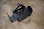
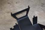
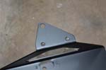
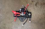
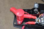
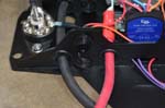
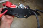
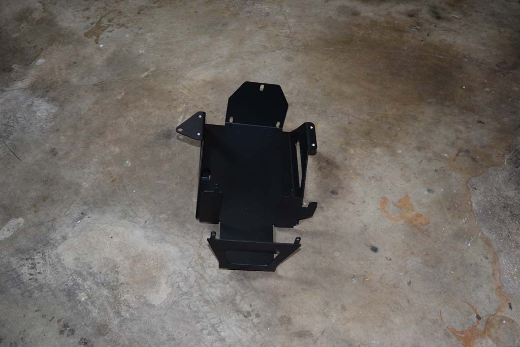
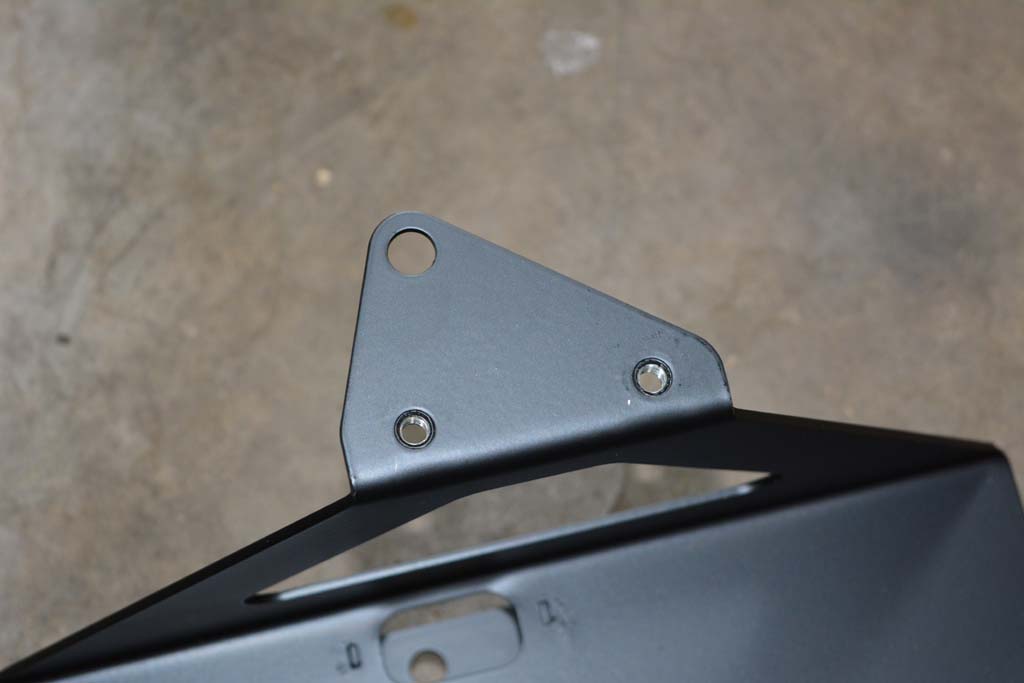
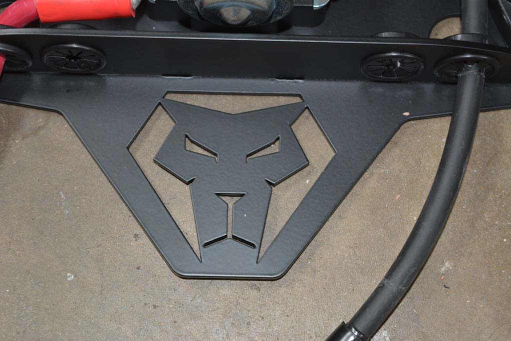
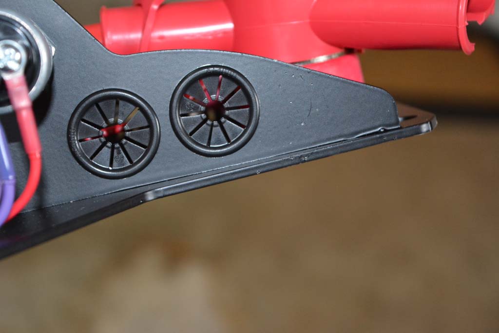
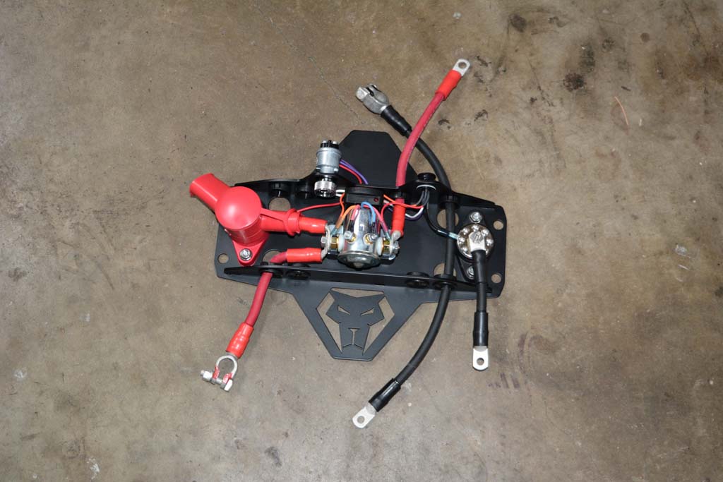
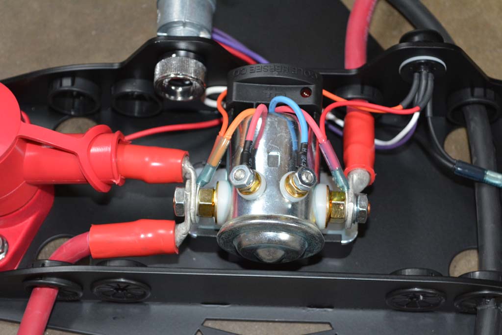
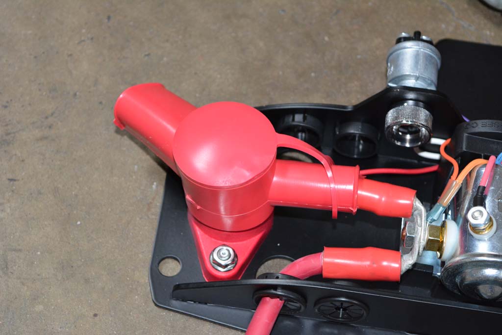
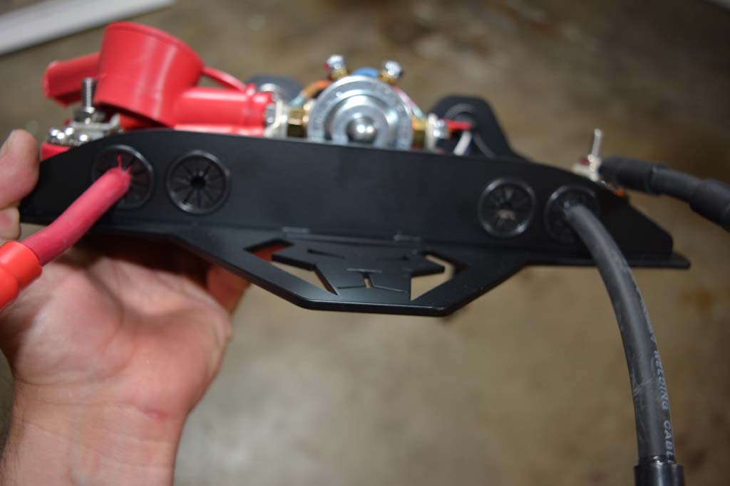
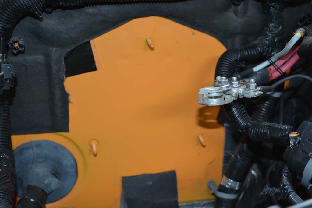
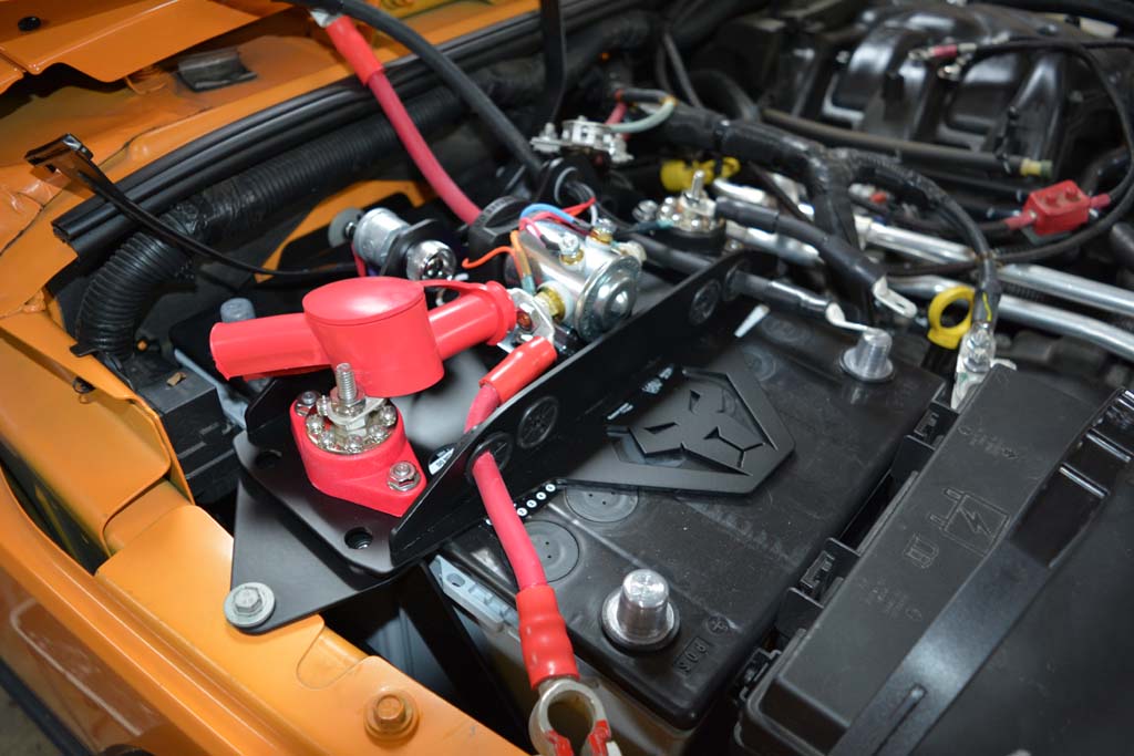
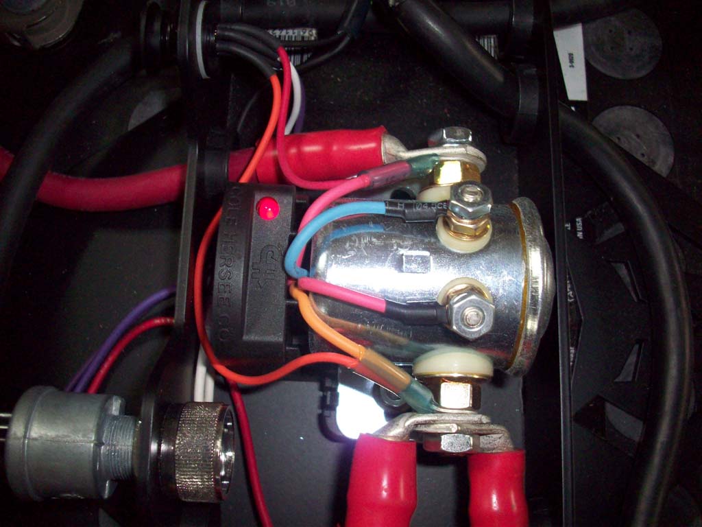
The top cover plate has several innovative features in a simple package. All of the wiring has already been done for you, and the smart isolator comes pre-installed. The welded gussets on top have holes with grommets to route the wires directly to the correct battery post, so there's no guess work involved to make the connections. Use the extra grommets for routing your own accessory wires cleanly and neatly to the power and ground bus bars. High quality battery terminal connectors are soldered and crimped to the flexible 2 gauge wire connecting the batteries together. With all the wiring integrated into the top plate, servicing your batteries has never been easier. Simply pull the terminals off the battery posts, remove the 4 easily accessible stainless fasteners securing the lid and all the wiring can be lifted up and out of the way to service your batteries when necessary.
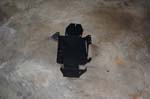
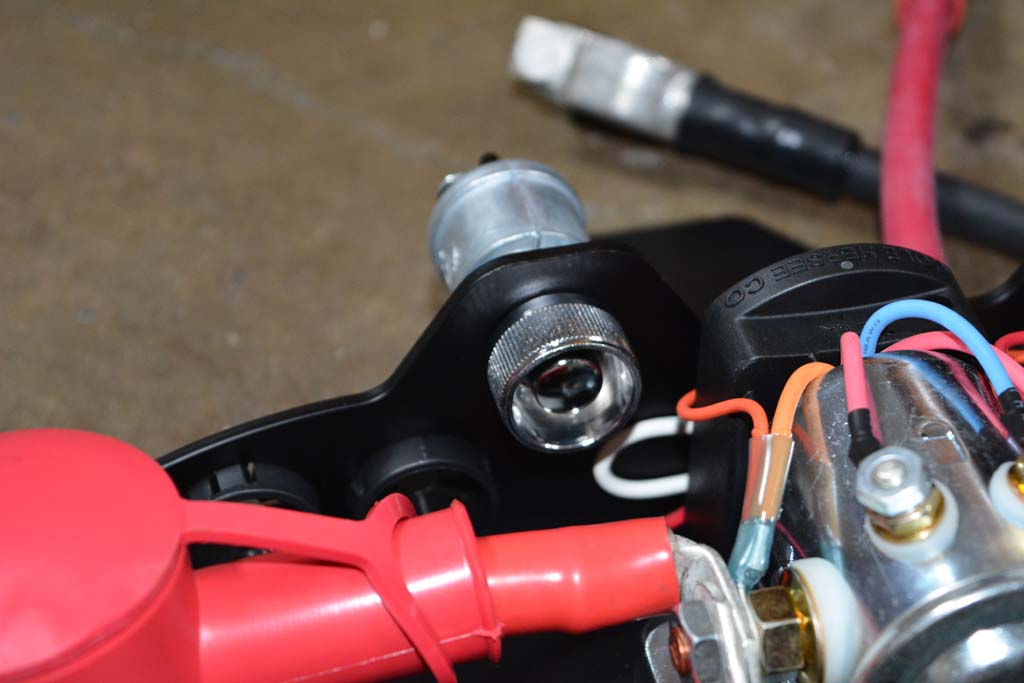
The included smart isolator gives you automatic control of all the charging functions with no interaction required.
Here's how it works.
What if your cranking battery is somehow drained down too low to be able to start the vehicle? We have a solution for that.
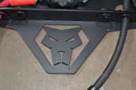
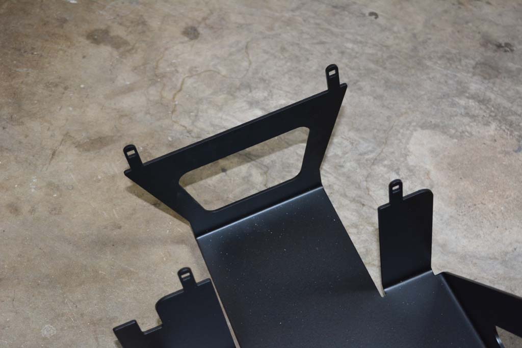
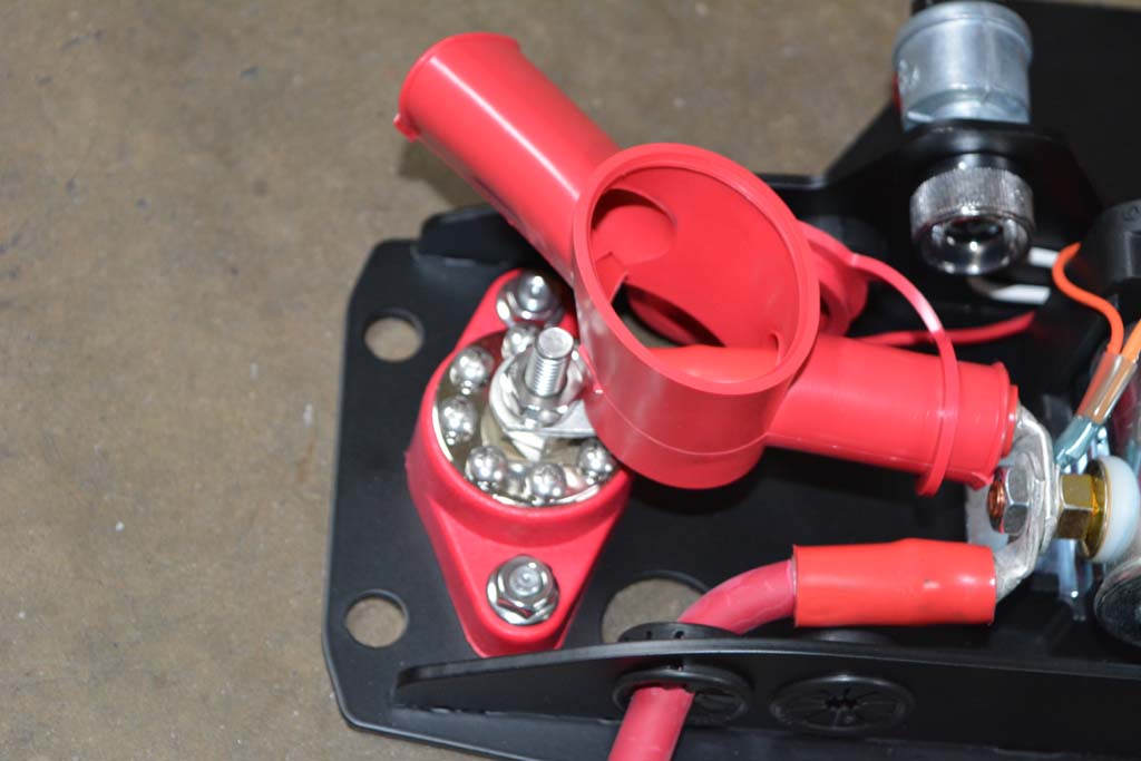
Also includes high amp power AND ground bus bars. The bus bars are already pre-wired to the accessory battery. Now you can quickly and easily connect your winch, lights, amplifiers, and lots more while keeping the wiring neat and orderly. Your winch or other high-amp accessories go onto the large center post on the bus bars, and all your other accessories go directly to the smaller screw terminals on the bus bars.
NOTE: 2007-2011 model years require a short extension cable for the evap solenoid. The extension is made with OEM connectors and wires to ensure a perfect watertight fit for easy installation. This piece is not required on 2012+ JKs. Be sure to specify your year model when ordering.
Works with aftermarket air intake systems that use the factory air box space.
| What is in the box: |
| Someone told me when they were checking out the system that it was "The Cats Meow..." at this point I realized I needed to hang out with some younger people. |
 |
 |
 |
 |
 |
 |
 |
 |
 |
 |
 |
 |
 |
 |
 |
 |
 |
|
|
|
| |
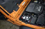
| Battery Removal: |
| 1. Disconnect all or your accessories and get them out of the way. |
 |
 |
 |
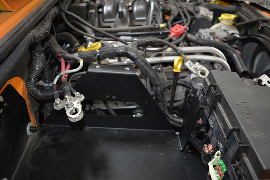
2. Disconnect NEGATIVE battery cable first, then disconnect positive cable. Secure cables out of the way. |
 |
 |
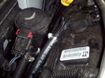
3. Use a 10mm socket with a long extension to remove the factory battery hold down bracket located between the battery and the fender. |
 |
 |
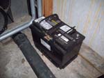
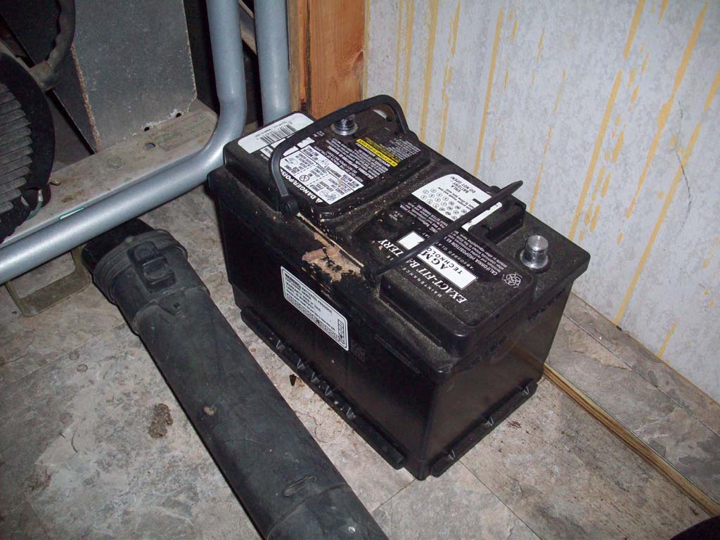
4. Remove the factory battery and set it out of the way. |
 |
|
| |
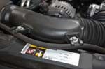
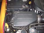
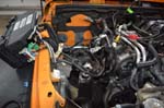
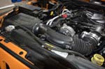
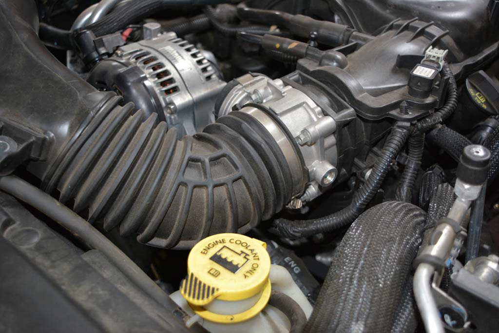
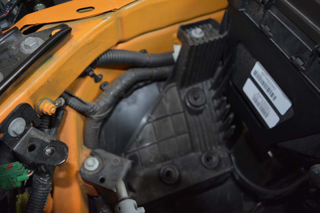
| Intake and Airbox removal: |
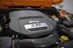
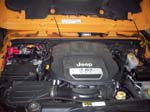
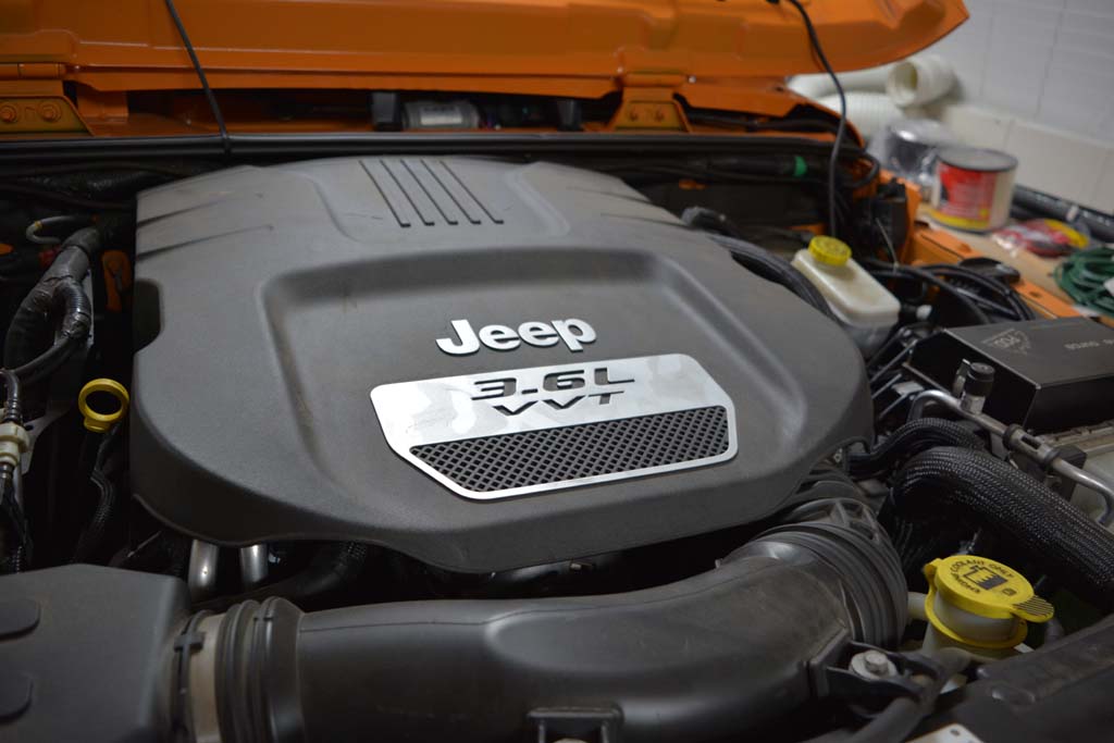
1. Lift and remove the engine cover piece |
 |
 |
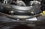
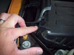
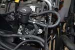
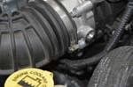
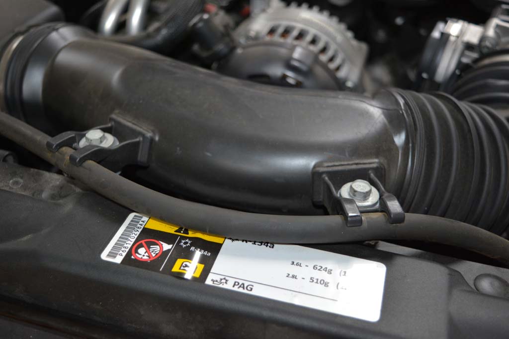
2. Disconnect the radiator overflow tube and two 10mm bolts securing the air intake. |
 |
 |
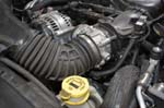
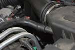
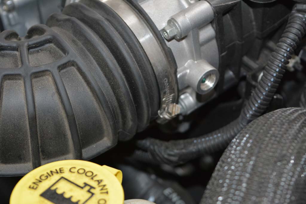
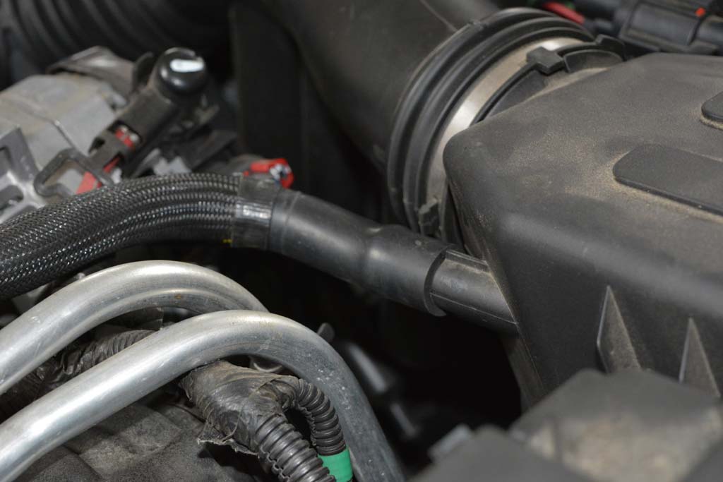
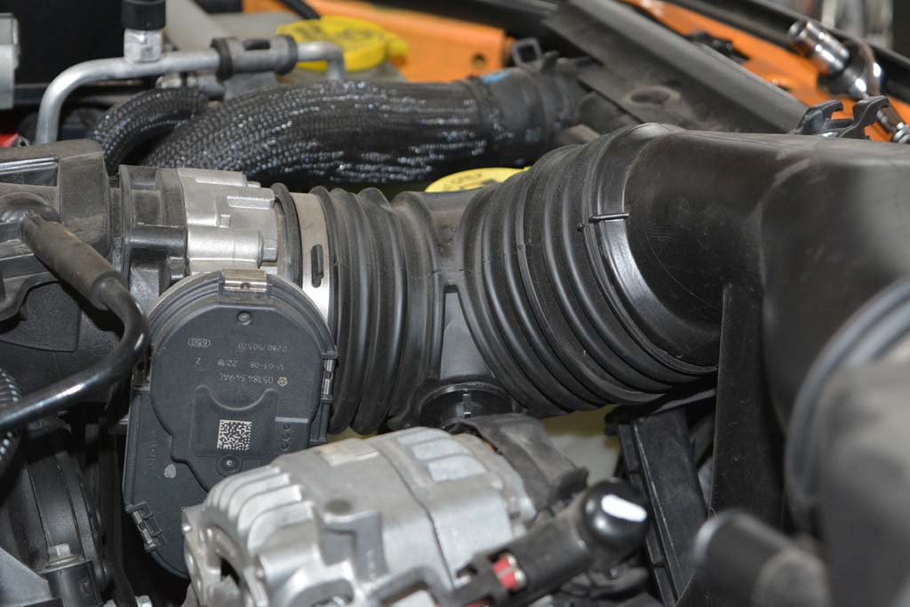
3. Loosen hose clamp connecting the air filter box to the intake tube with a flat tip screwdriver. |
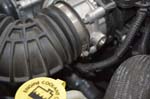 |
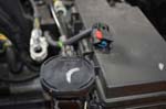
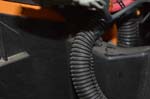
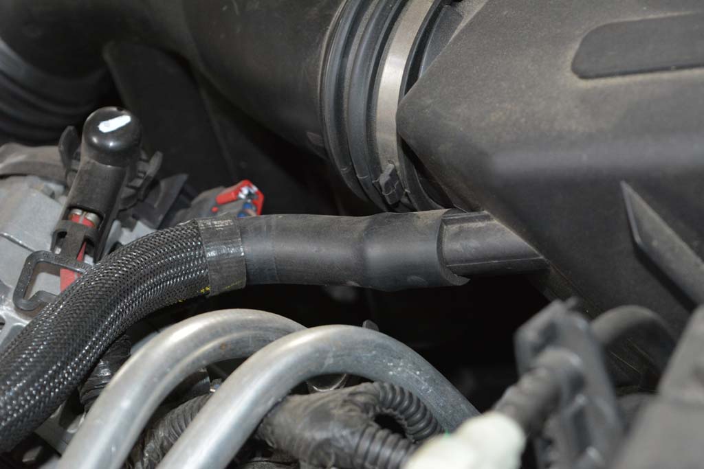
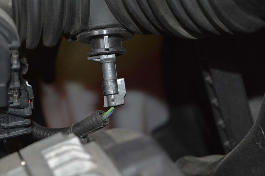
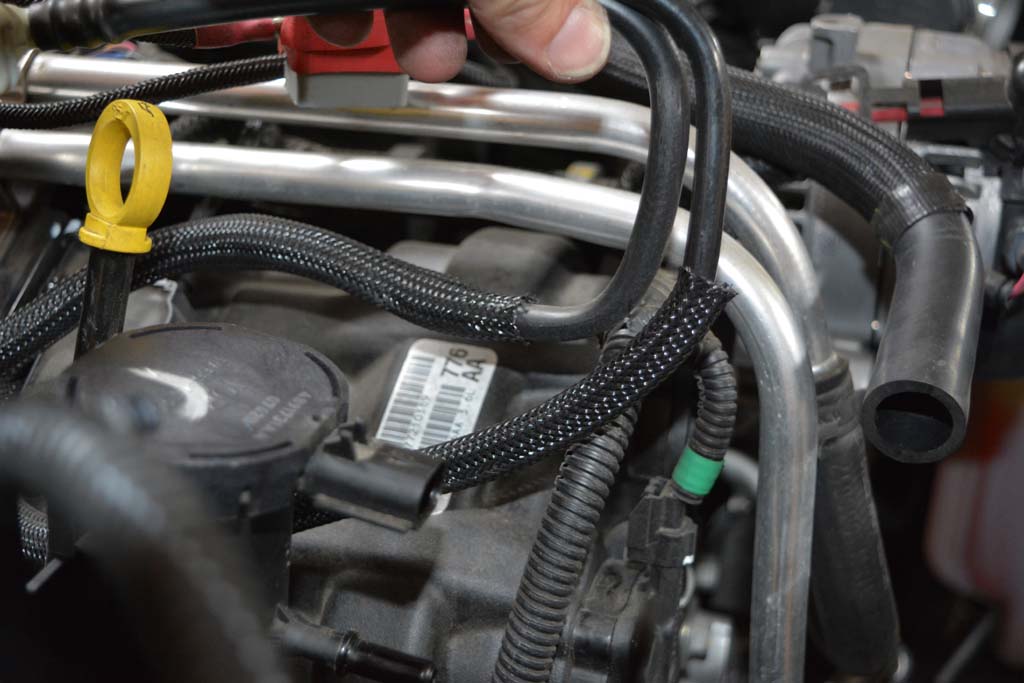
4. Remove the crankcase vent hose from the air filter box by twisting and pulling until it comes off. Do not pry on the hose with any tools. |
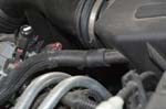 |
| Disconnect the IAT sensor harness from the IAT sensor. There is a small tab on the side of the sensor right by the wire. Doesn't take much to push it and disconnect the harness from the sensor. |
 |
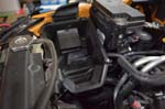
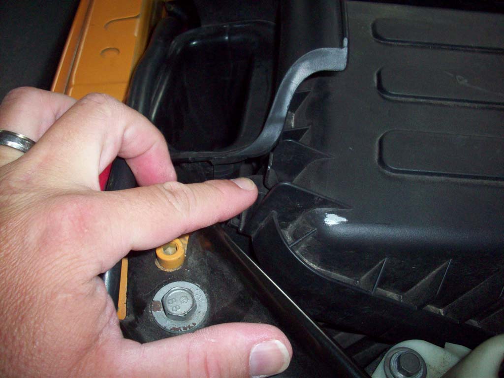
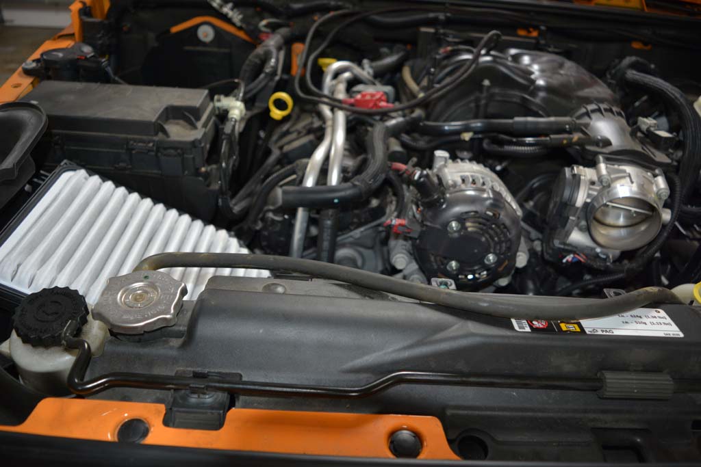
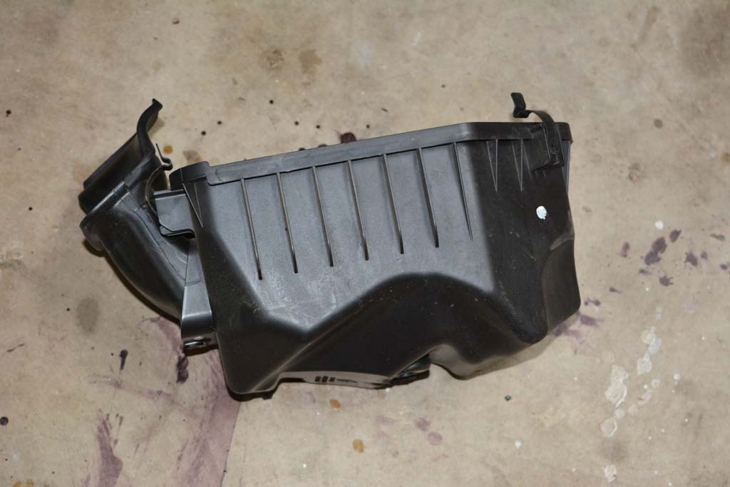
| 5. Unfasten the top of the air filter box and remove the top cover and intake tube from the engine. |
 |
 |
 |
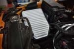
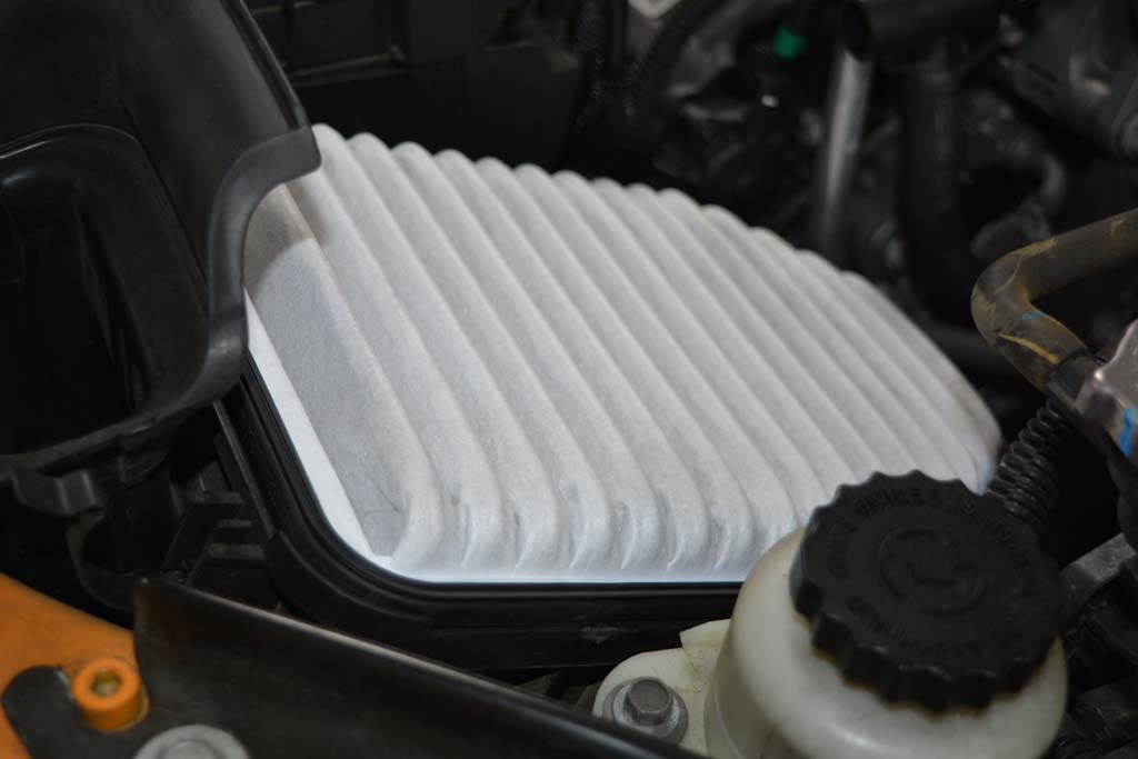
Remove the Air Filter |
 |
 |
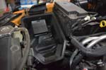
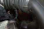
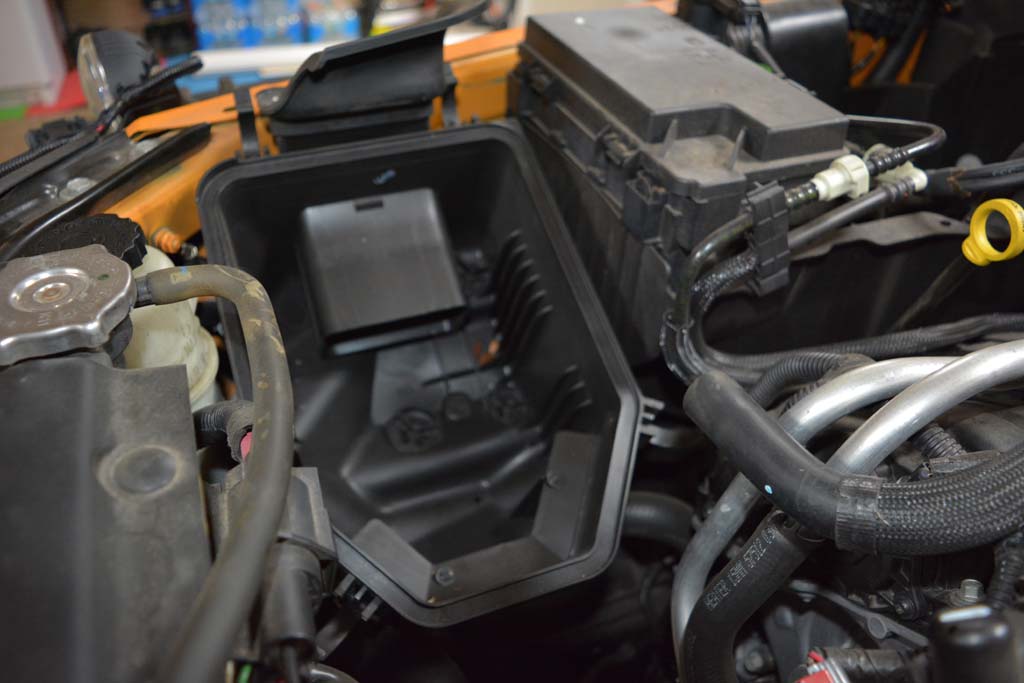
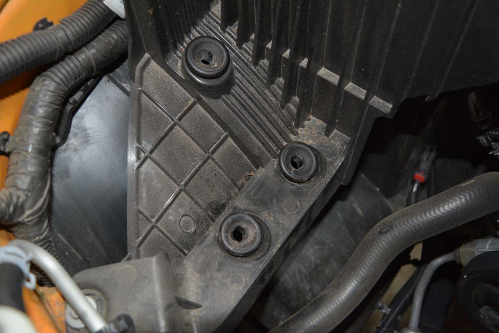
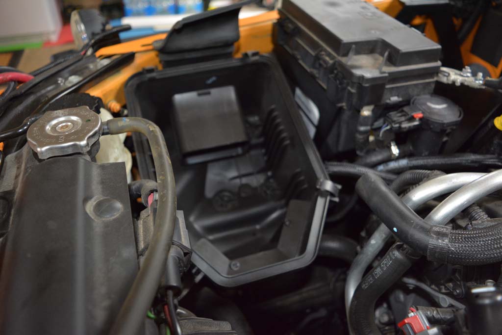
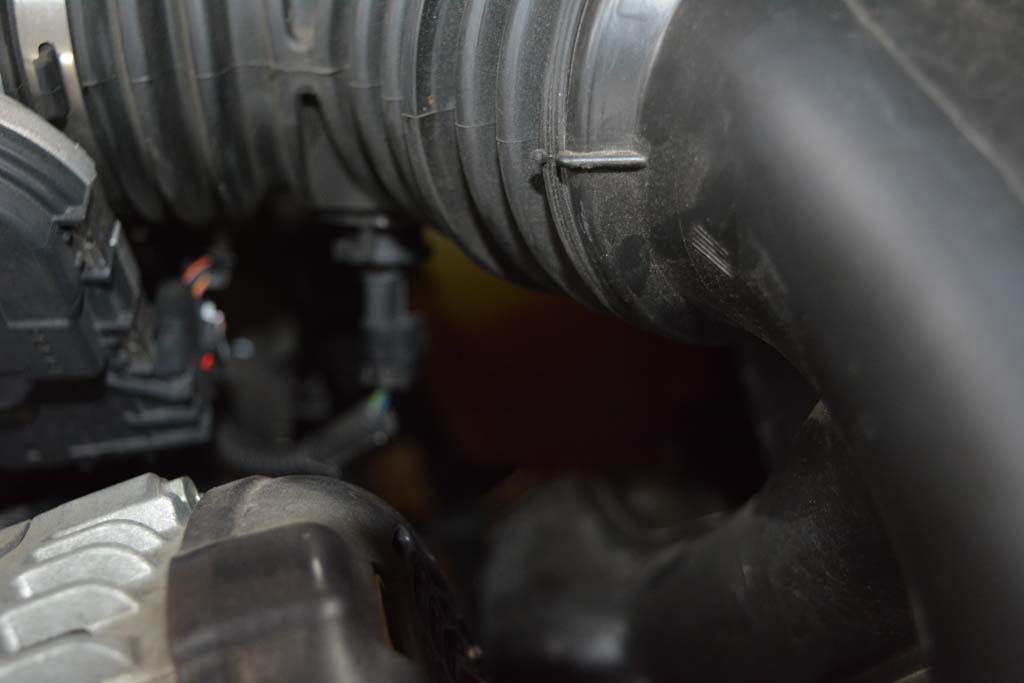
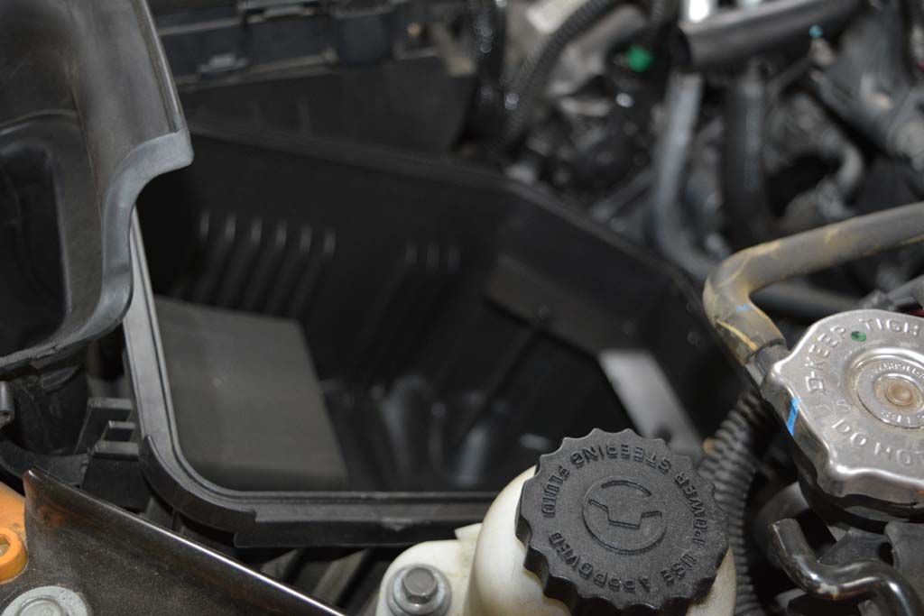
| 6. Remove the lower half of the air box by grabbing at the bottom and pulling up. Make sure the rubber grommets remain in place. These will be reused. |
 |
 |
 |
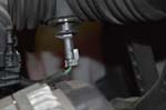
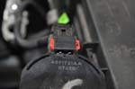
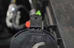
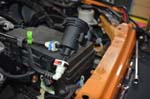
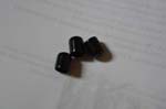
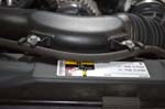
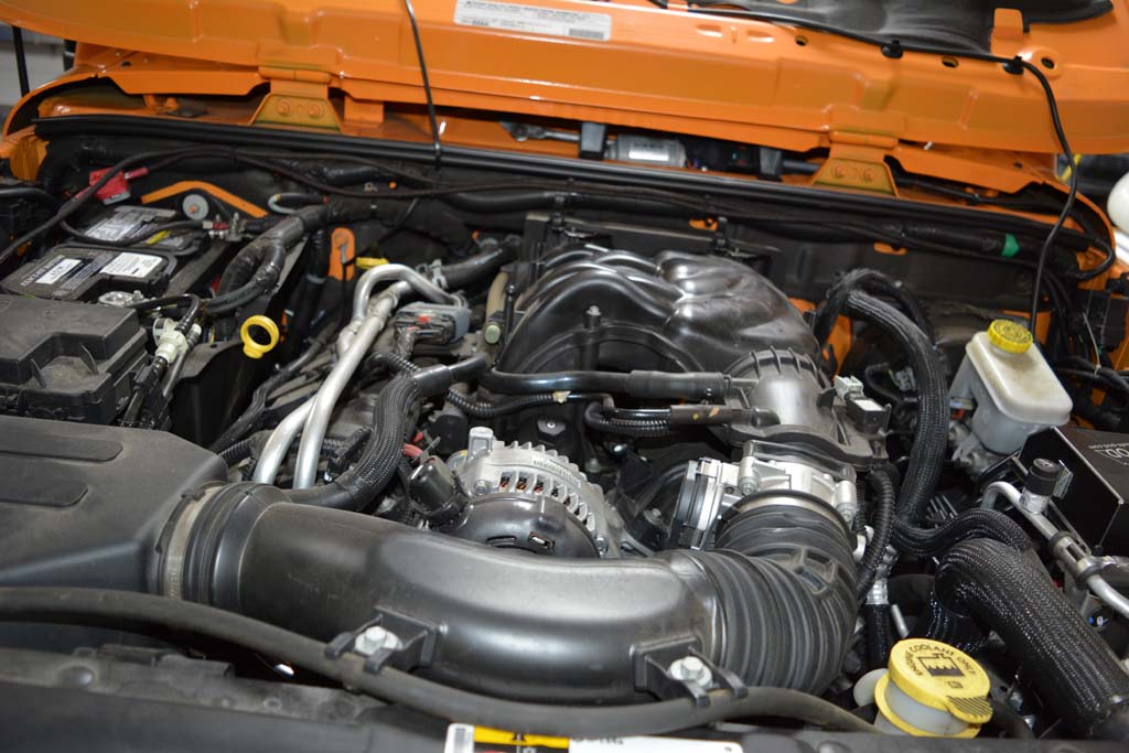
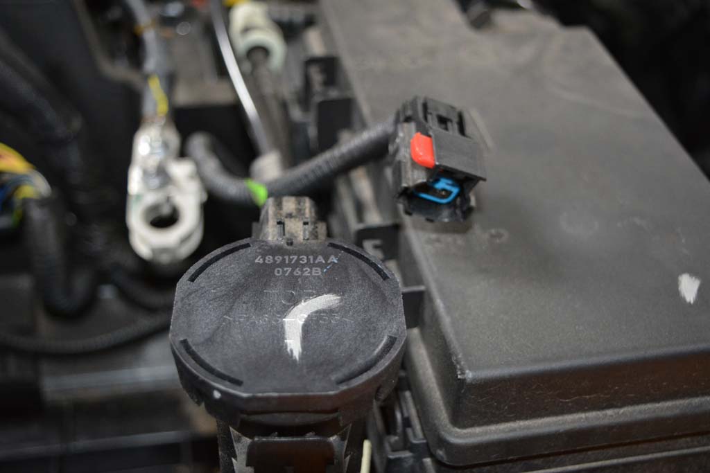
I always seemed to have a weird thump noise from the engine compartment on the Jeep and never really figured it out until I removed the air box. I only have 1 of the 3 prong's still attached. Didn't see them lying anywhere in the engine compartment, or on the garage floor.
|
 |
| |
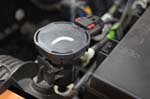
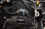
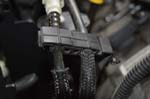
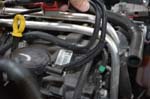
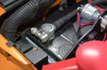
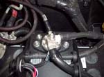
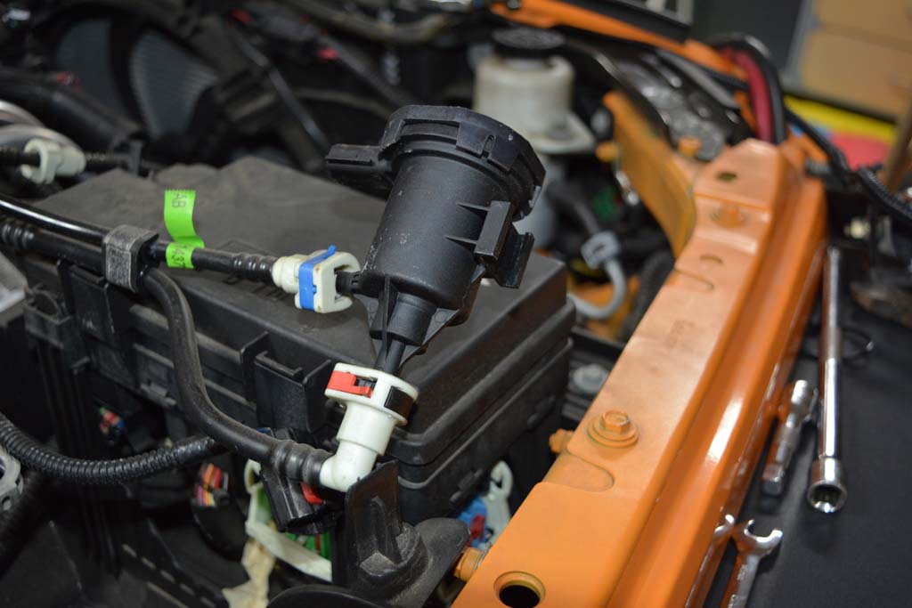
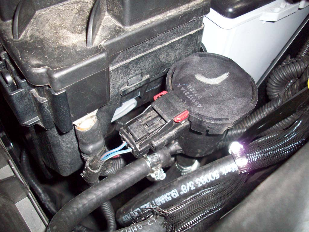
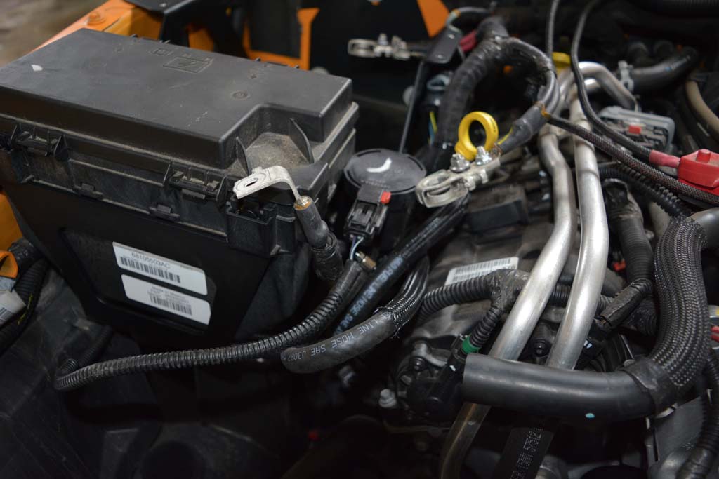
| Purge Solenoid Removal: |
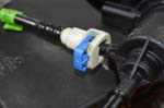
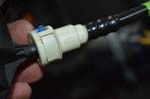
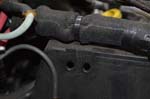
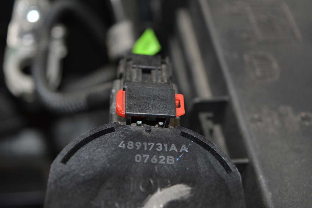
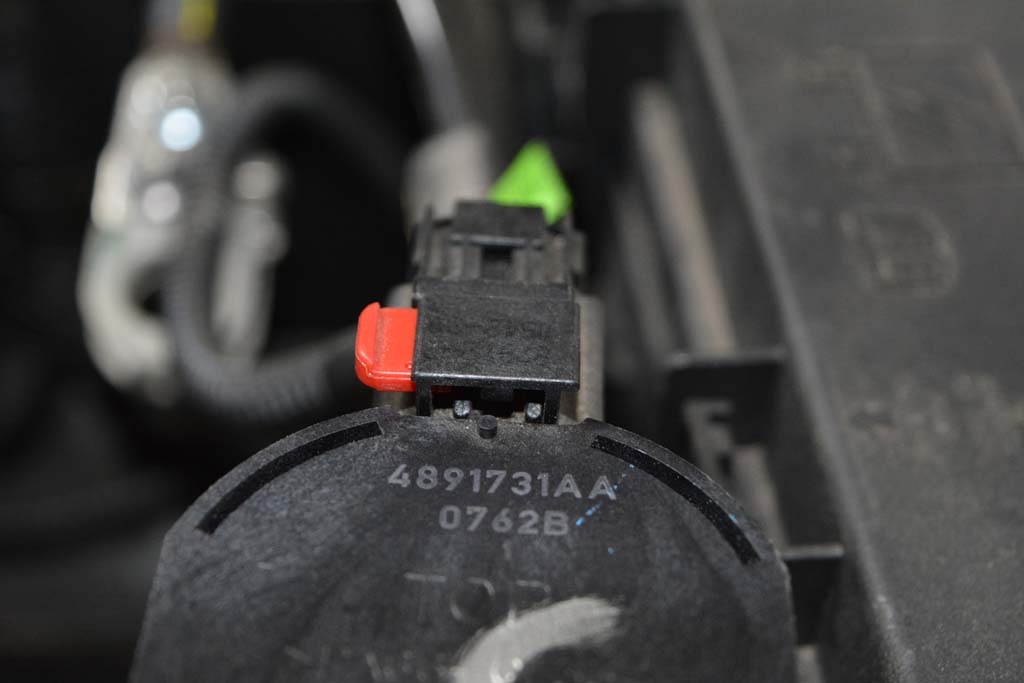
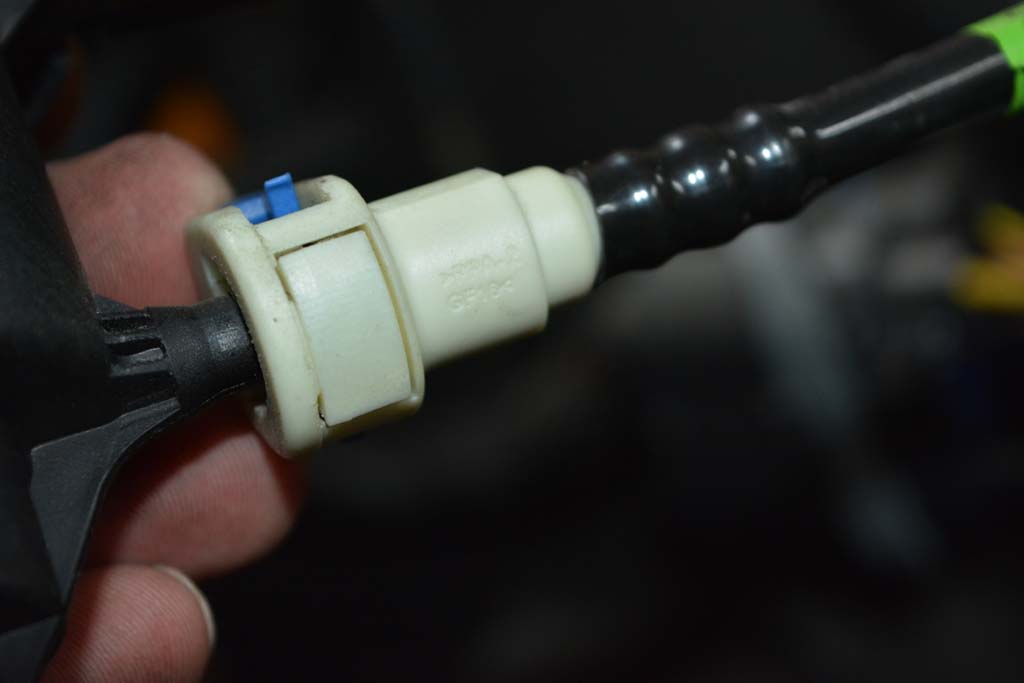
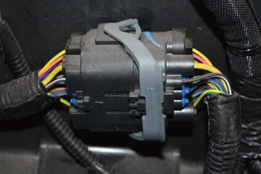
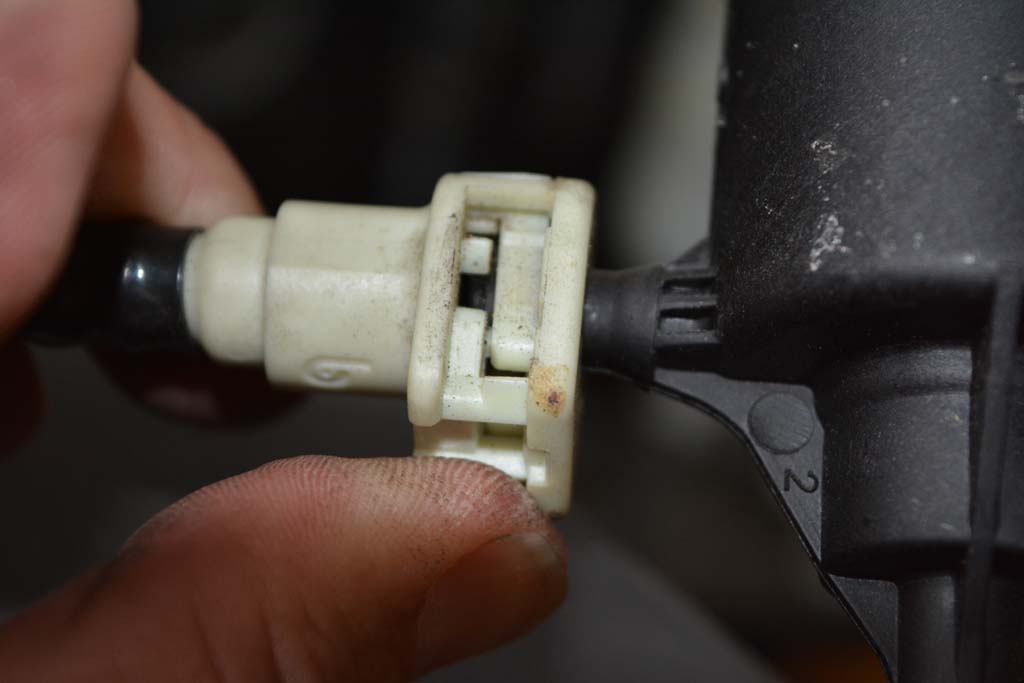
1. Remove the electrical connector by pushing the red tab to the side to unlock it, then push the black tab down and pull to remove it. |
 |
 |
 |
 |
2. Pull up on the solenoid to remove it from its mounting tab. |
 |
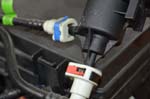
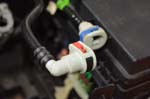
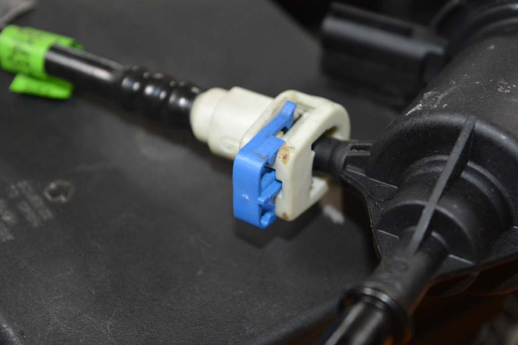
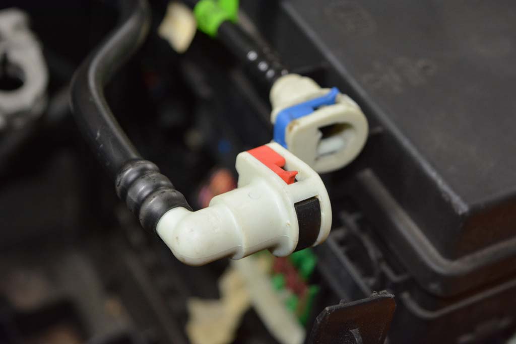
3. Use a small flathead screwdriver to release the red and blue locking tabs on the hoses. |
 |
 |
4. Use both hands to push the hose into the solenoid while you press the black tab. While holding the tab in, pull the hose off the solenoid. Repeat for second hose with the white tab. |
 |
 |
5. Set the solenoid aside. It will be remounted to the new battery tray later |
| |
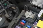
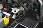
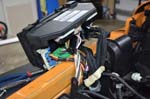
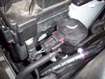
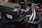
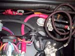
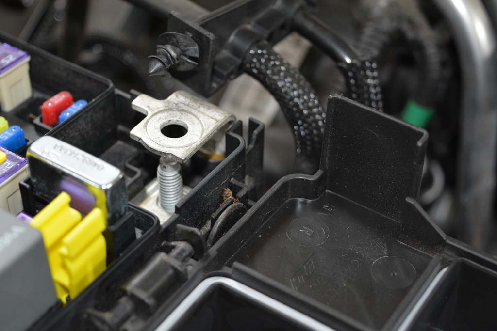
| Moving the Fuse/Relay box out of the way: |
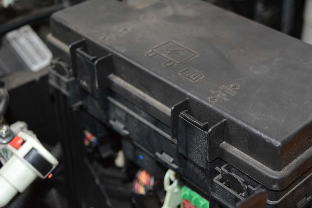
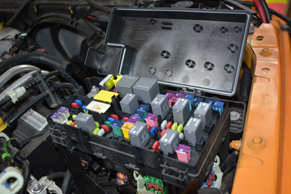
1. Open the lid of the fuse/relay box |
 |
 |
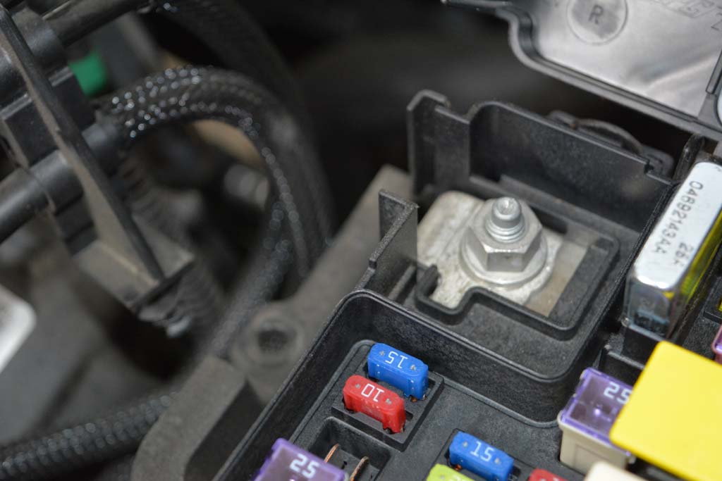
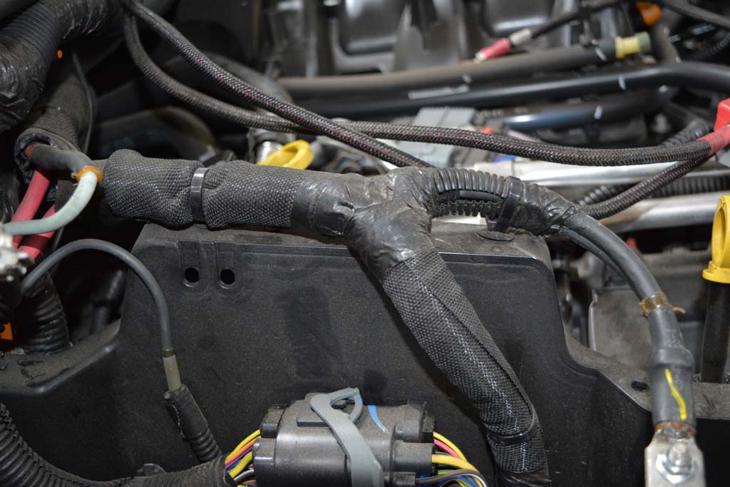
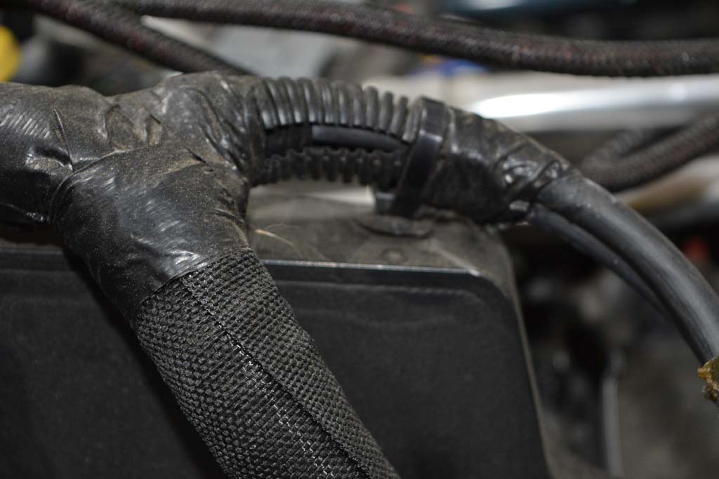
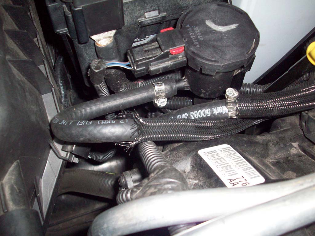
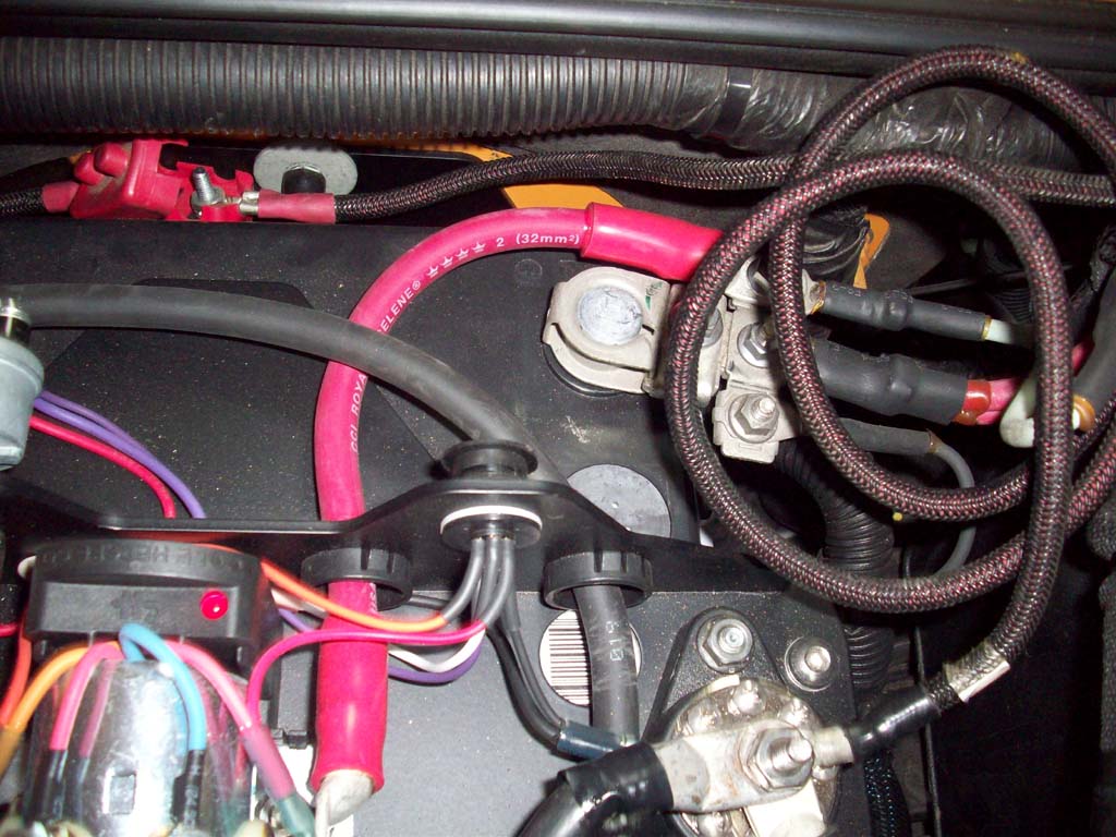
2. Make a note of how the main power feed cable is routed to the fuse box. Your stock wiring harness will be reinstalled in the same orientation. |
 |
3. Use a 13mm socket to remove the main power feed cable. After removing the power cable, reinstall the nut so you don't lose it. |
 |
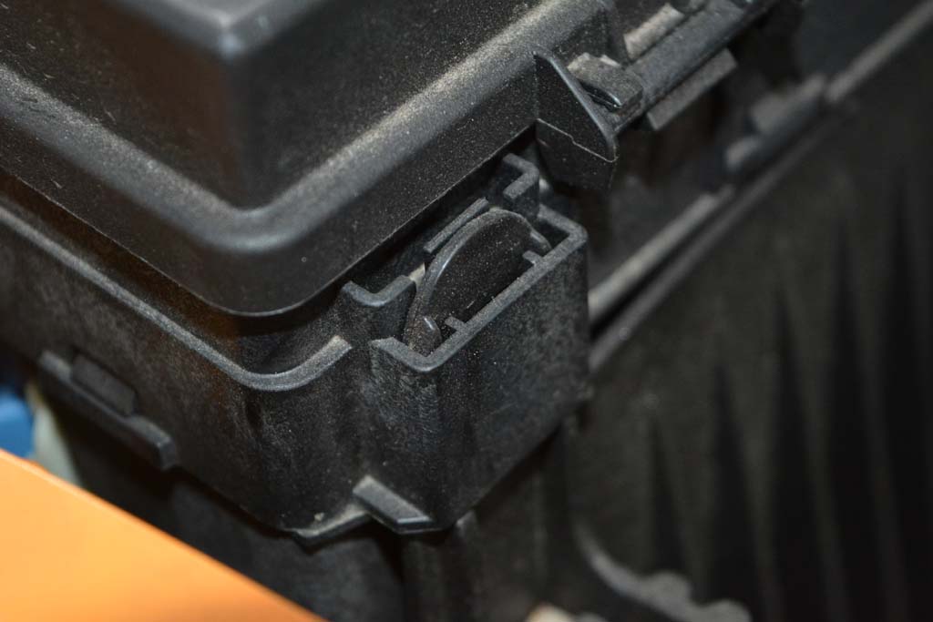
4. Close the fuse/relay box lid. |
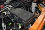 |
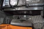
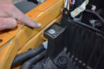
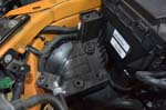
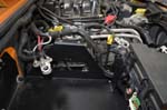
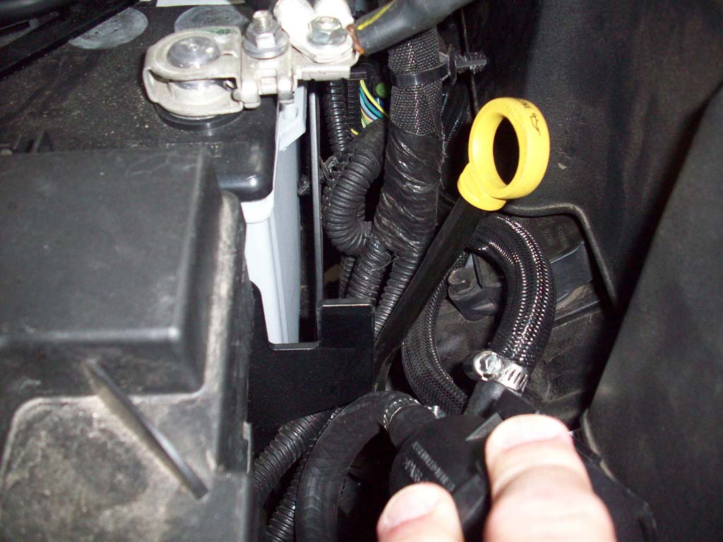
5. There are 4 mounting tabs that secure the fuse/relay box. Use a flathead screwdriver to gently release each of the tabs while lifting the relay box. Keep upward pressure as you work your way around so the tabs don't reattach. |
 |
 |
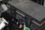
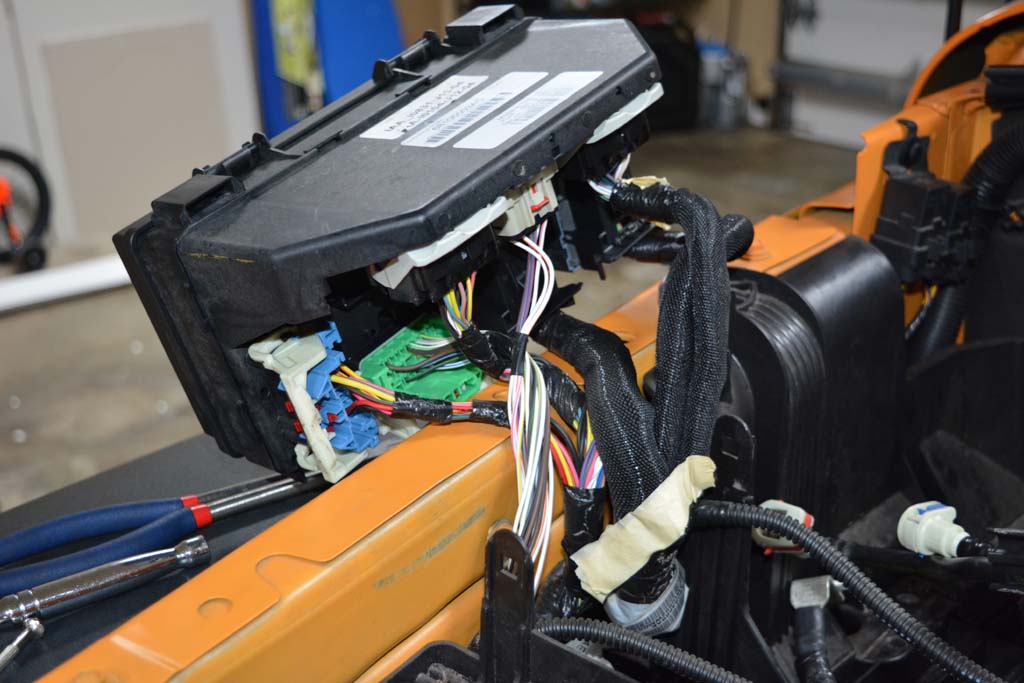
6. At this point, you can attempt to lift the fuse box up and over the side of the fender (be careful not to scratch the fender) with all the connectors still attached. |
 |
 |
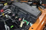
7. If you are not able to get the fuse box out of the way enough to remove the stock battery tray, you can disconnect the connectors on the bottom and remove the fuse box entirely. Set the fuse/relay box out of the way. I thought that I might have to do this, but before you do, just check to see if any of the wires are caught on something preventing the box from moving out of the way. |
| |
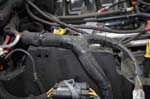
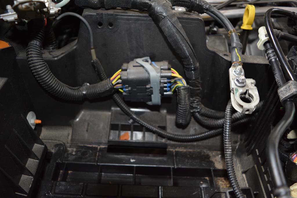
| Disconnecting the wiring from the battery tray: |
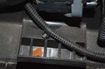
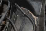
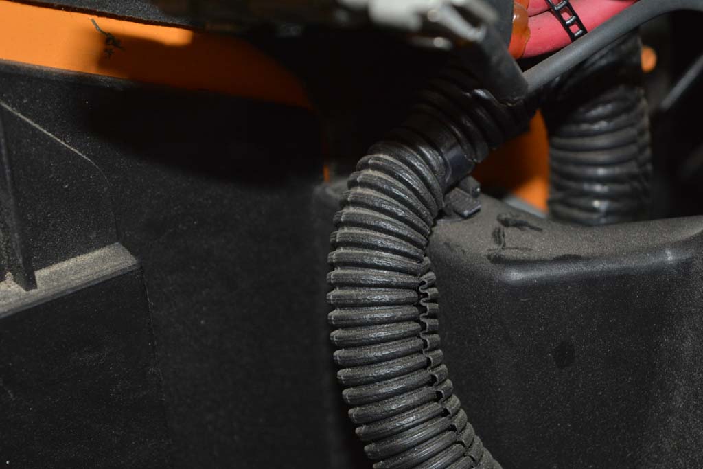
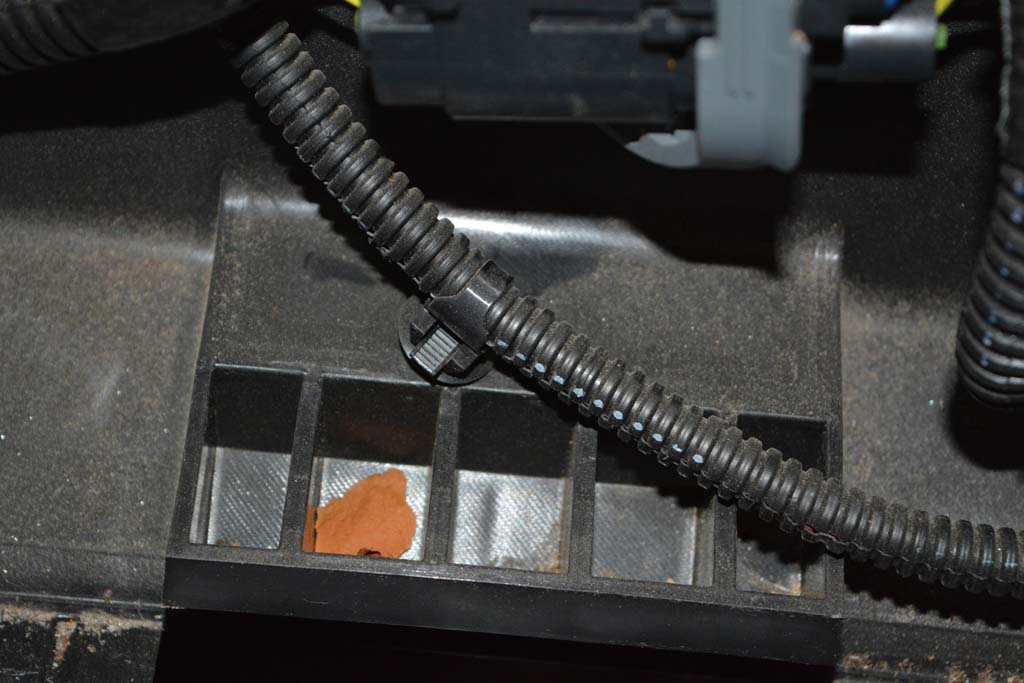
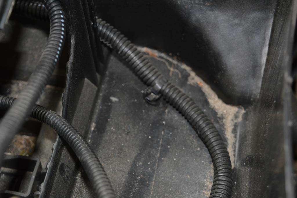
1. Remove all the Christmas tree fasteners that are securing the wiring harness to the side of the factory tray with a small clip removal tool or by gently pulling. Try not to damage these fasteners because you will reattach them to the new tray. |
 |
 |
 |
 |
 |
 |
 |
 |
 |
| |
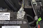
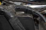
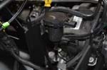
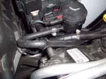
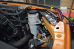
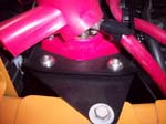
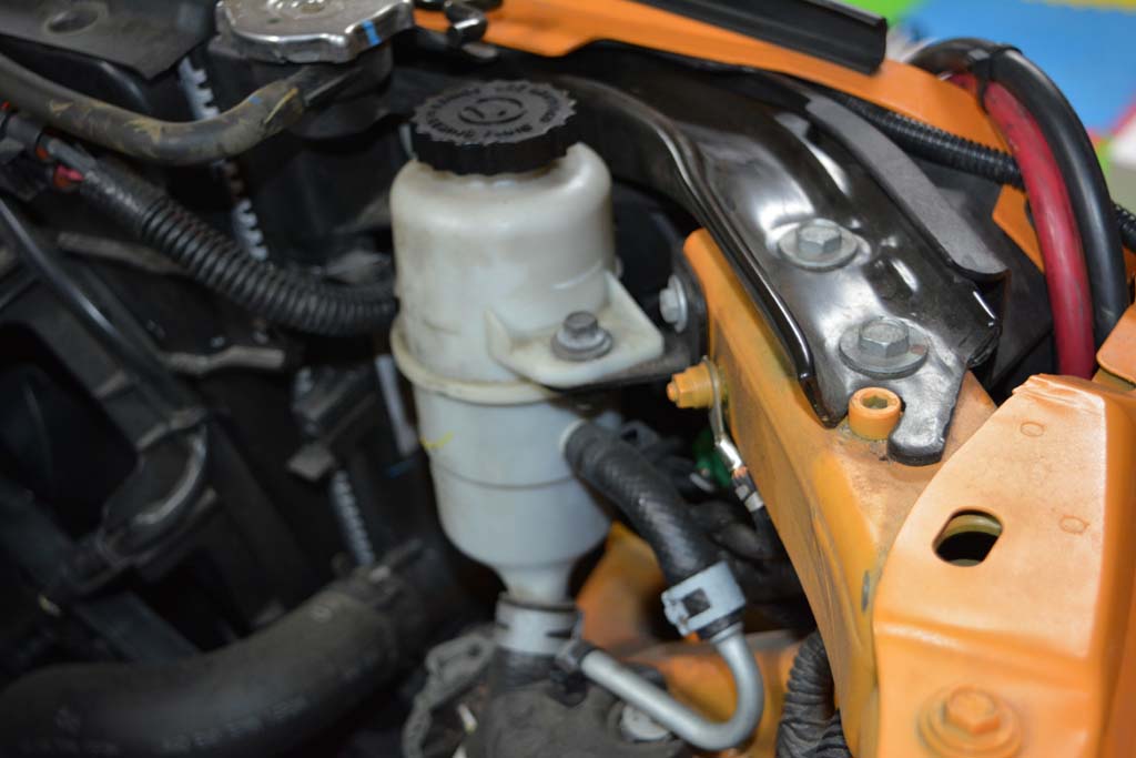
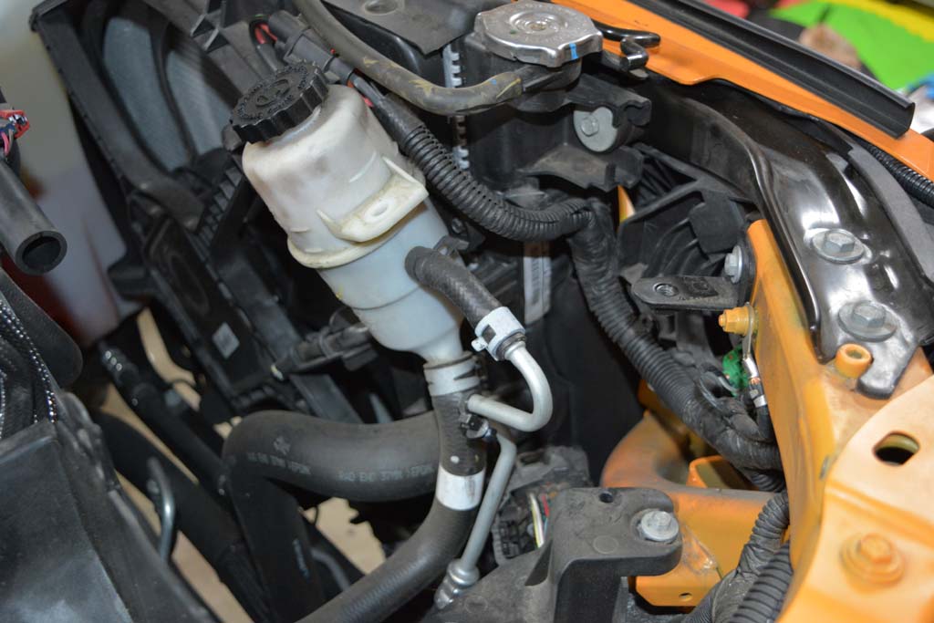
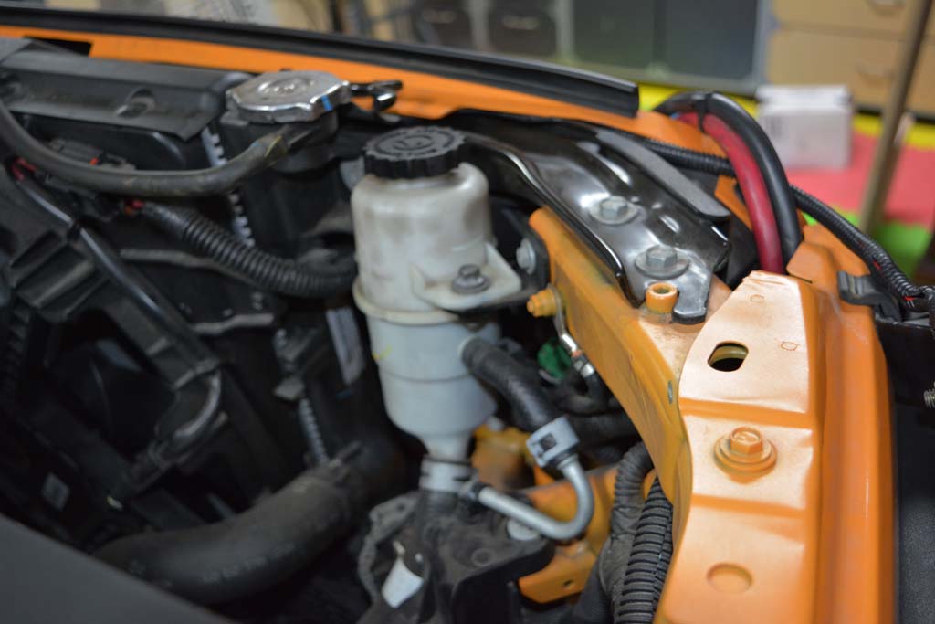
| Power Steering Fluid Bottle Removal: |
Moving the power steering fluid bottle out of the way will make it easier to get the factory tray out. |
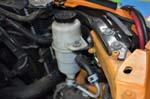 |
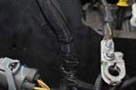
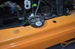
1. Remove the 10mm bolt holding the power steering reservoir. |
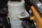 |
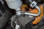
2. Remove the christmas tree securing the hard line by gently prying up. Just move the reservoir out of the way while you remove the battery tray. |
 |
 |
| |
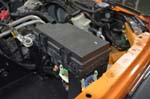
| Battery Tray Removal: |
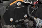
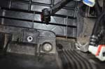
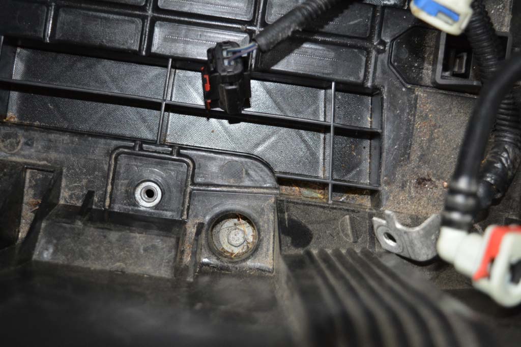
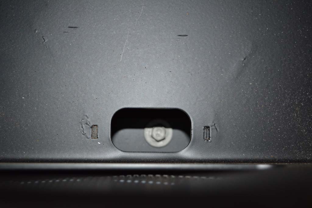
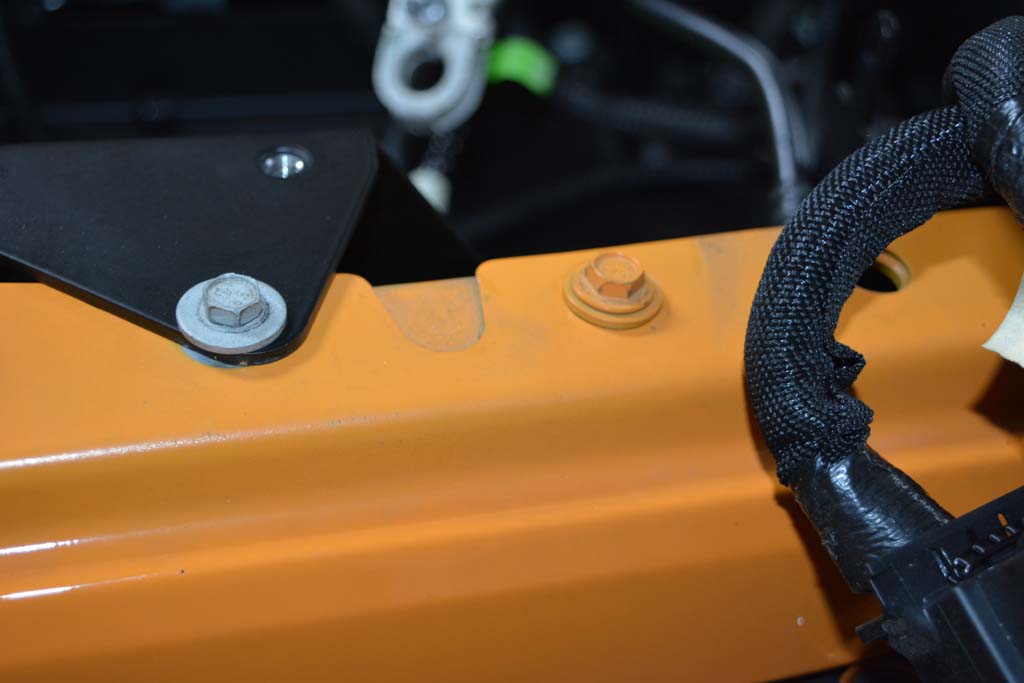
1. Remove one 10mm bolt from the fender well |
 |
2. Remove the 3 10mm nuts from the firewall and 5 10mm bolts as shown. 4 of the bolts are holding the battery tray, the fifth is the fender bolt just in front of the battery tray bolt. |
 |
 |
|
 |
 |
 |
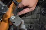
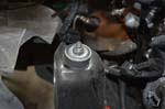
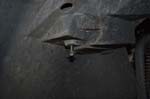
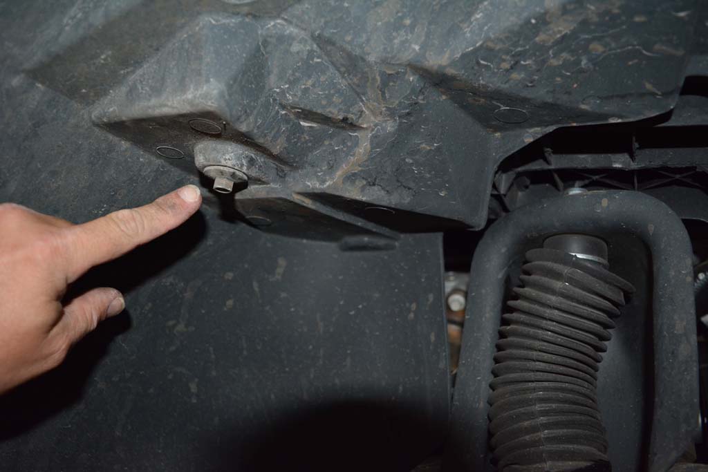
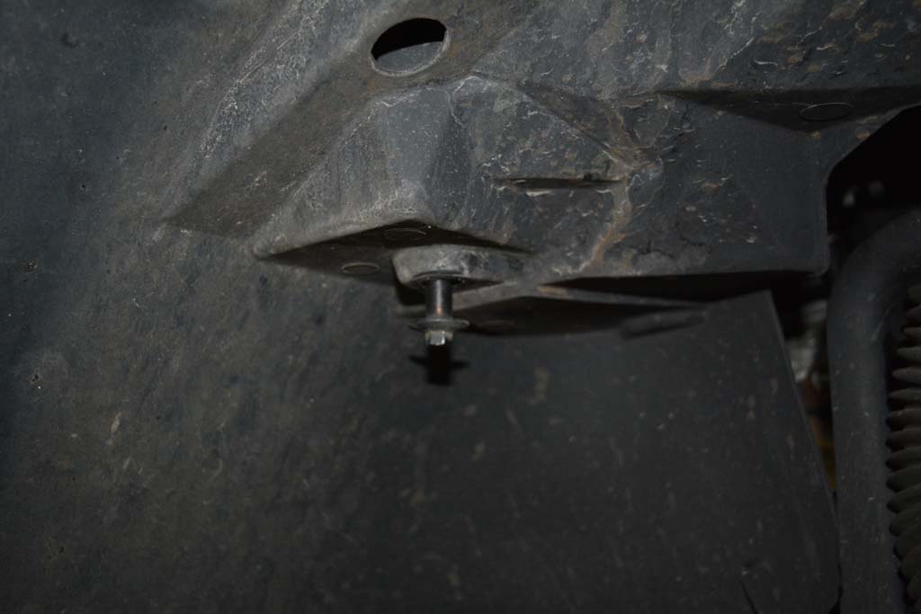
| 3. Pull battery tray out. On some models it is easier to remove the tray by lifting from the front first, others by lifting from the rear first. |
 |
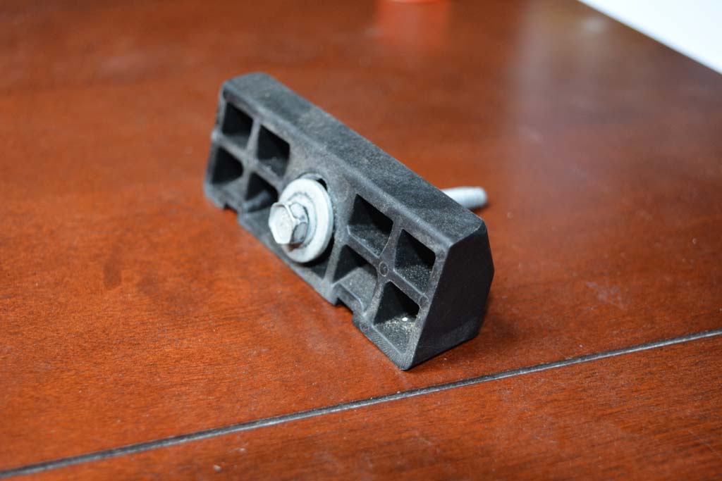
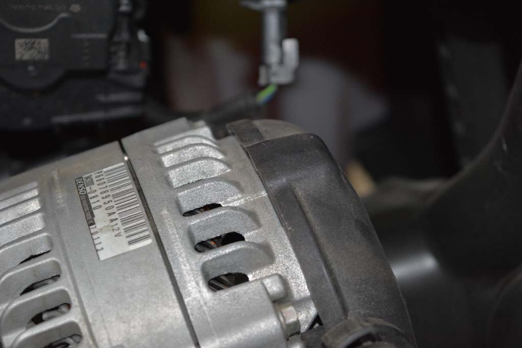
| This is a good time to check that shock nut that is really hard to get to when the battery tray in installed. Mine was a little loose. |
 |
| |
| Battery Tray Installation: |
| Other trays have you cut the insulation away on the firewall to install them. The Genesis tray fits perfectly fine over the insulation, but if you want to cut it you can. |
|
 |
 |
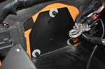
1. Install the new battery tray just like the factory tray came out. |
|
|
|
2. Align with the bolts on the firewall |
|
|
|
3. Reinstall the factory nuts onto the firewall. |
|
|
|
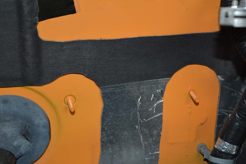
4. Use a cutoff wheel to cut the excess threads flush with the nuts as shown below. |
 |
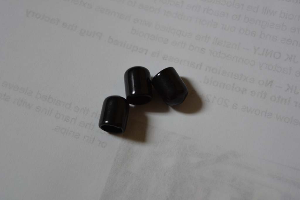
5. Place the plastic caps over the cut off threads on the firewall. This will protect your batteries from being scratched. |
 |
 |
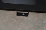
6. Loosely reinstall the lower fender bolts as shown. Tighten the firewall nuts first, and then tighten the fender bolts. Due to slight manufacturing variations on the fender and brackets, it is easiest to get all the bolts in loosely so the tray can be moved around to get all of them lined up. It will fit. |
 |
 |
 |
| |
| |
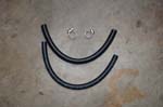
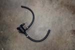
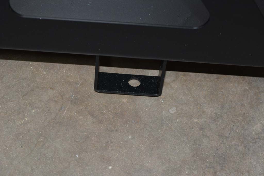
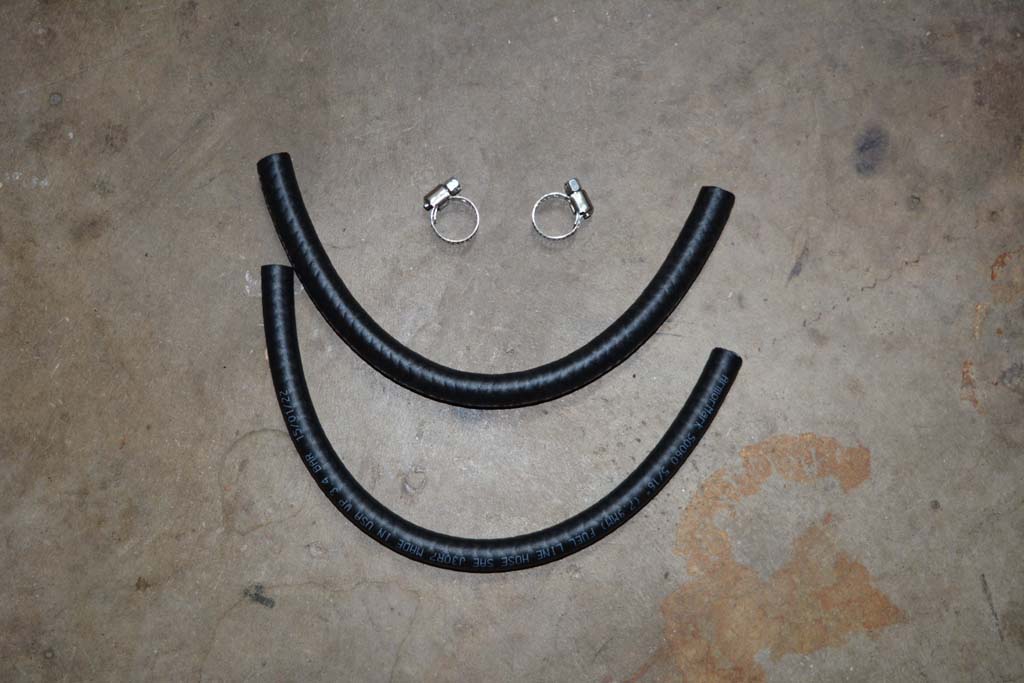
The evap solenoid will be relocated to a tab on the tray. The factory molded plastic lines are designed to reach the factory mounting location. You will cut the hard plastic lines and add our short rubber hose to reconnect the solenoid. |
 |
 |
 |
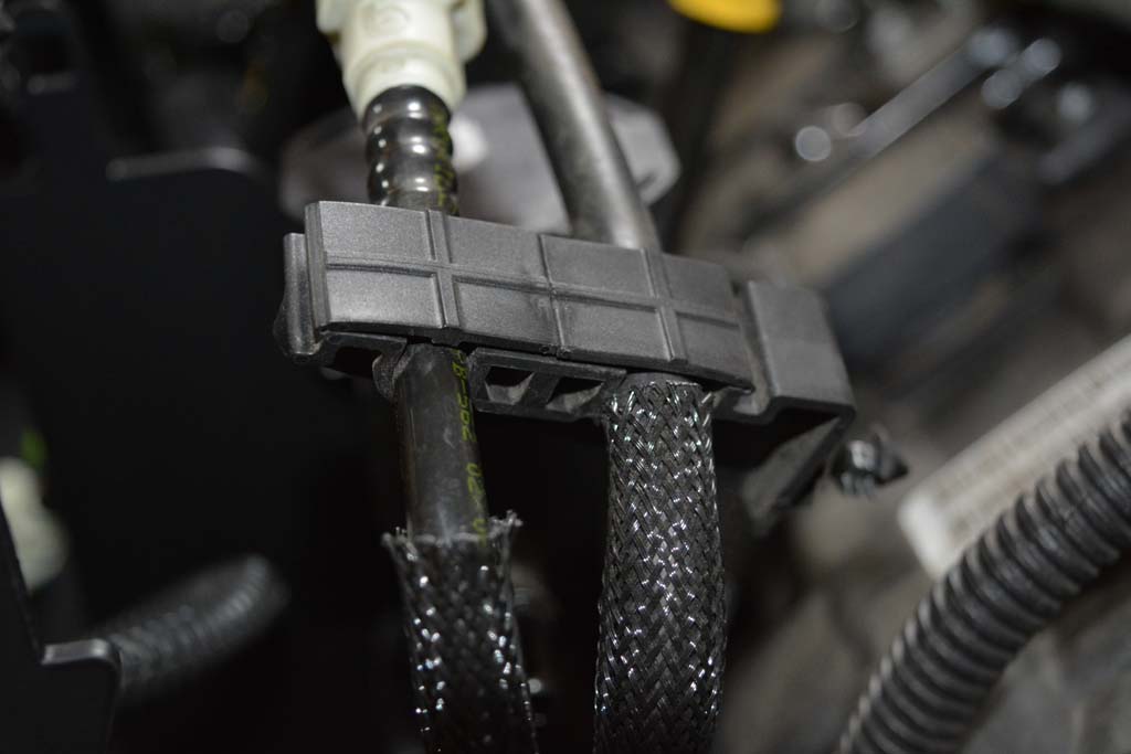
| Remove the plastic holder from the evap lines. It makes it easier to cut the lines later. I pried it apart with a flat tip screwdriver. You don't have to do this if you don't want to. |
 |
 |
FOR '07-11 JK ONLY – Install the supplied wire harness extension cable between the factory connector and the solenoid. |
FOR '12+ JK – No extension harness is required. Plug the factory connector into the solenoid. |
 |
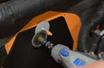
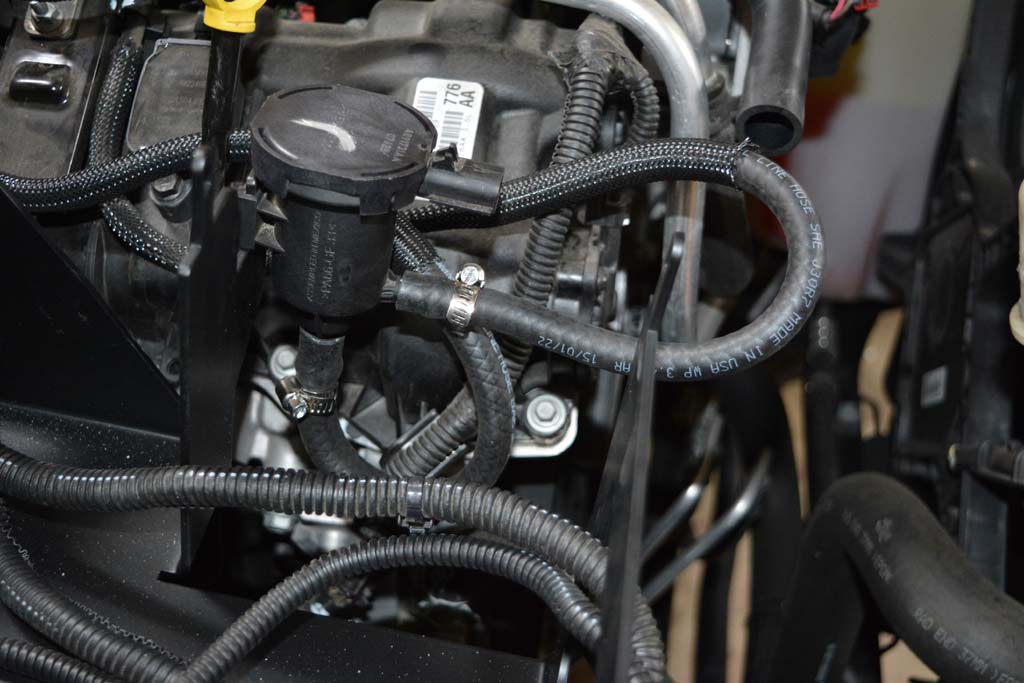
For the 2012+ 3.6L. Push the braided sleeve back and cut the hard line with strong scissors or tin snips. |
 |
|
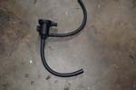
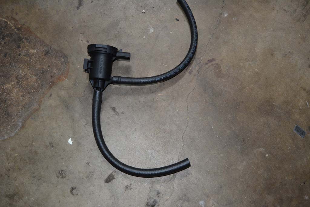
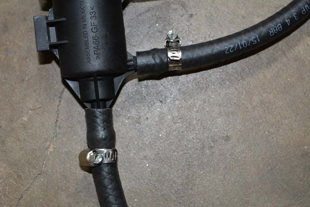
Here you see the hard lines cut, and the new fuel hose attached to the evap solenoid. Use the hose clamps included with the kit to secure the fuel hose to the evap solenoid. It's alot easier to install the hoses with the solenoid removed from the vehicle. |
 |
 |
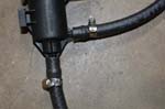 |
Push the new fuel hose onto the hard lines as far as they will go, then push the braided line down over the new fuel hose. |
 |
You do not need a hose clamp on this end because the hard line will make a tight fit inside the new fuel hose.
Note: I had a code thrown a few weeks later saying I had a small leak in the evap system. I ended up tracking it down to the hose going to the evap line from the purge solenoid. I was able to move the line, so I knew that it wasn't sealing well. A small hose clamp fixed this problem. |
 |
 |
You will need to check the instructions for the 2007-11 3.8L engine, to show the approximate location to cut the hard lines. |
TIP: To find the best place to cut the lines, attach the new fuel lines to the evap solenoid, place the evap solenoid on the tab on the battery tray, then hold the fuel lines up to see where they line up with the factory hard lines. Make sure the fuel hose does not have any kinks or interference with other components. Mark a spot on the hard lines where the new fuel line will overlap slightly. |
| |
| |
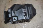
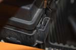
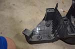
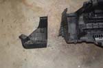
Cut off the air box mount from the rest of the tray. Just follow the rib line. I used a saws all with a long blade and just cut down along the side of the box, so my ribs still stick out. |
 |
 |
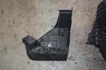 |
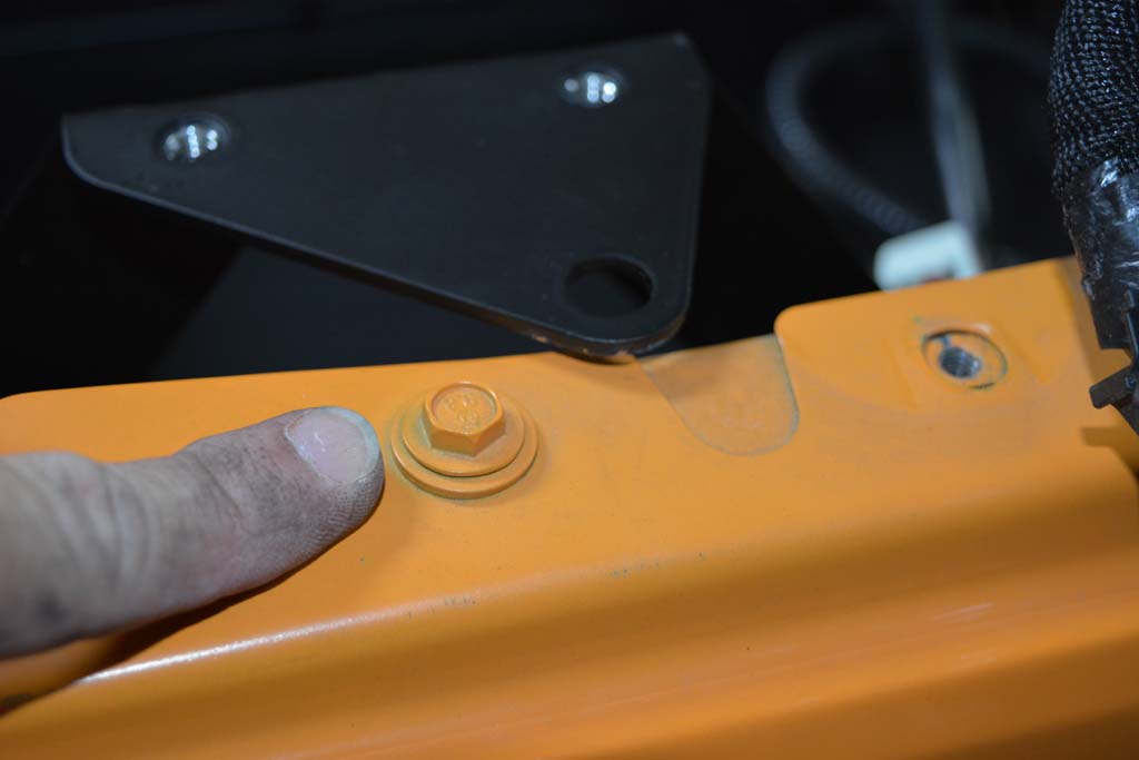
| 1. Install the cutoff section of the air box mount using 2 10mm factory bolts. |
 |
2. Reinstall the power steering reservoir onto its bracket with 1 10mm bolt. |
 |
3. Reinstall lower section of the air box by pushing down until it snaps into the rubber grommets. |
 |
4. Reinstall air filter and top cover, and then tighten the hose clamp on the intake tube. |
 |
 |
 |
5. Reinstall the crankcase vent tube onto the side of the air box cover. |
 |
| Reinstall the connector for the IAT sensor on the intake tube. |
 |
6. Reinstall the 2 10mm bolts that secure the air intake tube to the top of the radiator. |
 |
| |
| |
1. Slide the fuse/relay box down onto the mounting tabs. |
 |
2. Reconnect the main power feed cable inside the fuse box using the factory 13mm nut. |
 |
 |
 |
| |
| |
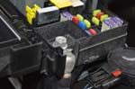
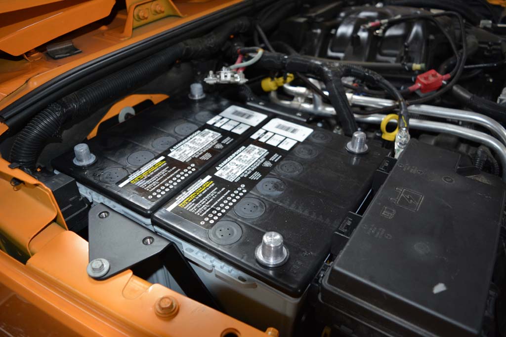
1. Leave the plastic covers on your battery posts for safety. Mine came with a plastic box over the top, so I had to discard it to get the batteries installed and continue on. Just be very careful around the terminals. |
2. Install your cranking battery with posts towards the firewall. Make sure the positive terminal is toward the engine side and the negative terminal is toward the fender side. |
 |
3. Install your accessory battery with posts towards the front as shown. |
| |
| |
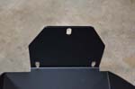
1. Make sure the posts are still covered to prevent shorting the batteries, then lower the top mount plate over the batteries. Be careful if you have uncovered terminals like I did. |
 |
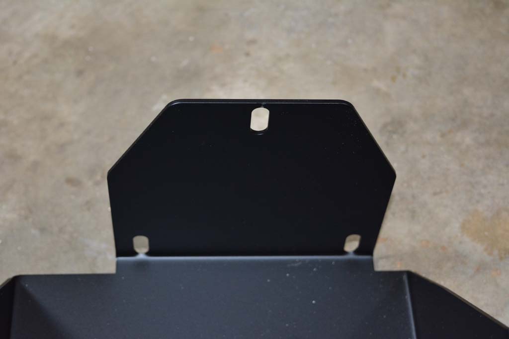
NOTE: If using Optima batteries, the top lid has 4 round cut-outs that line up with the raised circles on the batteries. Be sure the top lid is sitting flush against the top of the batteries. You can see the two holes to the right in the picture. |
|
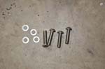
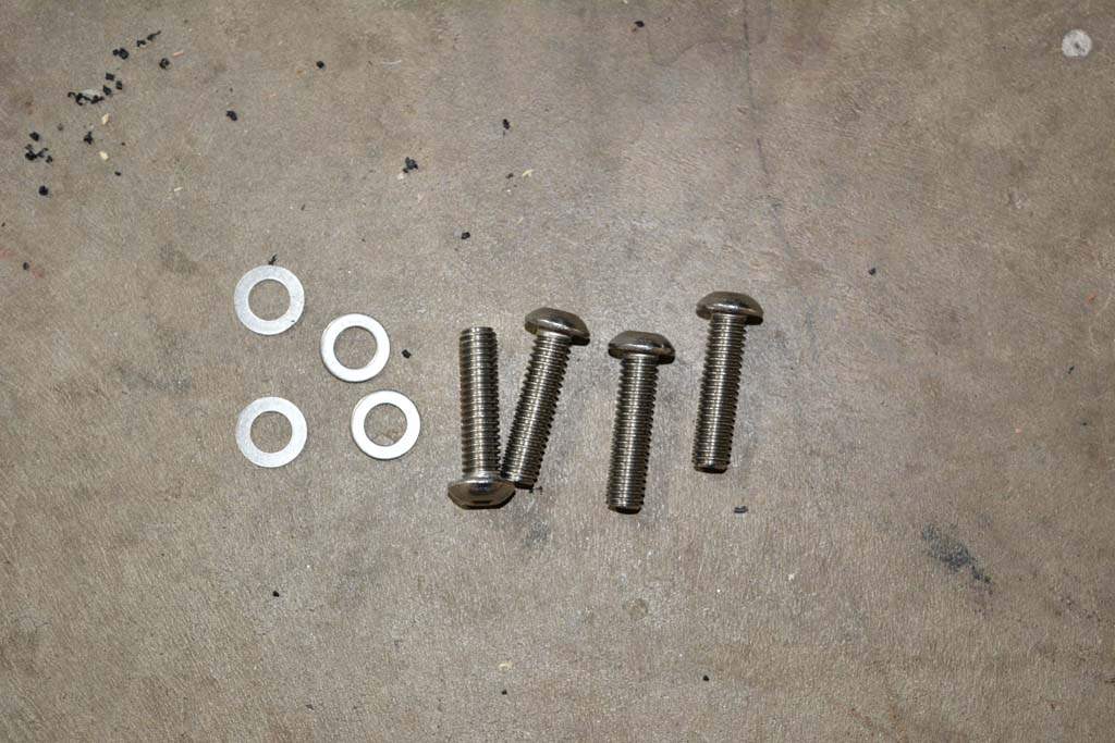
2. Secure the top plate with 4 included stainless steel bolts, lock washers, and nuts. You want it very snug, but do not over tighten to the point of bending the top plate. |
 |
 |
 |
NOTE: There may be a GAP between the top plate and the main battery tray. Optima batteries are slightly shorter than Odyssey batteries. This gap allows you to get the bolts very snug and leaves tension on the nuts. |
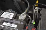
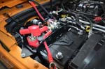
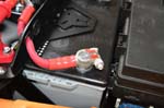
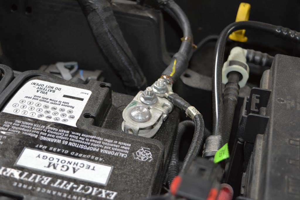
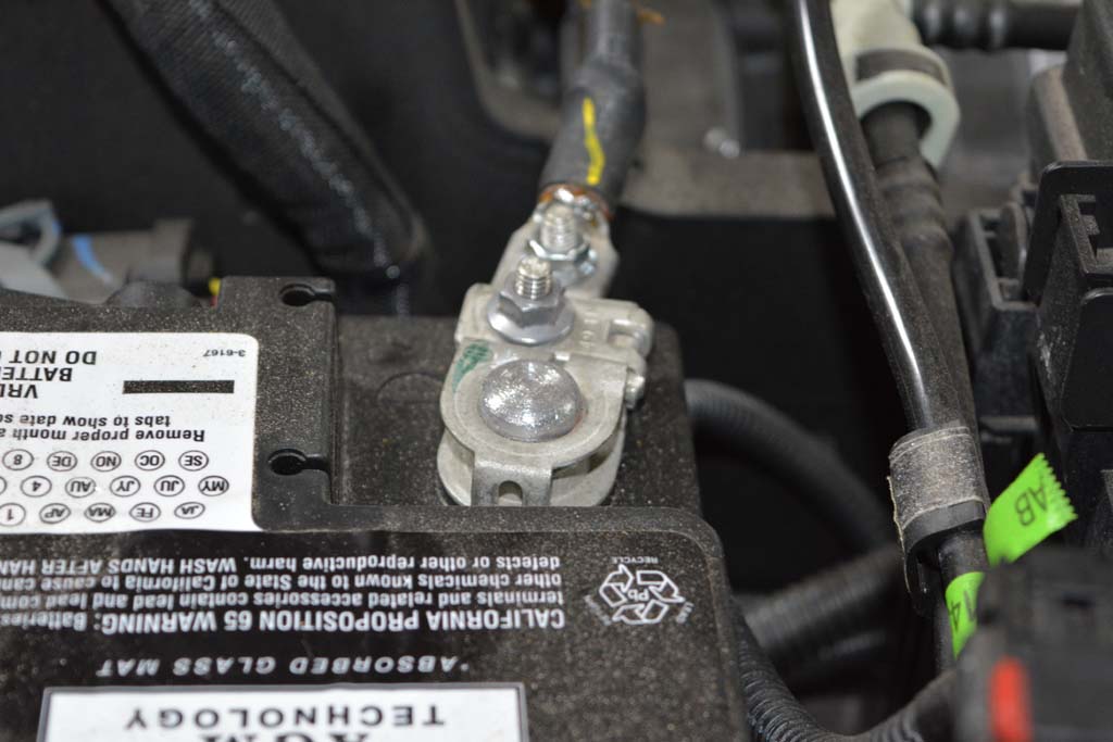
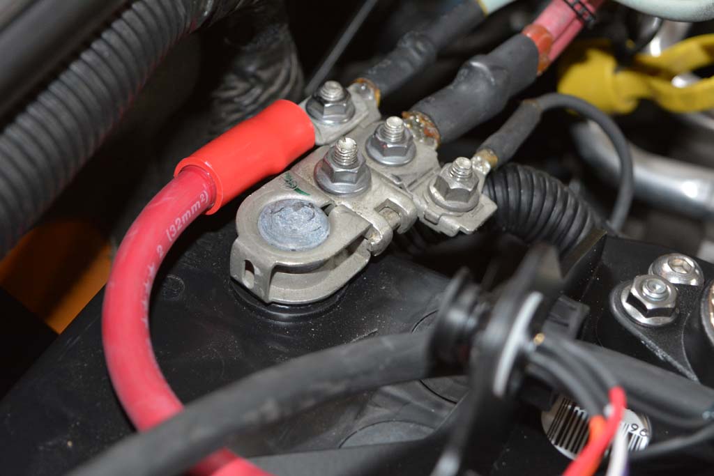
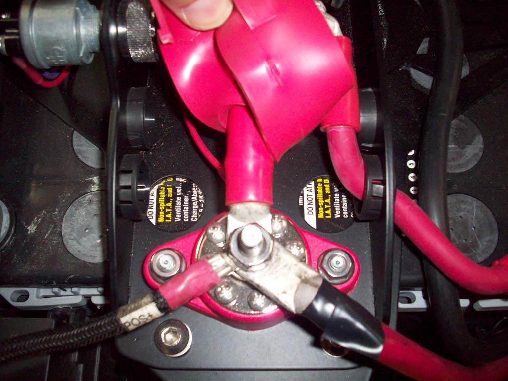
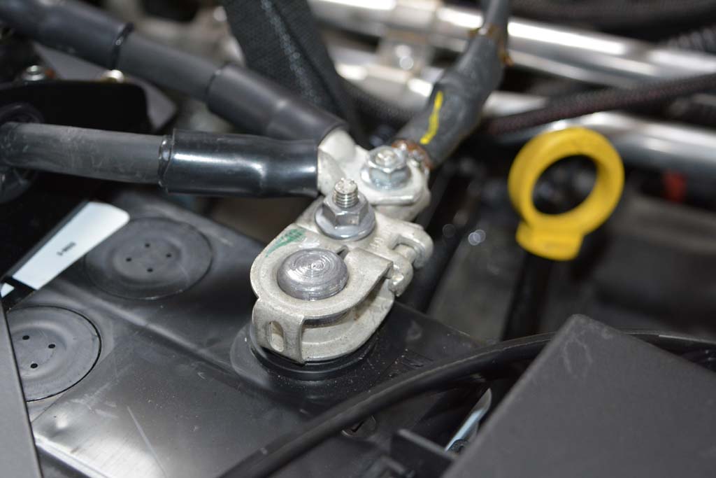
3. Attach the factory positive terminal to the cranking battery by the firewall. Tighten the 10mm nut on the post clamp. |
 |
4. Remove the 10mm nut on the factory positive lead closest to the firewall, and attach the red lead from the smart isolator, then reinstall the nut. |
 |
 |
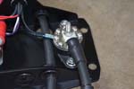
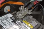
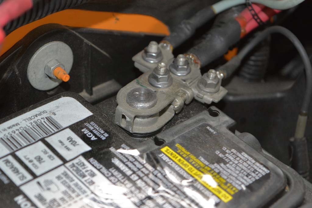
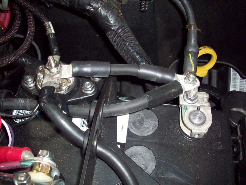
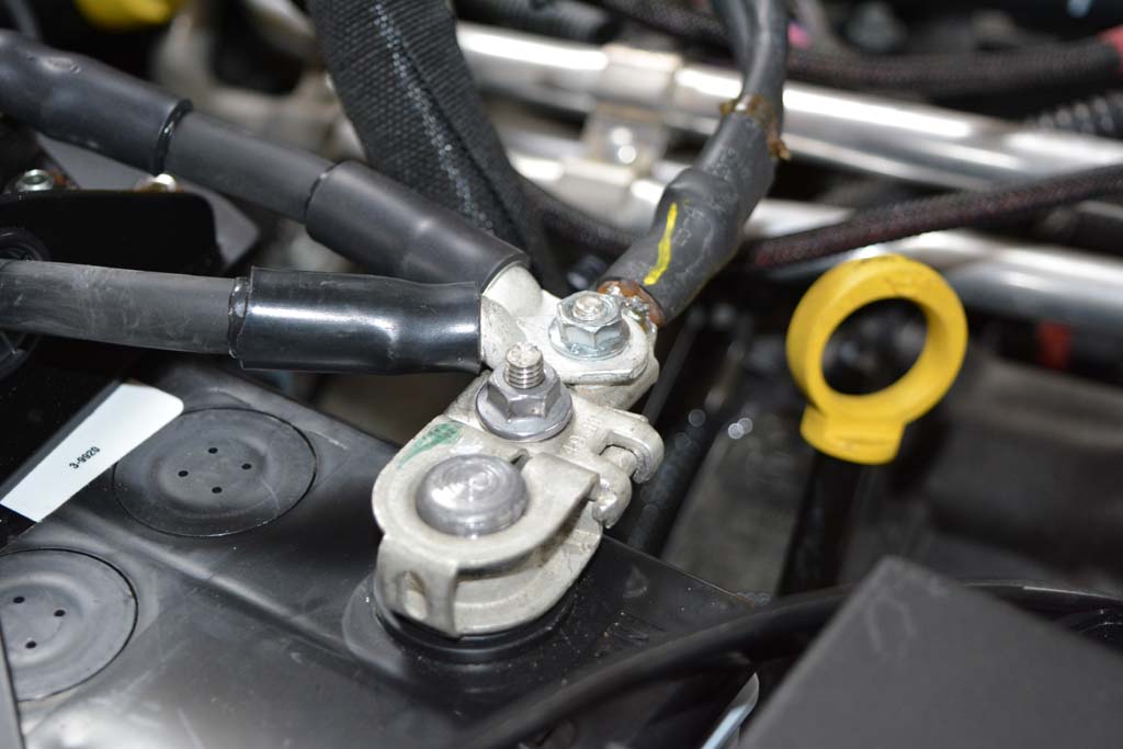
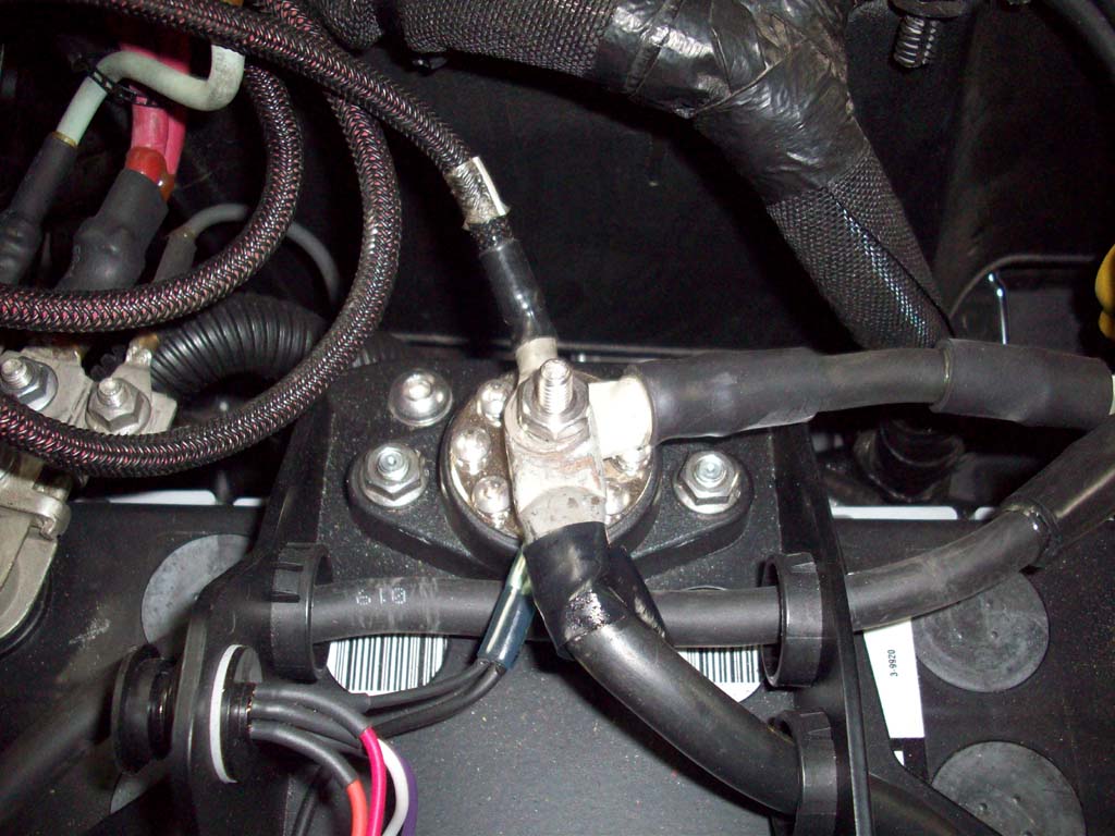
5. Remove the plastic cover from the accessory battery negative post. Attach the factory negative terminal connector to the accessory battery. Remove 10mm nut from factory negative wire lead and attach the ring terminal from the negative wire lead. Stack the lead from the ground bus bar, and tighten the nut securely. |
 |
 |
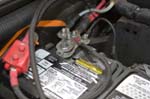
6. Attach post clamps to the cranking battery negative and the accessory battery positive posts. |
 |
 |
|
| |
1. Reinstall engine cover. |
 |
2. Double check all wires and hoses are properly secured. |
3. Start the Jeep. |
NOTE: If the Jeep won't start, or you have any unusual symptoms, check all the connectors on the bottom of the fuse box. Removing and reseating the connectors normally clears any issues. |
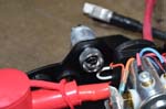
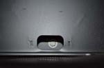
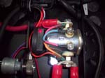
4. Check the status indicator light on top of the smart isolator. Once the smart isolator detects the cranking battery is at 13.2 volts, the red LED light will come on, indicating the batteries are fully charged and connected. Brand new batteries may need to charge from the alternator for several minutes before the indicator light comes on. This is normal. |
 |
| 5. Install any accessories to the terminal blocks. |
 |
 |


