At 80,000 miles on the Jeep JK running 35" tires with a 4.5" backspaced wheel I hadn't shown or didn't realize I had any issues with the OEM ball joints on the JK. Even though I hadn't seen any problems with the OEM ball joints I decided that at 80k miles it was definetly time to move up to something a little stronger and to give myself a little more piece of mind that I wouldn't have a ball joint issue in the near future. What I discovered when I pulled the steering knuckles off surprised me and the difference in the drive afterwards made me realize a few other signs that I didn't think of. I decided to replace the ball joints with Teraflex's Dana 30/44 HD Ball Joints. All the replacement ball joints that I looked at were very similar in construction, options, adjustablity and for a few price point. The main reason for me deciding on Teraflex was that I had always enjoyed their great customer service. The honesty and knowledge of their service department is awesome. Not only do these ball joints have a lifetime-guarantee, but they are adjustable as the wear. All you need to do is loosen 3 set screws and use the spanner that Teraflex provides to tighten up the load on the ball joint. This is important because all the weight is carried by the lower ball joint. The upper joints use a wear-resistant sintered metal bushing while teh bottom has a large hard alloy tool steel wear plate. The ball joints are greaseable without having to remove a shaft to get at the zerk fittings. They do make the same ball joints in a knurled version if the mounting holes have loosened up on the axle.
| Parts: |
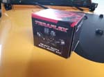
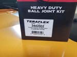
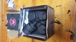
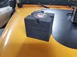
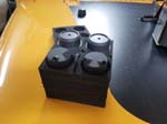
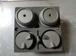
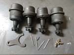
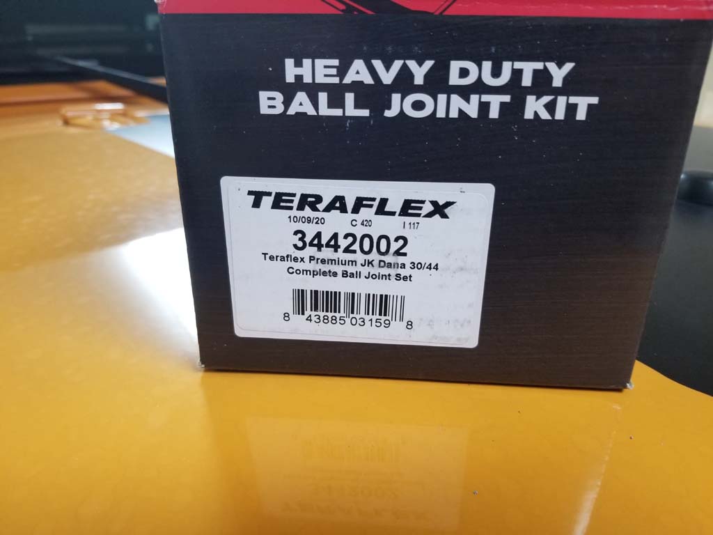
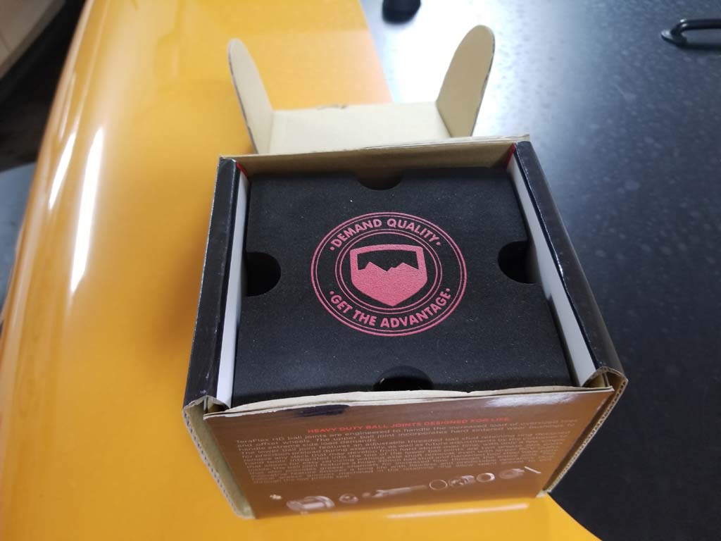
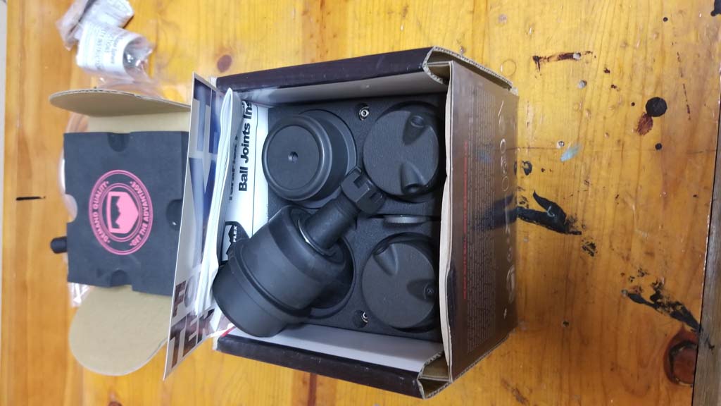
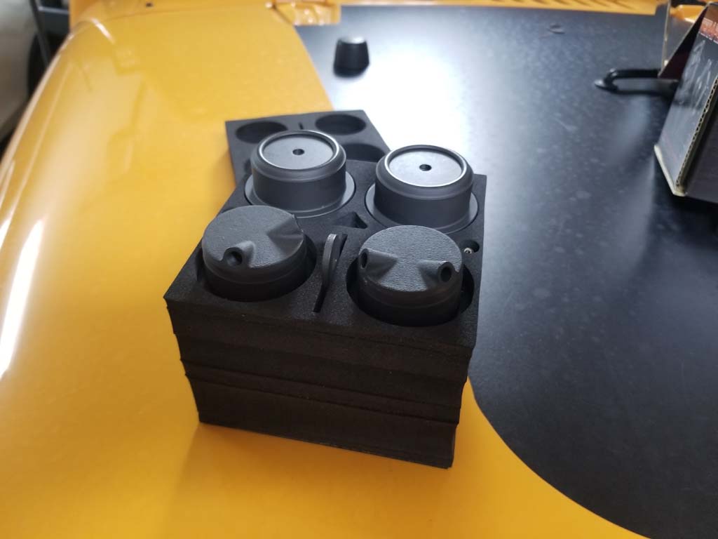
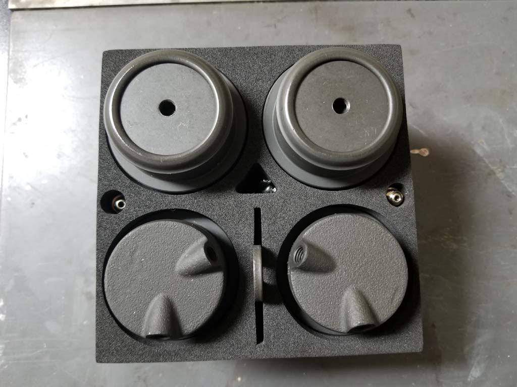
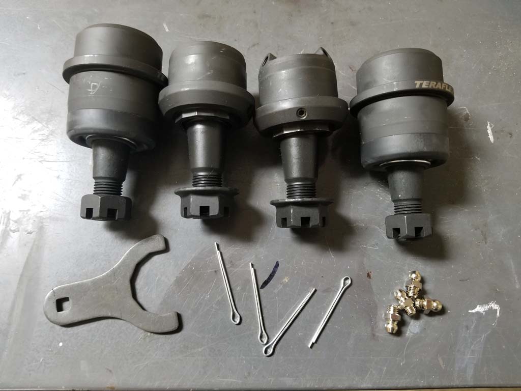
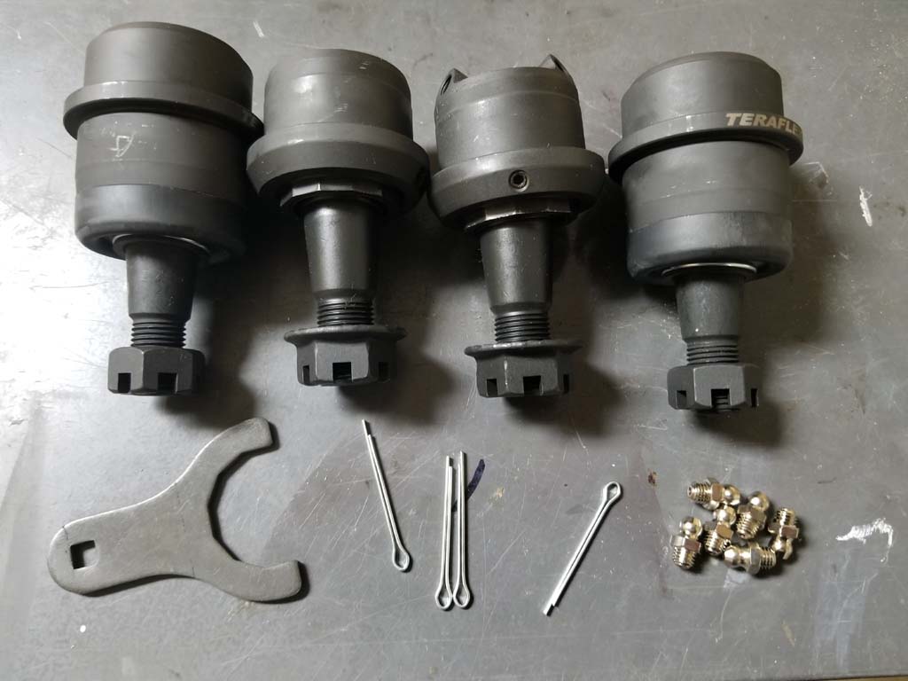
| Teraflex out did themselves on the packaging of these ball joints. Once you open the box you find a dense foam container inside. The joints and all the parts are enclosed in dense foam for protection. The hardest items to get out of the foam are the zerk fittings. I ended up using a tweezers to pull them out of the holes on either side of the foam box. The kit comes with 2 upper ball joints, 2 lower ball joints 4 cotter pins, 6 zerk fittings and an adjustment spanner. |
 |
 |
 |
 |
 |
 |
 |
 |
| |
| Disassembly: |
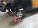
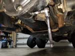
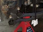
| 1. Jack up the front axle and support it with jack stands. Remove the front wheels. This install starts on the passenger side of the Jeep. |
 |
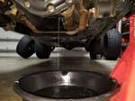
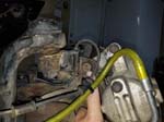
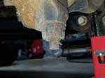
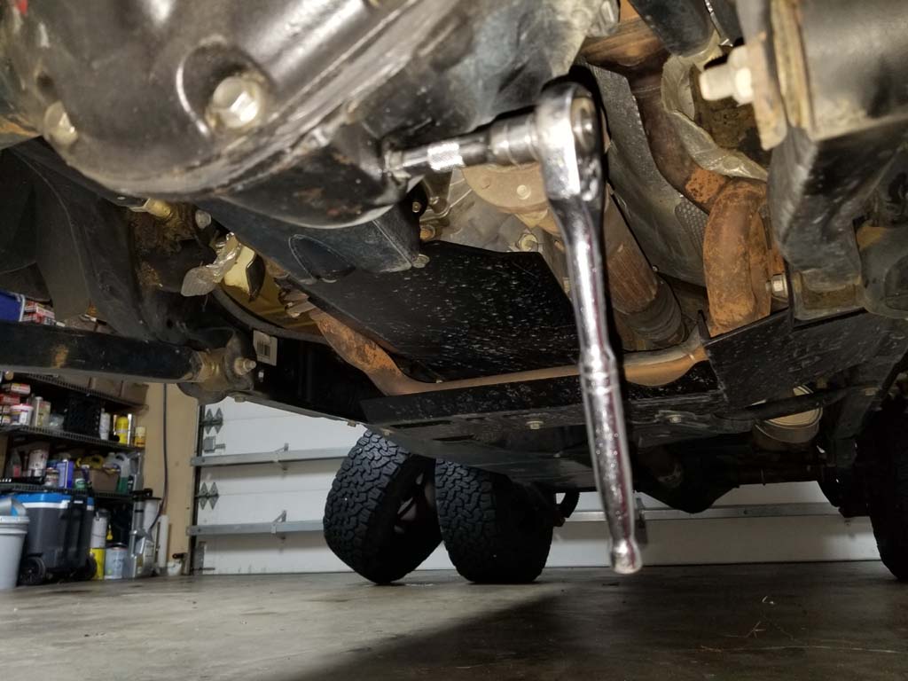
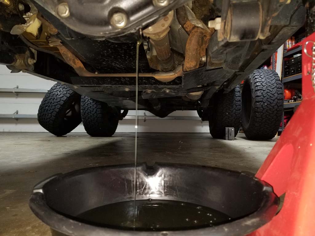
| 2. Drain the oil from the front axle. I have the Dana 44 axles so there is a convient drain plug on the bottom side. Use a 3/8" ratchet and short extension to remove the plug. I changed out the diff fluid at the same time, but with a clean drip pan you could reuse the oil in a pinch. We drain the oil because the axle shafts will be removed and you don't want oil leaking past the seal and into the axle tubes. Reinstall the drain plug. |
 |
 |
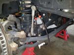
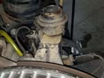
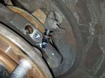
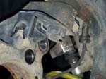
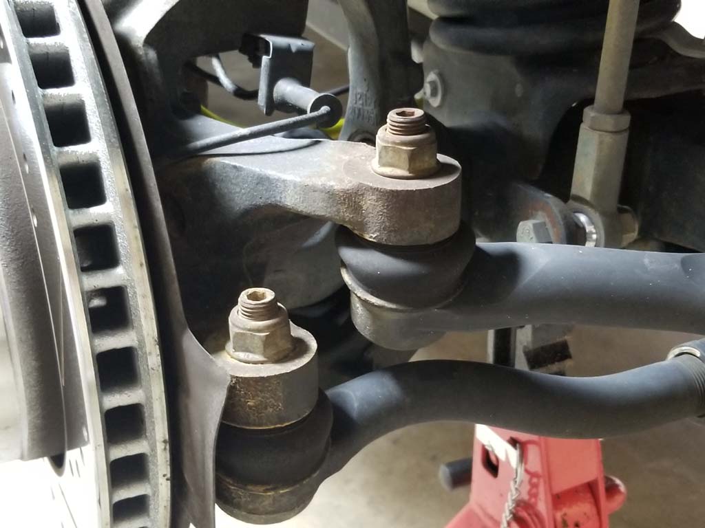
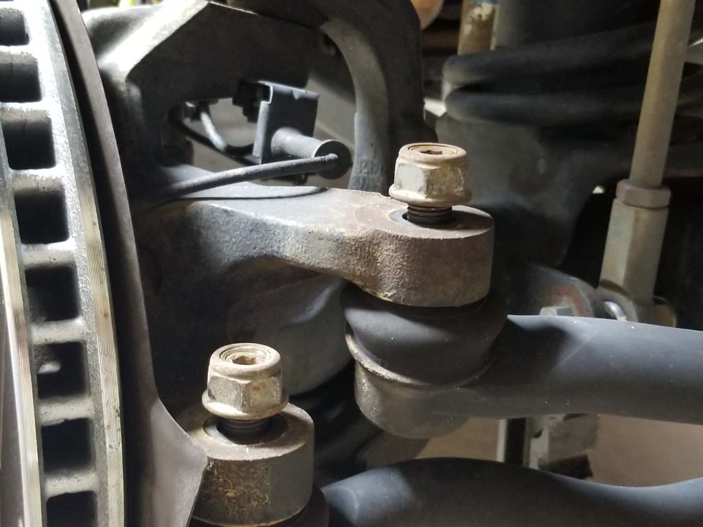
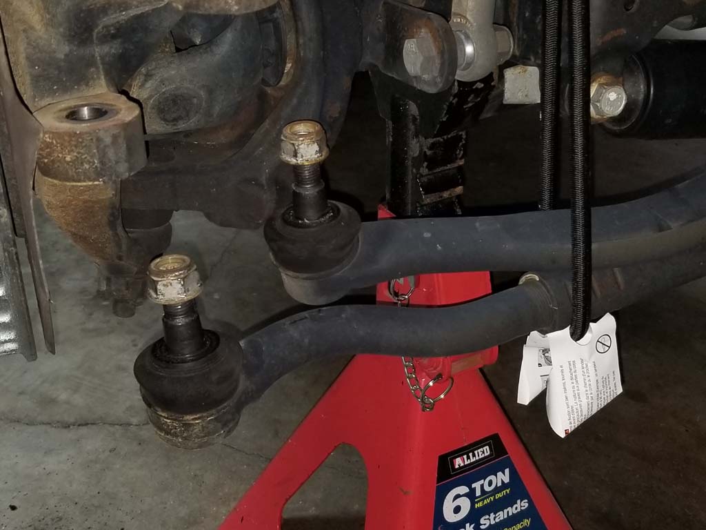
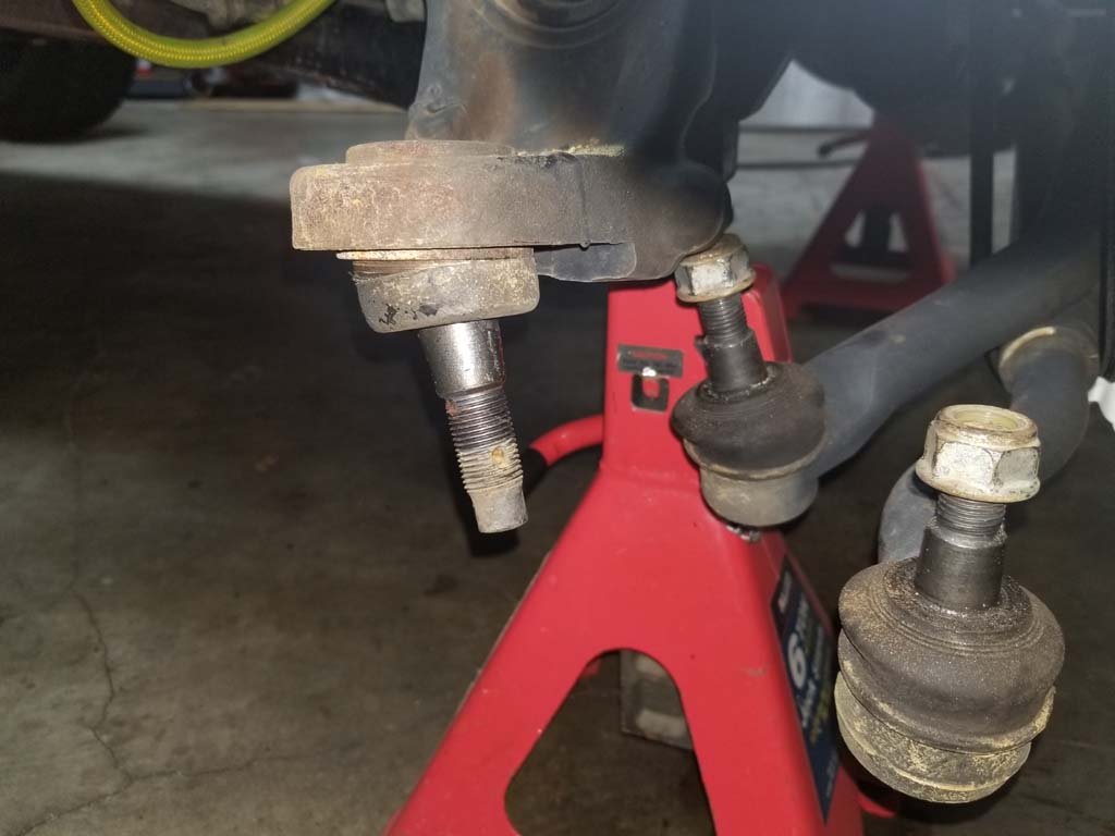
| 3. Starting on the passenger side. Loosen, but do not remove the nuts holding the drag link and tie rod end joints to the steering knuckle. You will need a 21mm socket and breaker bar. |
 |
 |
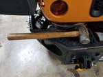
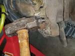
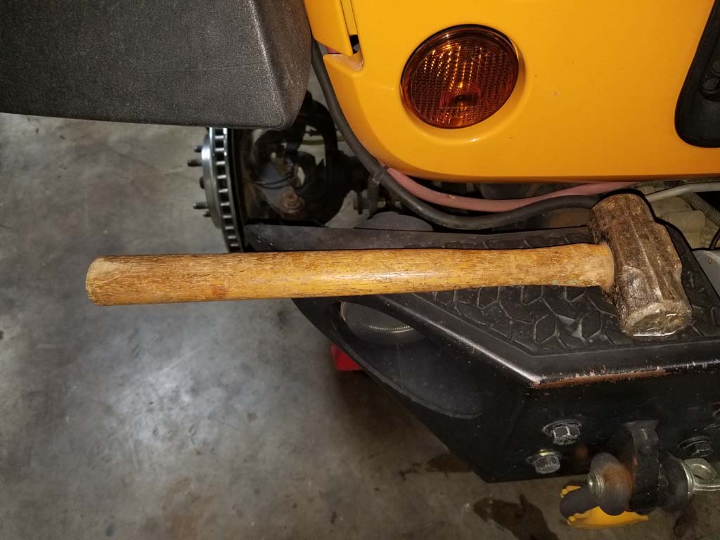
| 4. Using a large hammer strike the end of the steering knuckle where the drag ling and tie rod ends attach. The joints are a tapered design so a few good raps with the hammer should allow them to drop fee. |
 |
 |
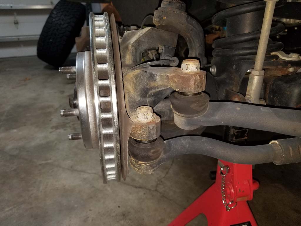
| 5. Once the joints are loose from the steering knuckle wrap a bungee cord, or rope around the tie rod and drag link so they don't drop and bind up the opposite end. Remove the nuts and remove the tie rod and drag link from the passenger steering knuckle. Reintall the nuts to protect the threads and so you don't lose them across the floor. |
 |
 |
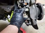
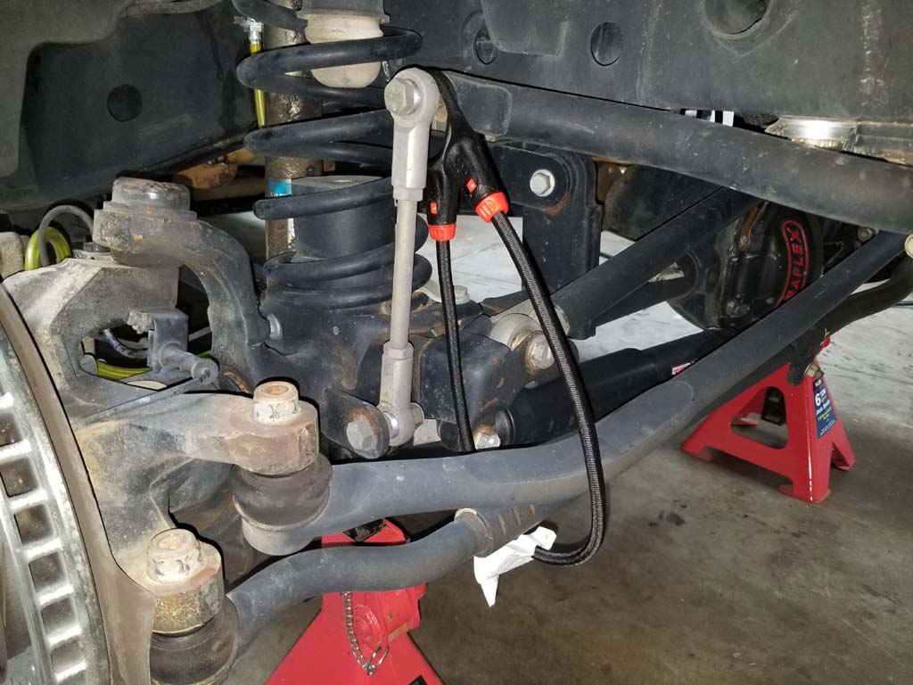
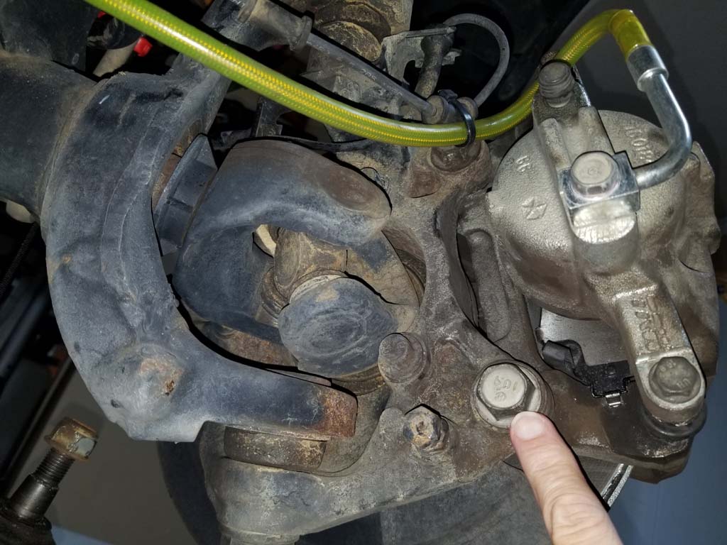
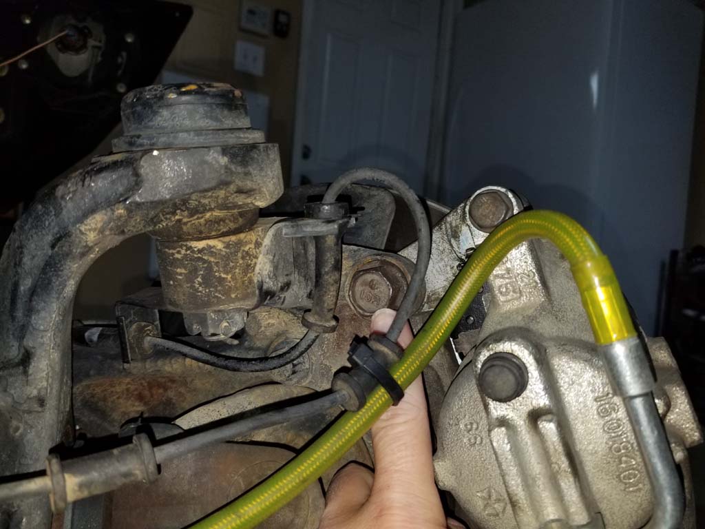
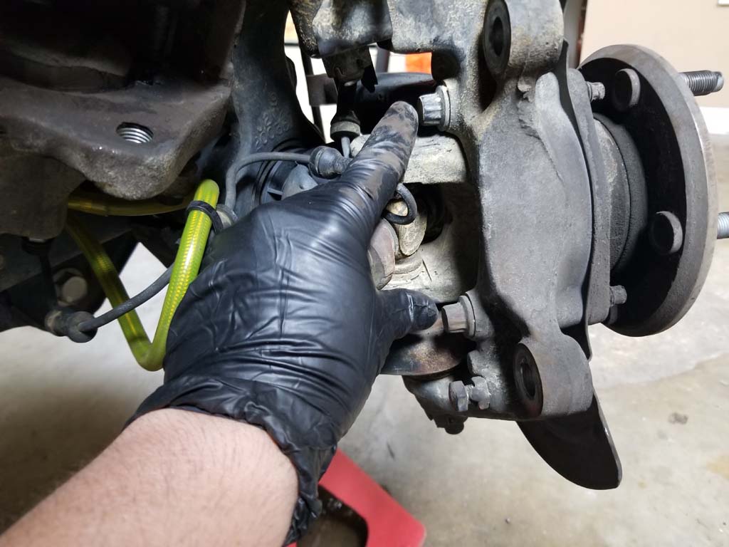
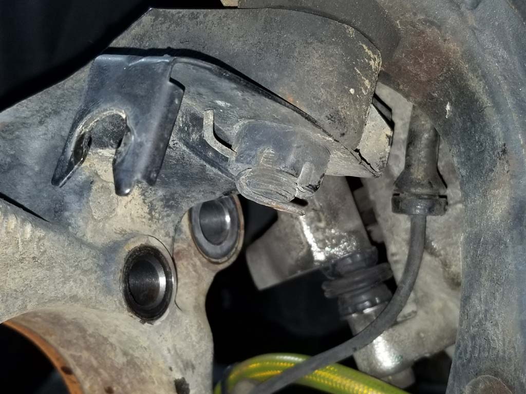
| 6. Remove the ABS sensor line from the bracket attached to the upper ball joint. These just slide out of the slots with a rotational motion back and forth. Cut any zip ties nearby so that you can move the caliper out of the way. |
 |
 |
 |
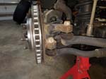
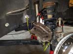
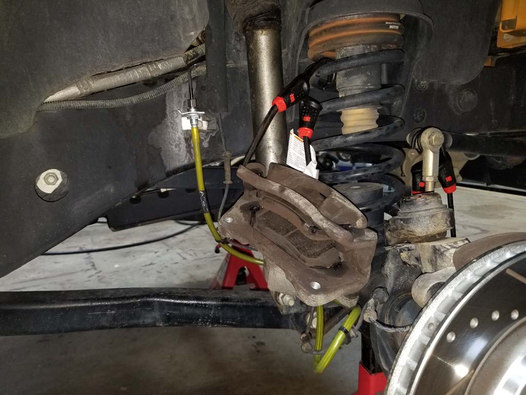
| 7. Remove the brake caliper and brake caliper bracket by removing the two bolts holding the brake caliper bracket to the steering knuckle. You will need a 21mm socket or 21mm combo wrench. |
 |
 |
| 8. Install a lug nut on one of the studs. Lift the caliper away from the brake rotor and support the caliper with a hanger. |
 |
 |
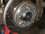
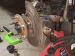
| 9. If you have the stock rotors you may have some retaining clips installed that will need to be removed with a small flat tip screw driver and needle nose pliers. Remove the lug nut, remove the rotor and carefully set aside. |
 |
 |
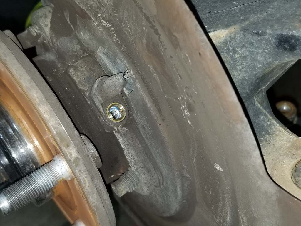
| 10. Remove the screw holding the wheel speed sensor into the unit bearing. You will need a 5mm allen wrench or socket. You can wiggle the sensor loose, but will not be able to remove it at them moment. |
 |
 |
11. On the backside of the unit bearing are three 12 point bolts. Loosen these bolts and back them out about 1/2" or until the tip is flush with the outside of the hub. You will need a 13mm 12 point combo wrench or socket.
Note: These can be in very tight. |
 |
 |
12. Using a hammer tap the back of each bolt to loosen the unit bearing from the steering knuckle. Mine can out fairly easy, but people have said that it can be difficult. Make sure you are working back and forth on the bolts, not just on one side. Once you get the hub free do not remove the bolts yet.
Note: You can place an old 12 point socket over the bolt head, use an impact hammer, or even a second hammer inbetween the bolt head and the hammer to lessen the chance of damaging the bolt head. |
 |
 |
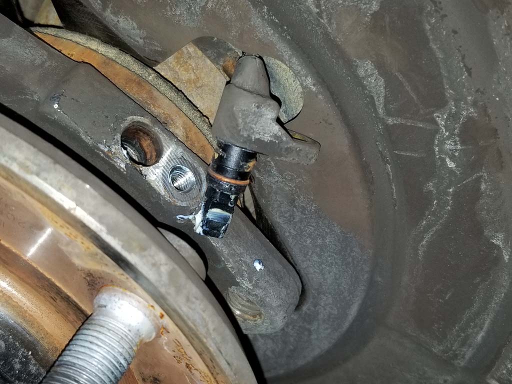
| 13. Now that the hub is free you will have enough room to move the dust shield so you can pull the wheel speed sensor up and out of its hole. Remove the wheel speed sensor by pulling straight up until the tip clears the hole. Do not pull using the cable. You can use a flat tip screw driver to gently pry up on the sensor to help get it clear of the hole. Make sure you don't bend or pry the sensor tip itself while removing it. Feed the sensor through the dust shield hole and move it out of the way. |
 |
 |
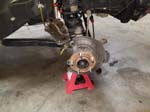
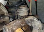
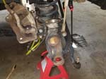
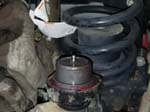
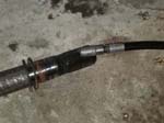
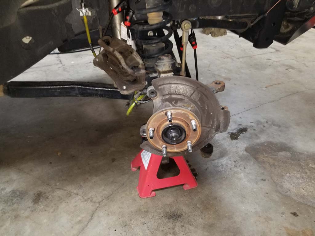
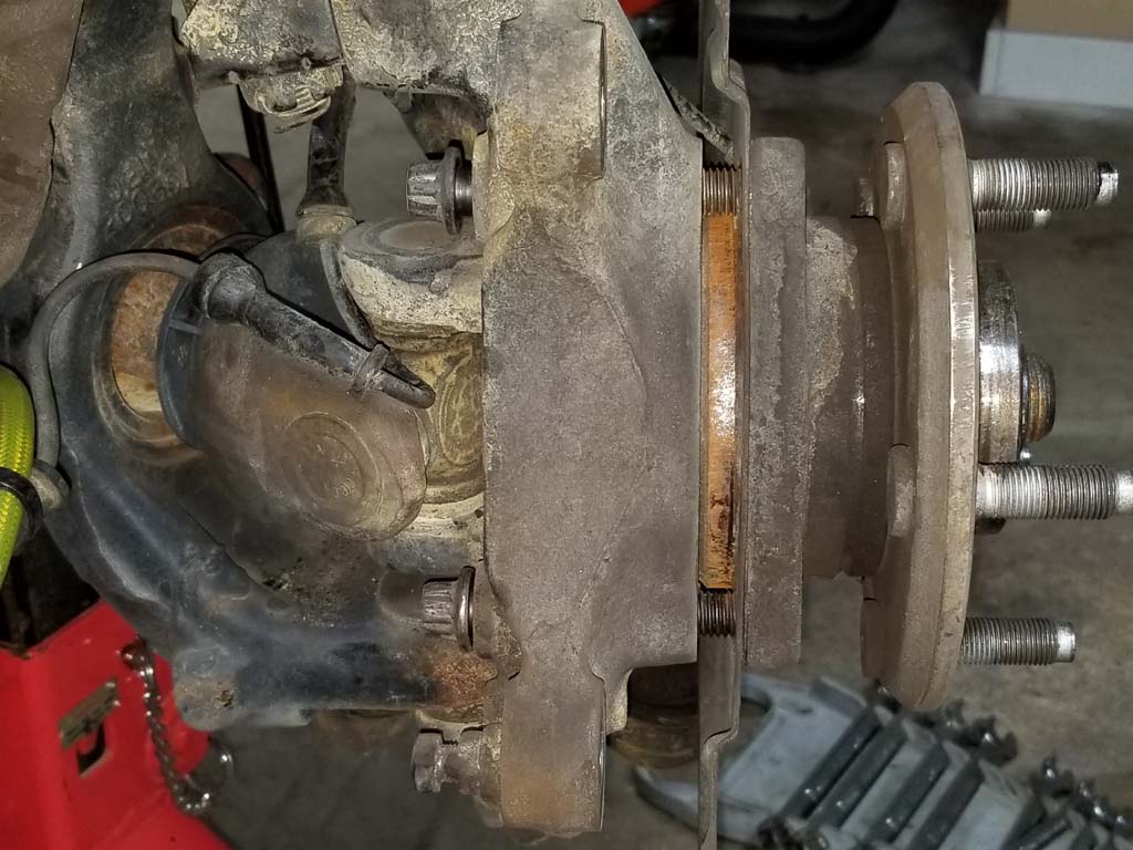
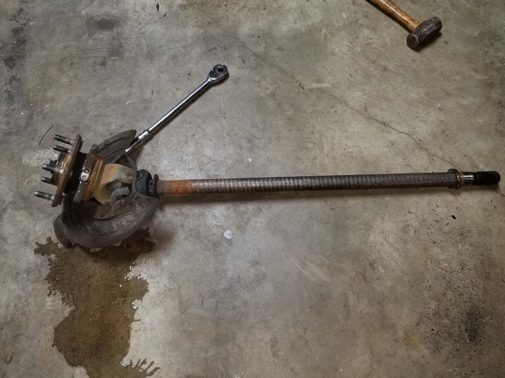
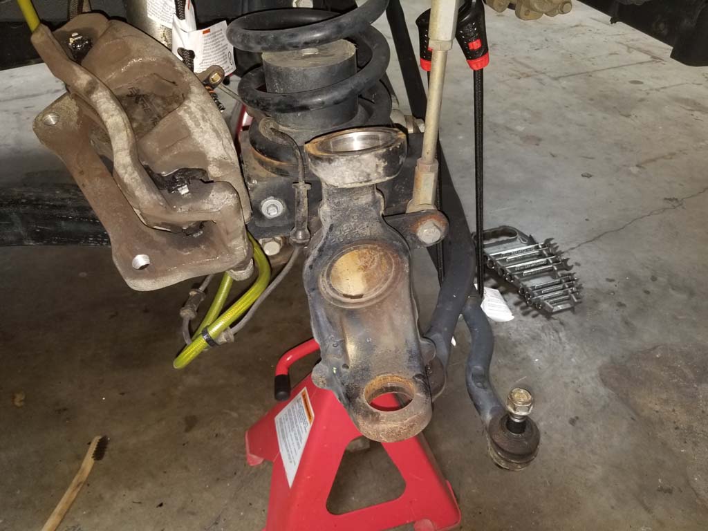
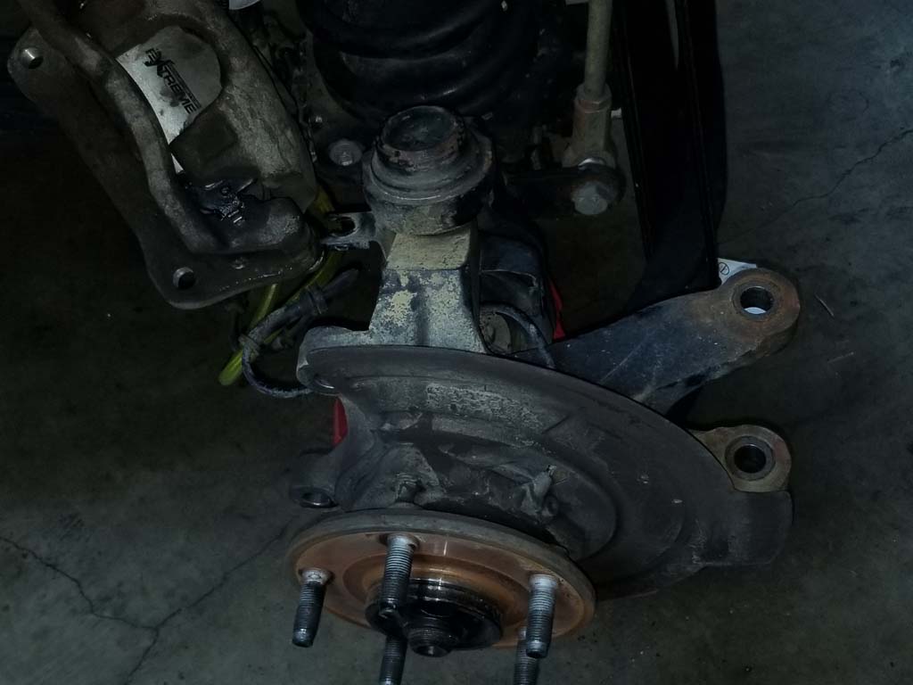
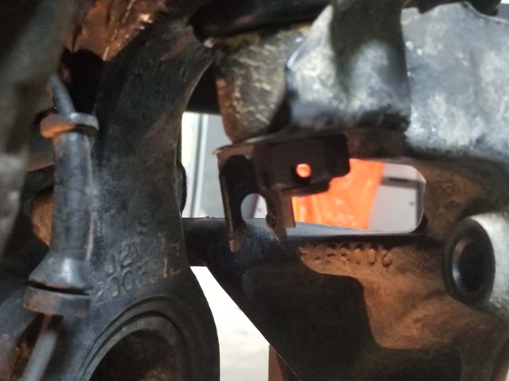
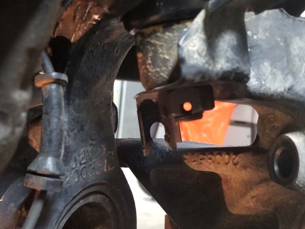
14. Completely remove the bolts holding the unit bearing to the steering knuckle. Pull the unit bearing and axle shaft out of the axle tube and steering knuckle. You need to keep it straight until it clears the shaft seal that is located by the differential. This is probably about 6" worth of pulling before it clears. If you have OEM shafts there is a rings on the shaft that will help you keep it centered in the axle tube. If you don't have any on the shaft when it comes out, take a look inside the shaft to make sure they didn't fall off and are laying in the axle tube.
Note: That's water on the floor from the wife's wet car, not the axle shaft. |
 |
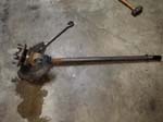 |
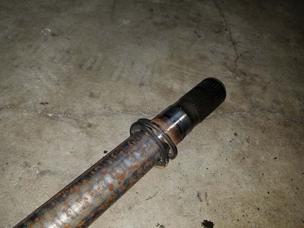
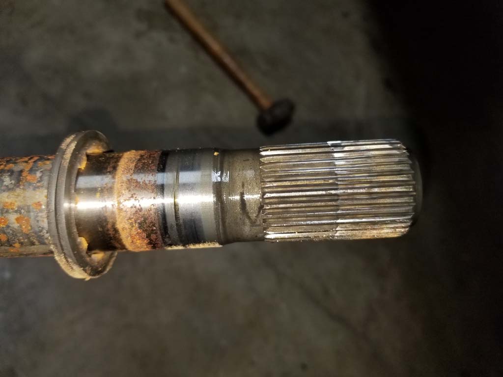
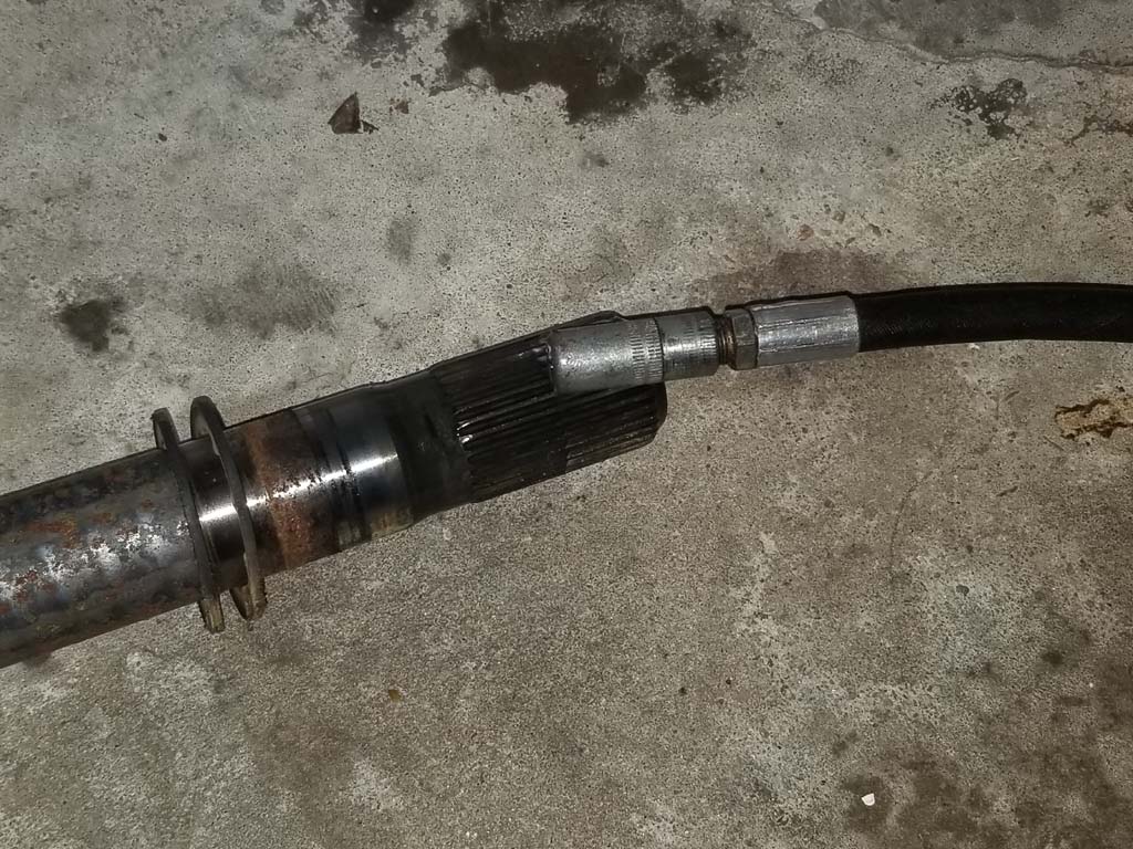
| 15. Once you get the shaft clear it is a good time to inspect the shaft and end splines for any damage. You can see the rings in the pictures. You can also see where the splines are engaged in the differential and where the seal rubs against the shaft. I checked to make sure that I didn't have any twisting, damage splines or burrs on the shaft. There was a little surface rust down along the shaft, but not enough that I felt any need to address and clean up considering the shaft was 8 years old. |
 |
 |
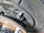
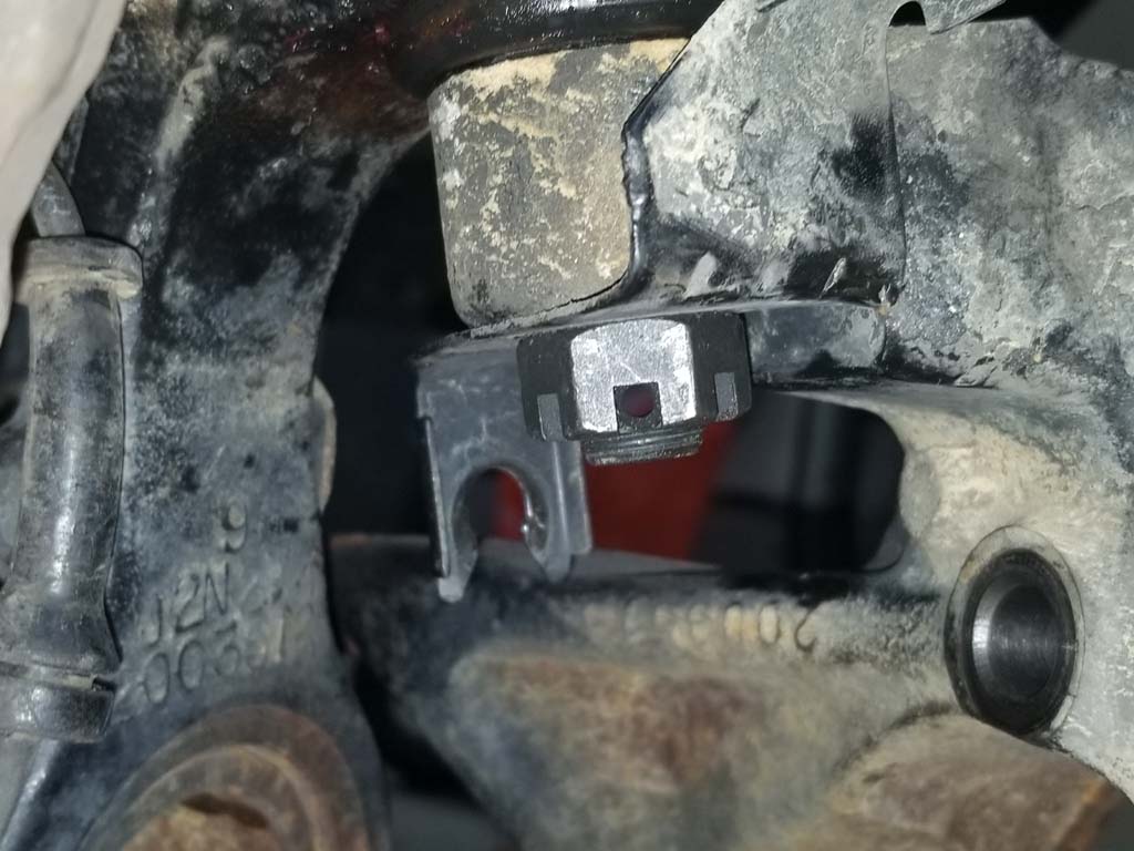
| 16. Remove the cotter pins from the upper and lower ball joint nuts. You will need a needle nose pliers to bend the ends and pull them out. |
 |
 |
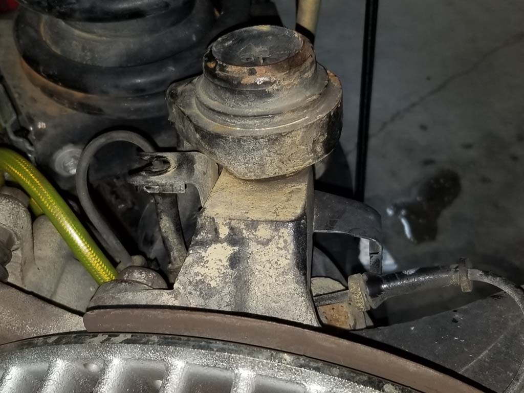
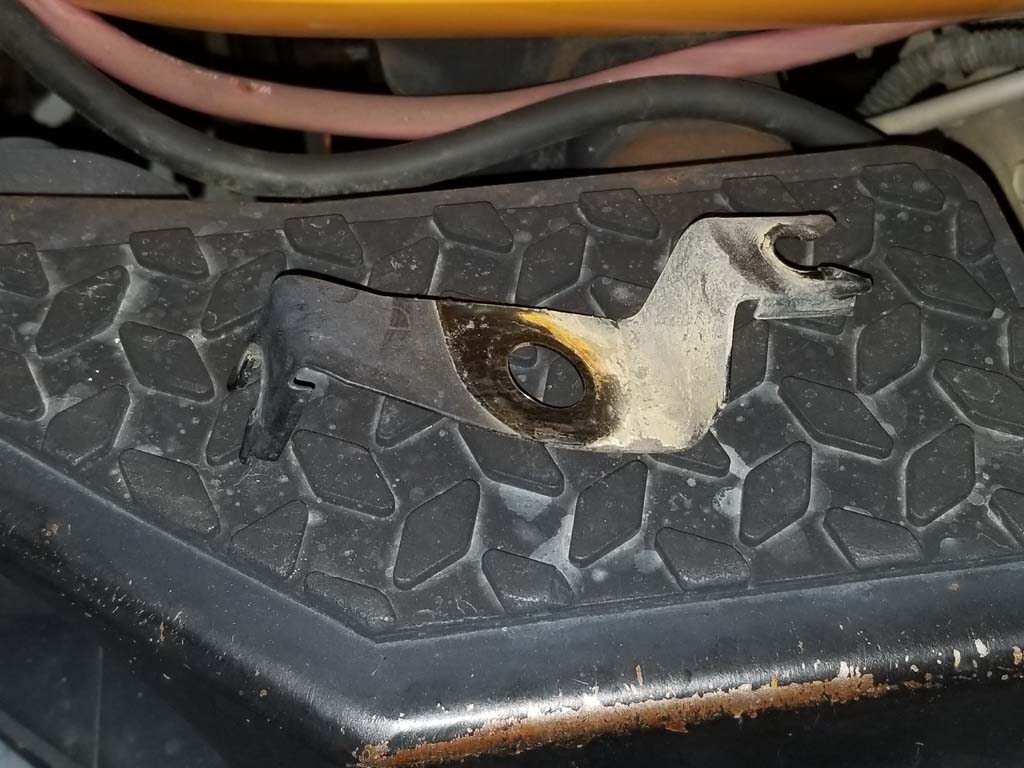
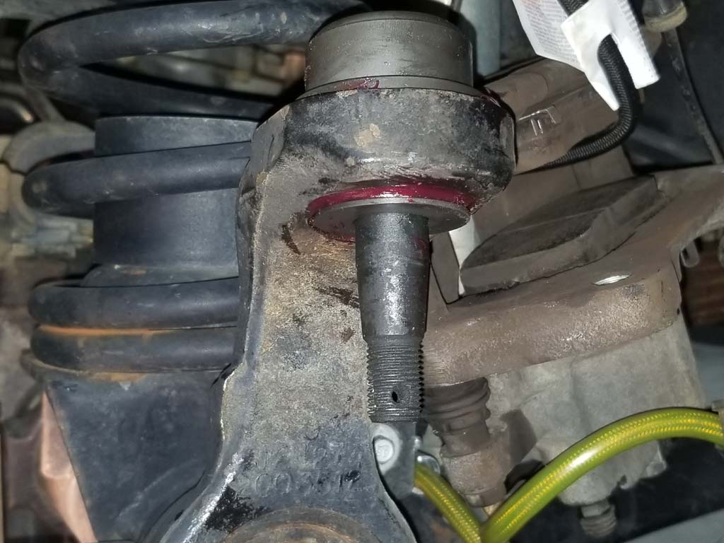
| 17. Remove the upper ball joint nut and wheel speed sensor bracket. Make a note of how this bracket goes on. The horizontal holder goes up and to the rear of the Jeep. In the picture the rear of the bracket is on the right. These are side specific. Thread the nut back onto the ball joint stud. Loosen the lower ball joint nut, but do not remove from the stud. Both nuts should sit flush with the end of the ball joint studs. This is to prevent the steering knuckle to fall off when you free it from the tapered studs in the next step. You will need a 22mm socket or combo wrench for the upper ball joint nut and a 24mm socket of combo wrench for the lower ball joint nut. |
 |
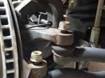
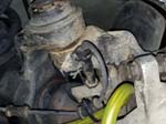
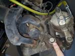
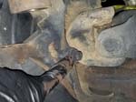
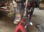
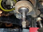
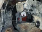
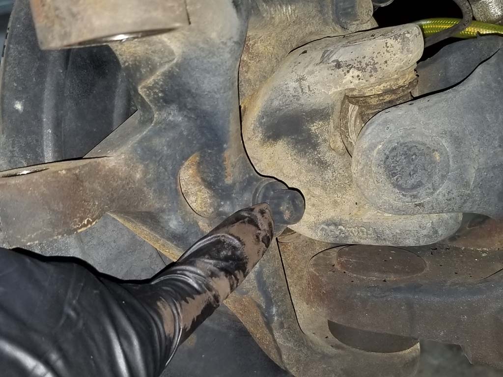
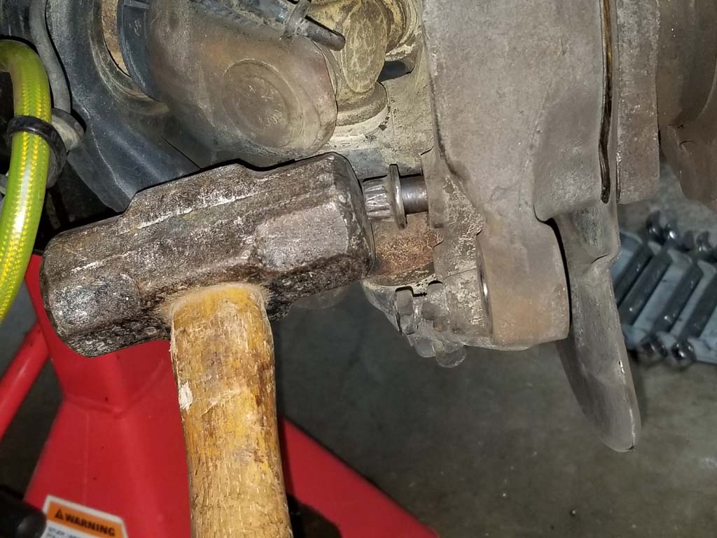
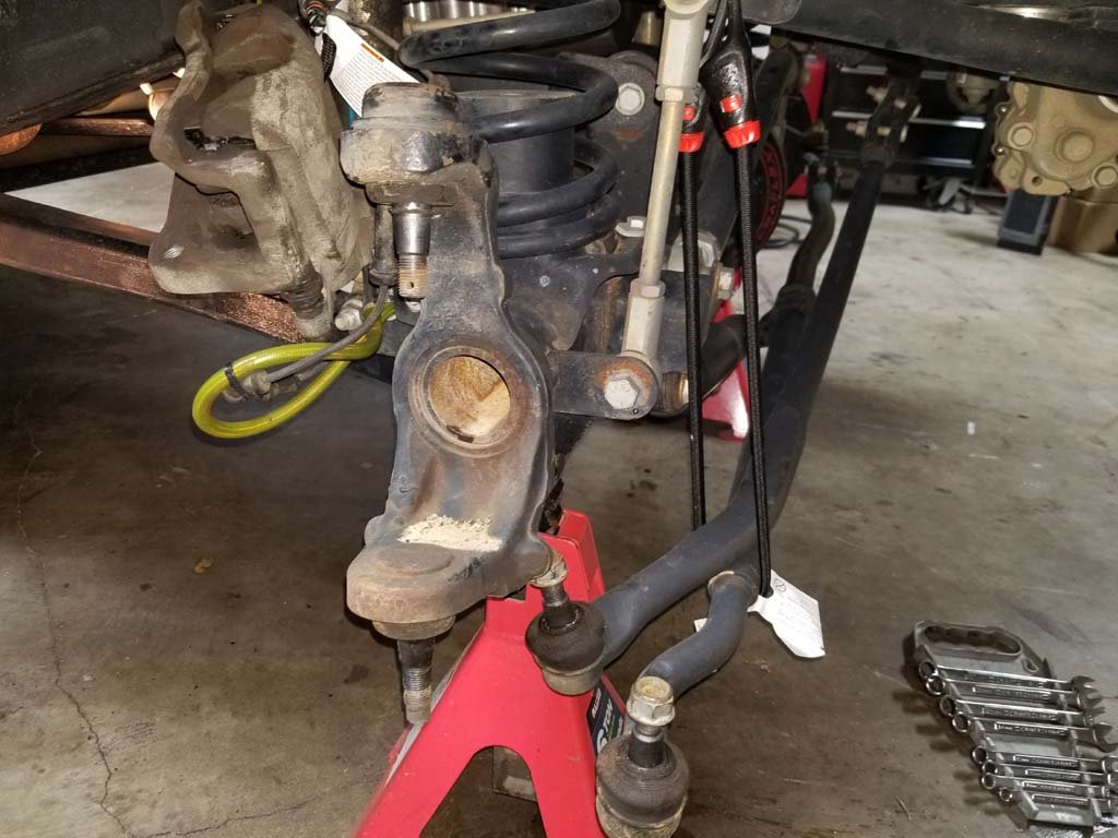
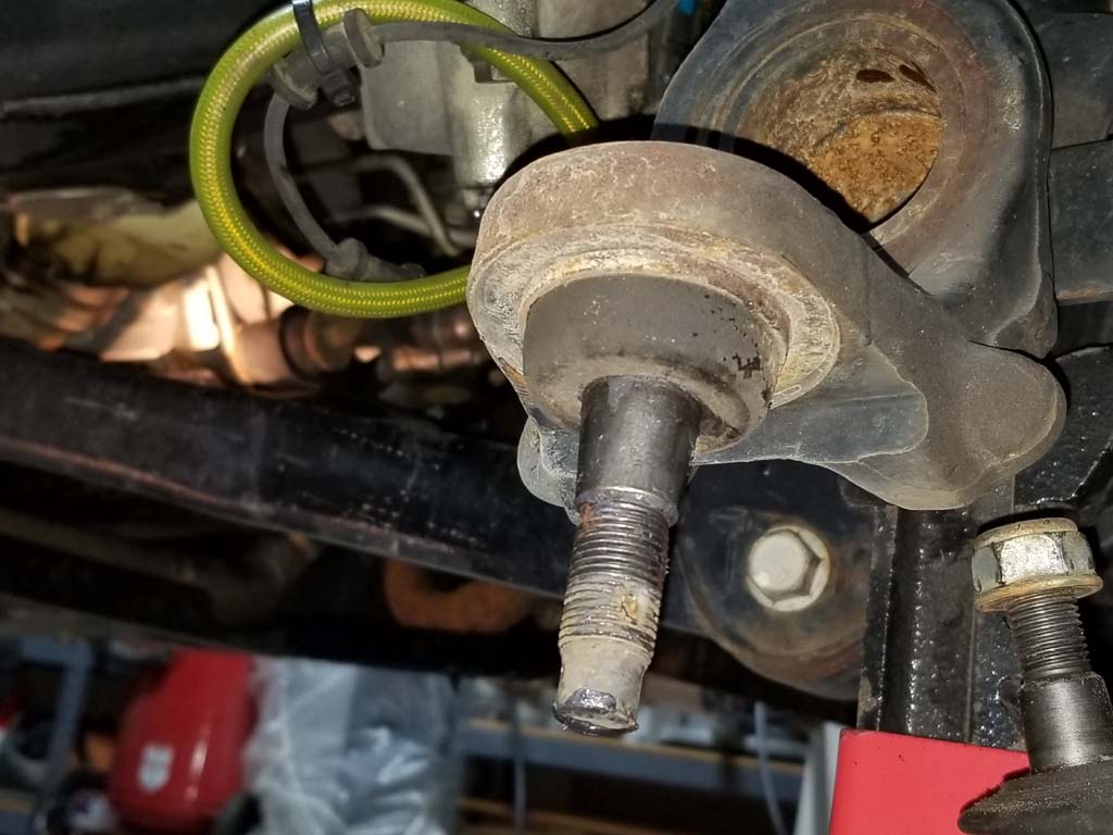
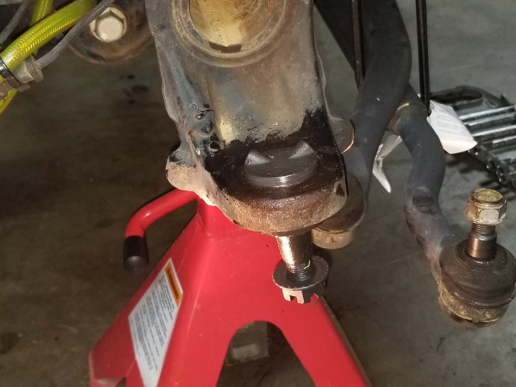
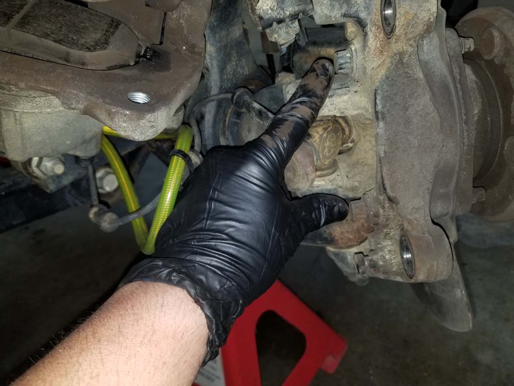
| 18. Hit the steering knuckle right at the location of the ball joint studs. The ball joints have a tapered stud just like the drag link and tie rod ends. A few good raps with the hammer should allow the steering knuckle to drop free from the ball joint studs. |
 |
 |
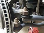
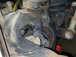
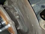
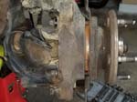
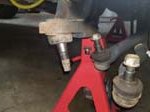
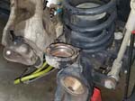
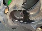
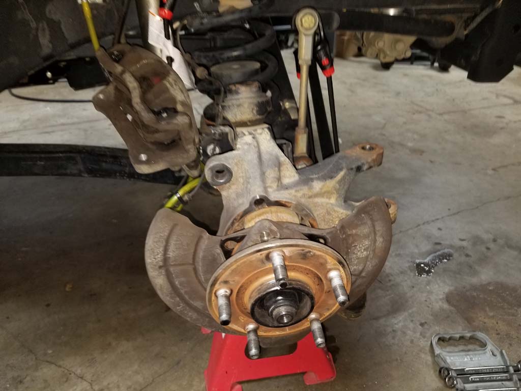
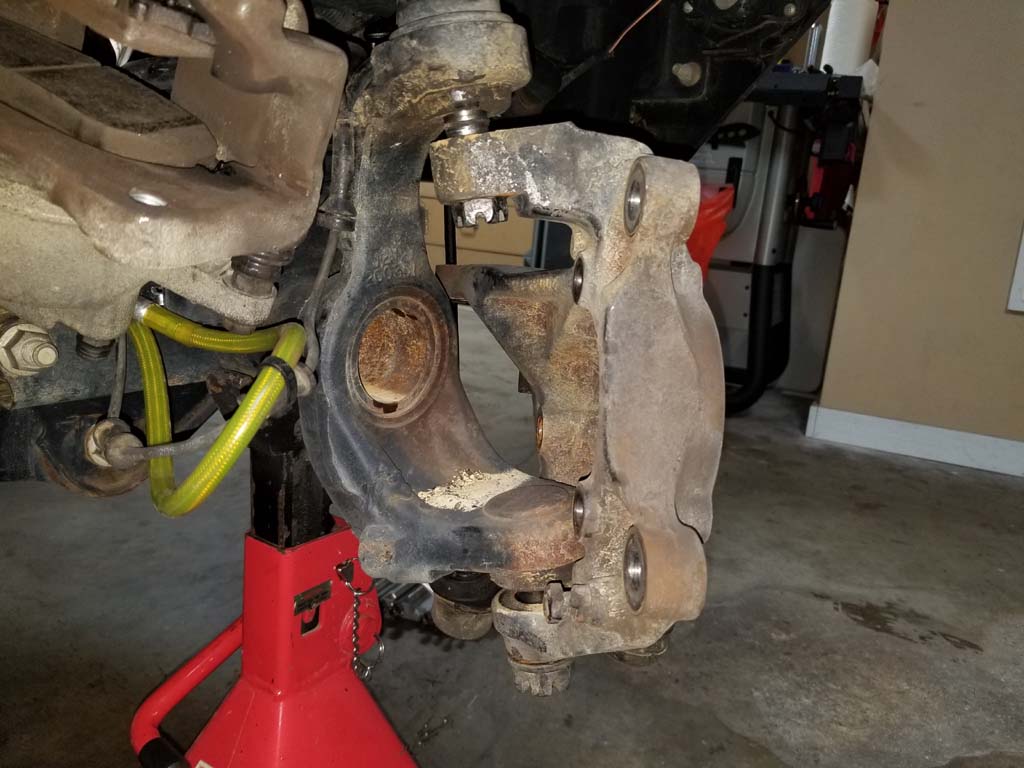
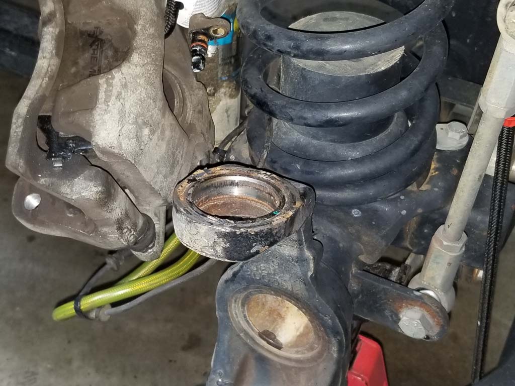
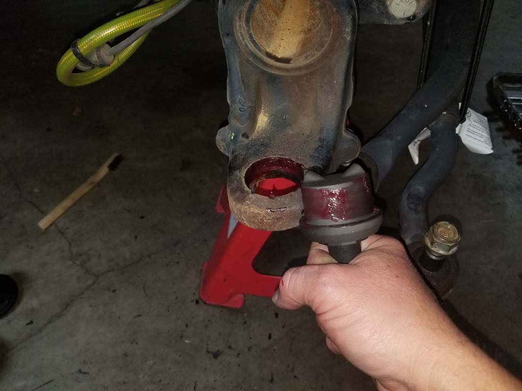
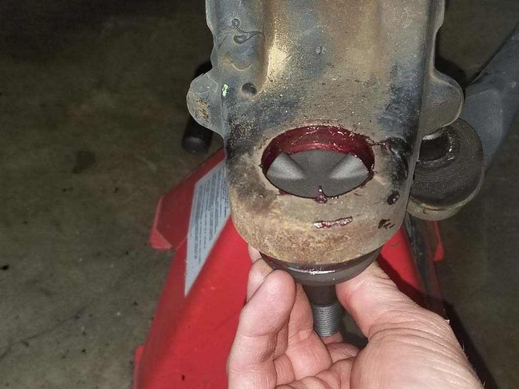
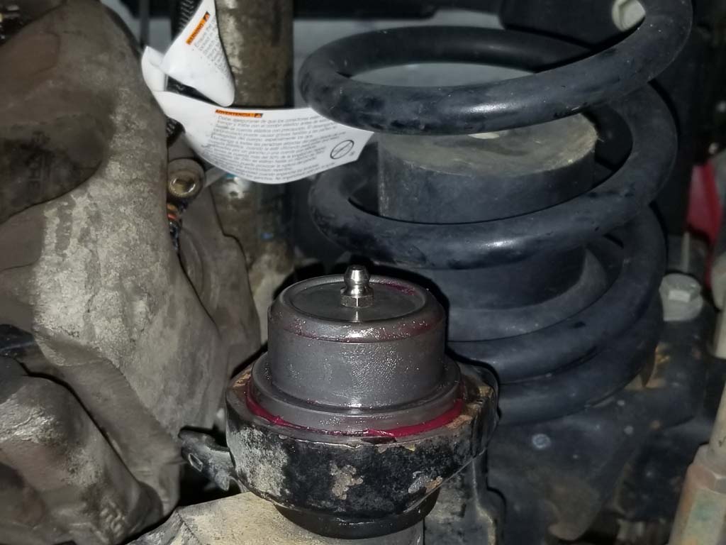
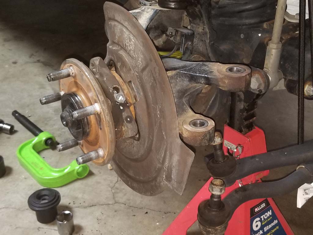
| 19. Remove the nuts from the ball joint studs and remove the steering knuckle. Inspect the ends of the steering knuckle where the taper stud of the ball joint sits. These should be nice and clean with no burrs or damage. |
 |
| This is where I was shocked I hadn't seen any indications of bad ball joints. The bottom ball joint that handles the load up and down was completely shot. It took no pressure to move it back and forth, spin it and move it up and down almost 1/2". I did pull the boot off the lower ball joint and there was still grease inside, so just a wear issue. The upper ball joint didn't move up and down, but took zero force to move it around also. |
 |
 |
 |
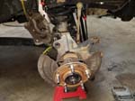
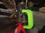
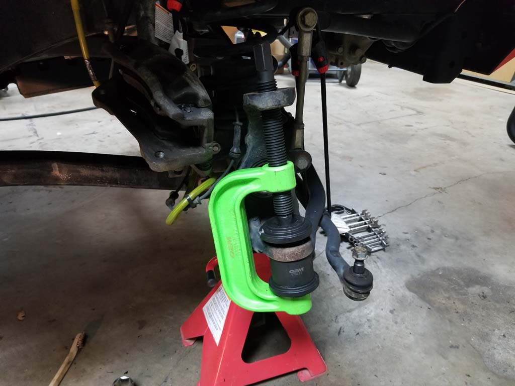
20. Press out the ball joints using a ball joint press. Starting with the lower ball joint and then the upper. The lower ball joint presses down and out while the upper joint presses up and out.
Note: I had camera issues at this point, so many pictures are missing of using the ball joint press. I recommend searching on youtube for some good videos on this tool, it can be a little confusing in it's operation for something very simple. At about the 3:12 point Teraflex Ball Joint press YouTube video. Even there press may be different than what you have, but at least you have an idea of how it works. |
 |
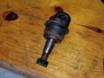 |
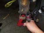
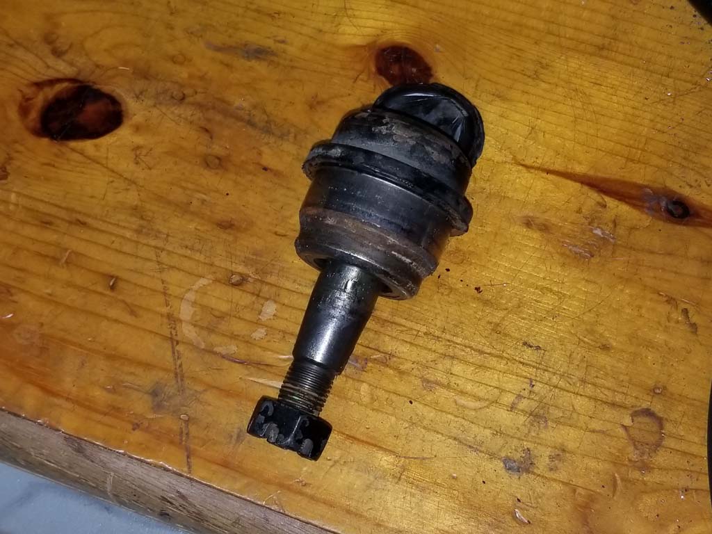
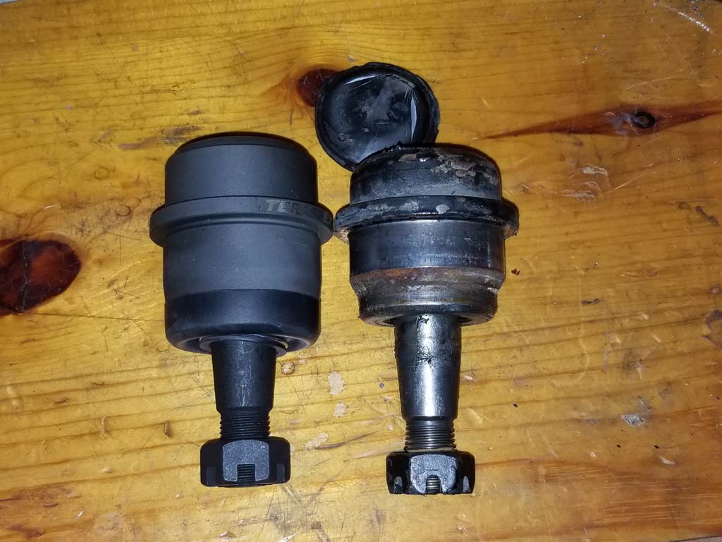
| Comparison of the old and new upper ball joints |
 |
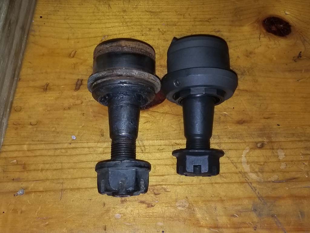
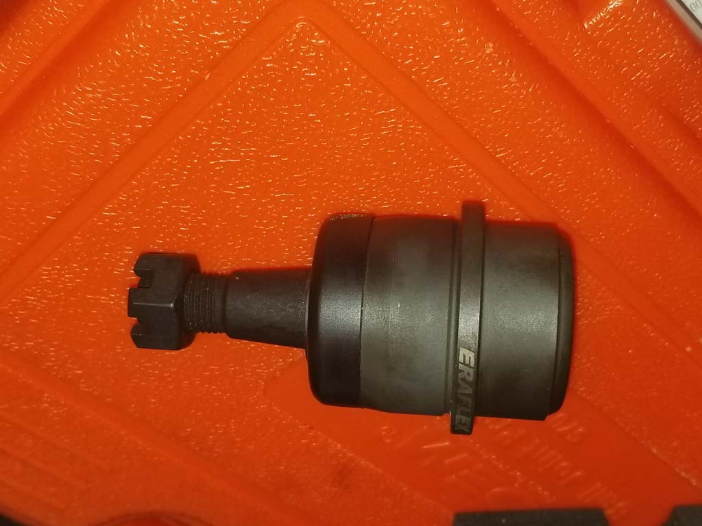
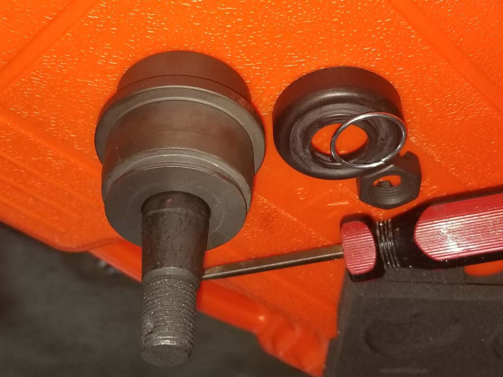
Comparison of the old and new lower ball joints. You can clearly see the adjustment ring on the new lower joint. |
 |
| |
| Installation: |
| 21. Clean the upper and lower ball joint surfaces. I used a shop vac to clean out what I could of any dirt that had gotten into the axle shaft also. |
 |
 |
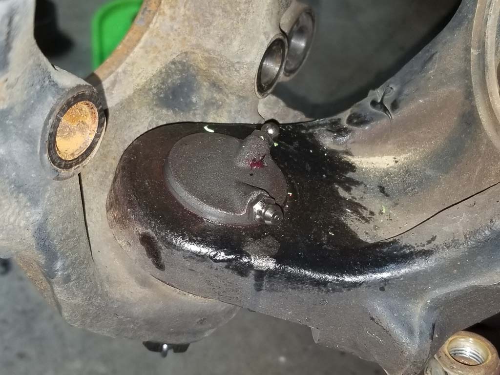
| 22. Grease the outside of the lower Teraflex HD ball joint and the inside of the steering knuckle. Press the ball joint up into the steering knuckle. Make sure you align the grease fitting holes depending upon if you have a stock shaft or RCV shafts. I have stock shafts so the grease fitting will point towards the inside of the steering knuckle. If you have RCV shafts the grease fitting will face towards the outside. The ball joint should stay in the steering knuckle long enough for you to get the ball joint press positioned. |
 |
 |
| 23. Press the Teraflex HD ball joint in with the ball joint press until the bottom lip of the ball joint is flush with the bottom of the steering knuckle. |
 |
 |
24. Remove the rubber dust boot from the upper Teraflex HD ball joint. You may need a small flat tip screwdriver to work the boot free.
Note: If you press the upper ball joint into place with the rubber boot on, you run the risk of tearing the boot and needing to replace it. |
 |
 |
| 25. Press the upper Teraflex HD ball joint into place with the ball joint press until the bottom lip of the ball joint is flush with the top of the steering knuckle. Reinstall the rubber dust boot onto the ball joint. I recommend starting with the back side where the boot goes between the ball joint and the machined edge of the steering knuckle. I used a small flat tip screwdriver to push it up and onto the lip of the ball joint. |
 |
| 26. Install the grease fitting in the upper and lower ball joints. You will need a XXmm socket or combo wrench. |
 |
 |
| 27. Install the steering knuckle and upper ABS line bracket. Tighten the the upper and lower ball joint nuts to 70 ft/lbs. The upper ABS line may rotate, if it does you can use a screwdriver to hold it in place while you tighten the nut. |
 |
| 28. Apply grease to the splines and the seal surface of the shaft before you slide the shaft and unit bearing back into the axle. |
 |
| 29. Slide the shaft and unit bearing back into the axle. Make sure you keep it level when you slide it back into the seal inside the axle tube. Do not push the unit bearing all the way into the steering knuckle. |
 |
| 30. Position the dust shield and feed the ABS sensor through the opening and install the sensor in the hole in the unit bearing. |
|
|
|
| 31. Push the unit bearing all the way into the steering knuckle and install the 3 unit bearing bolts . |
|
|
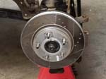
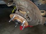
| 32. Reinstall the brake rotor. Don't forget to place a lug nut on the stud to hold the rotor on. |
|
| 33. Reinstall the brake caliper on the rotor. Use some red locktite to make sure these bolts don't come loose. |
|
|
|
| 34. Reinstall the ABS line in the bracket |
|
| 35. Reinstall the tie rod and drag link ends in the steering knuckle. |
|
| 36. Make sure all the lines are clear of the rotating parts. Grease the upper and lower ball joints with bearing grease. |
| 37. Reinstall the tire. |
| 39. Repeat the above on the driver side, only difference is you only have the tie rod nut to deal with on the driver side. |
| 40. Once you have completed both sides, remove the differential fill plug and refill the differential with oil. |
| |


