Special Thanks to Jim Conforti for finding the part numbers
for us and doing the original installation. This has been adapted
off of his instructions and the 2003 FSM. This will work on a Rubicon,
or any 2003 TJ that could come with it as an option. (To tell, look
down in front of your radiator from the outside and look for a harness
with a plug sort of lonely by itself on the driver side)
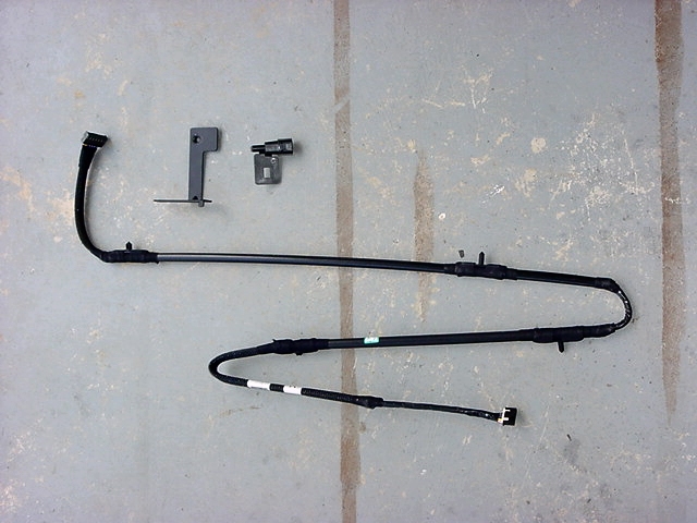
Wiring
Harness: If
you have a soft top you will need to put it down.
1. Move sun visors out of the way.
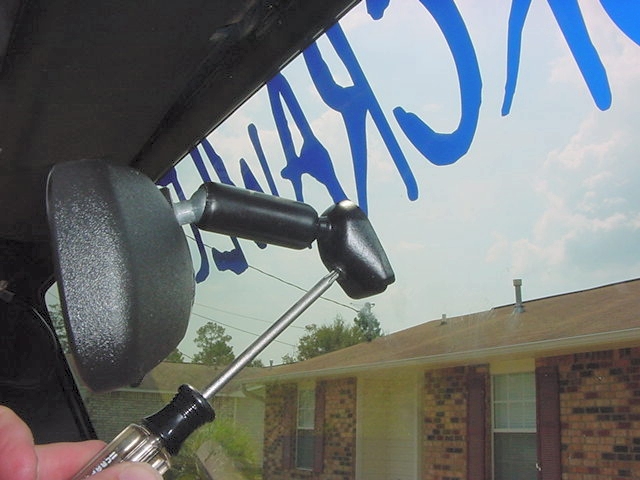
2. Unscrew the T-20 Torx screw from the bottom of the mirror base and
remove the old mirror.
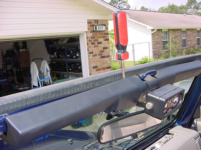
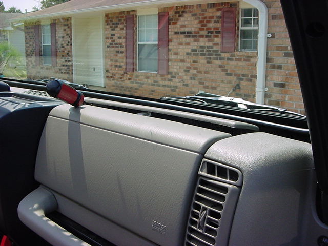
3. Pull off center trim section on top of windshield by carefully inserting
a screwdriver in behind it. There are (4) clips that hold it
in place. If one of the clips come off, just remove it with
a pair of pliers.
4. Pull up the center dash cowl cover, buy gently prying up on one
side and working your way across.
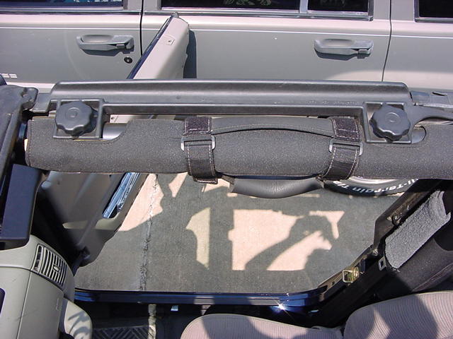
5. Remove the (2) hand bolts that hold the passenger side door surround
to the roll bar and remove the passenger side door surround.
6. Remove the Passenger side visor.
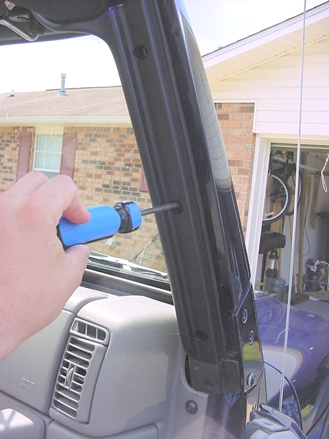
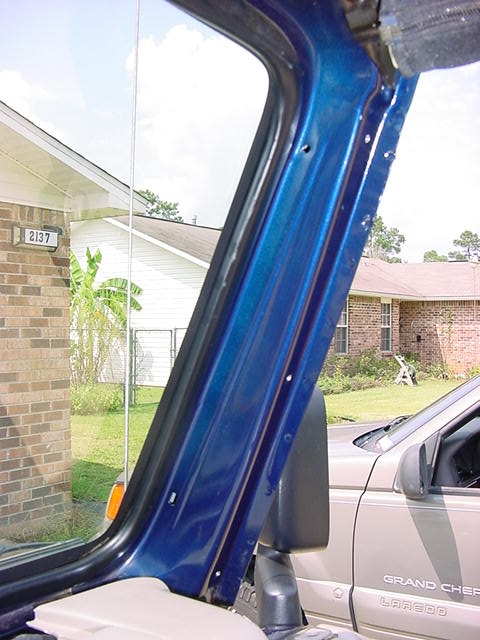
7. Remove (3) Phillips screws from the passenger side A-pillar trim
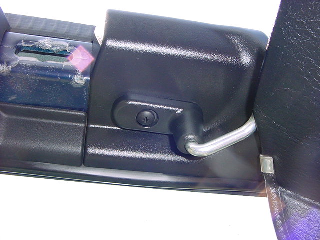
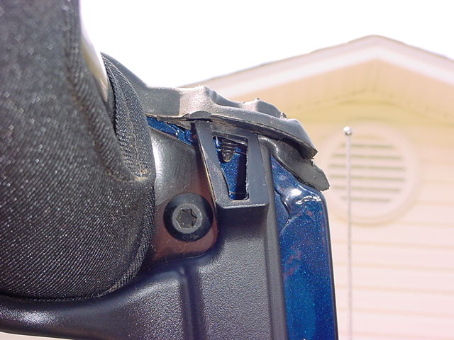
8. You will need to push the top seal retaining clip out of the surround
with a screwdriver. Take it slow so that you don't damage anything.
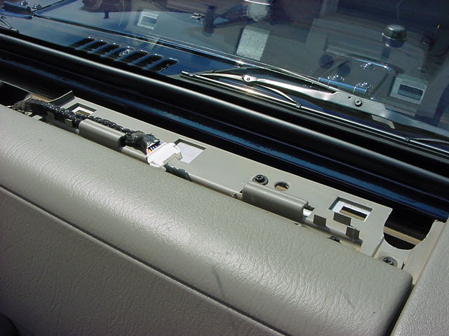
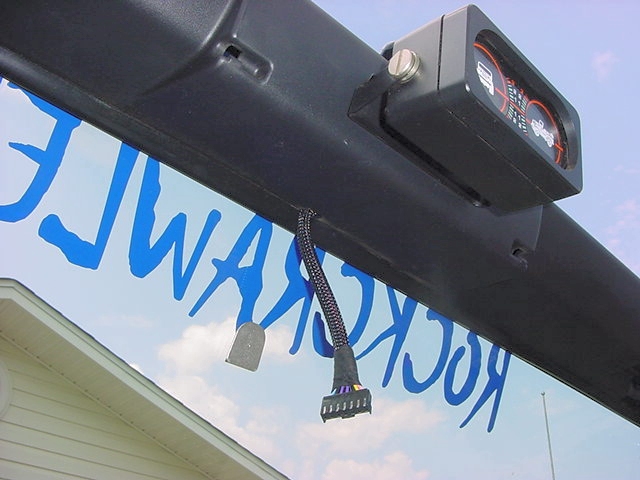
9. Take a look at the plugs on the wiring harness so that you have the
right side for dash connector. Don't connect this yet.
Now route the harness through the clips on the dash. Then insert
the push clips into the holes provided in the A-pillar and windshield
frame. This should leave you with the mirror connector just
hanging in the center of the windshield.
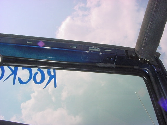
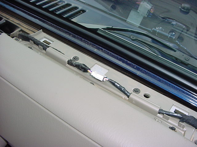
10. You can now place all the trim and door surround back except for
the cowl cover piece. The center trim section for the windshield
has a locator pin on it, so make certain it goes in the hole and
that your mirror connector goes through the little slot in the bottom.
11. Install the new mirror and clip the connector into it. Reinstall the
T-20 Torx screw. Be careful tightening the screw down, you can
crack the windshield if you tighten it to much. It should be
just tight enough to stop the mirror from moving around.
12. Now plug in the dash connector.
13. Replace the cowl cover.
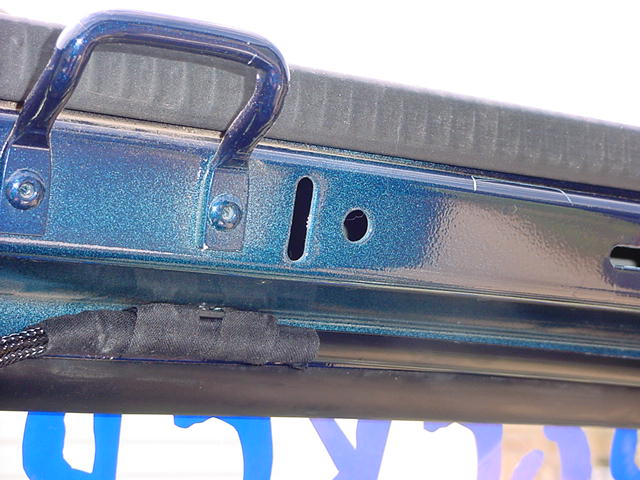
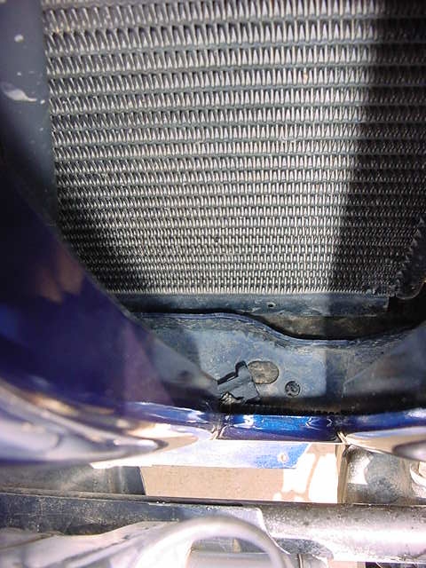
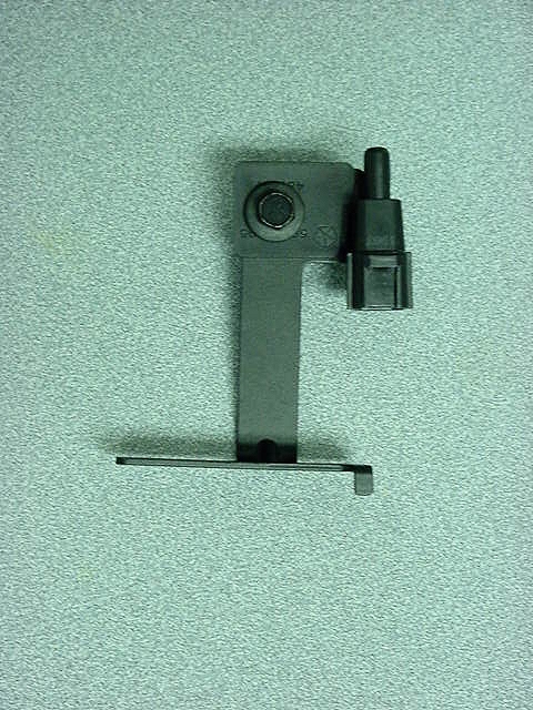
Temperature
Sensor 1. Look thru the grille (second slot in on driver side) and
down into the bottom for the wire and connector.
2. You will need to unhook this plug. It is held in by a plastic
connector, I think they call them trees, from the bottom. I
got mine out by pushing it up and through from underneath.
I pulled back the rubber splash strip from underneath the radiator
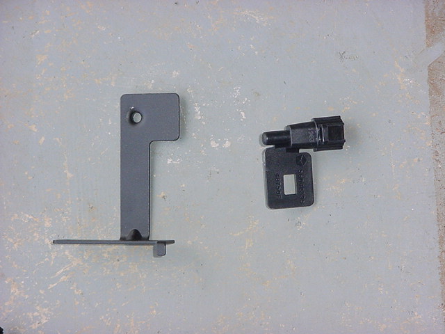
3. Install the sensor to the bracket with one of the body bolts (10mm
socket)
4. Now connect the wiring harness to the sensor and thread the bracket
back into the grill.
5. Bolt the bracket back inside the grill with the second body bolt.
Getting
the whole thing to work. Variance: (You must set this
before you can calibrate the compass.)
Turn the ignition On, and press and hold the center button of 3 to
6 seconds. The last variance zone number will be displayed (Z#).
Each press of the center button will select a new variance zone.
When the proper zone is selected, wait 5 seconds to resume normal
operation. See Owners Manual page 44 for variance map.
This is the Variance map from the FSM.
Calibration:
Turn the ignition On, and press and hold the center button for 6
seconds to change the display between VAR (compass variance) and
CAL (compass calibration) modes. To recalibrate the compass,
CAL should be displayed for a complete one and a half 360 degree
turns in an area free from large metal objects or power lines.
When the compass has been calibrated, CAL symbol will turn off and
the compass will function normally.