I had been looking for a way to fix the issues of a lifted
Jeep and the steering. Even though I didn't have any bump steer, I
still had problems with the front drag link hitting the during a hard
right turn. The steering still felt a little vague at times on the
road. I had been looking for a way to solve the hitting issue.
Toys by Troy came out with a steering system that removed the K-link
steering that is on the TJ. I just wasn't fond of having to cut and
weld stuff on the front axle. So I kept looking. Then Off Road
Only released their U-Turn Steering. A
crossover steering design that eliminates steering toe change from
suspension height change. Parts of this write up come from Off Road
Only's Install directions.
| Installation: |
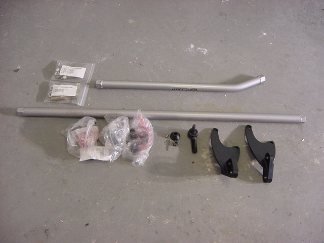
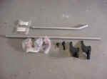
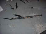
| These
area all the parts you receive for the U-Turn. |
 |
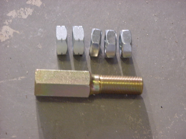
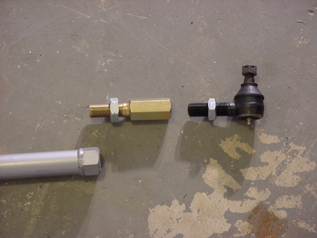
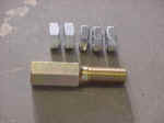
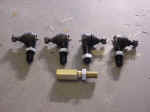
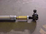
| 1. Assemble the Tie Rod Ends first. Locate the 4 tie rod ends and
the bag with the yellow zinc adjuster sleeve and jam nuts. There should
be 3 right hand Jam nuts and 2 left hand. The Left hand nuts are marked
with a tick on each of the 6 flat intersections. They are the
two on the left side of the picture. |
|
 |
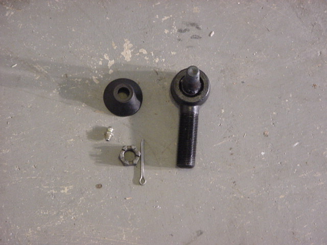
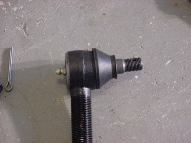
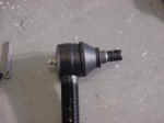
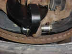
| 2. Install the boot over the tie rod end and the Zerk into
the bottom of the tie rod. You will need a 5/16" Combo
Wrench. The Zerk's are pipe threaded, so be careful to get them
lined up straight into the hole. You may need to press down
on them with your thumb to get them to go in straight. |
 |
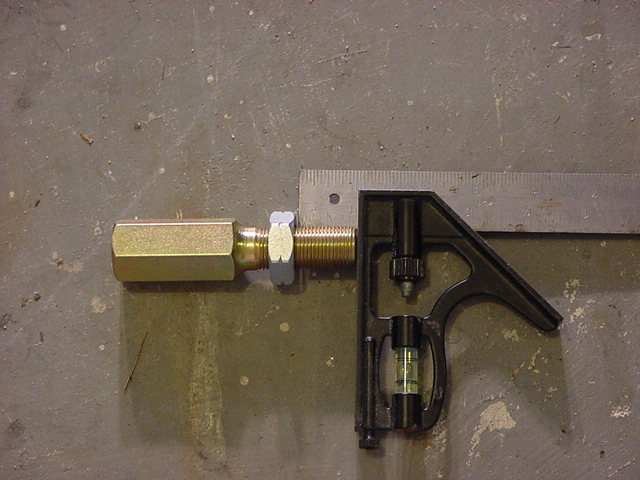
| 3. Now screw a left hand thread jam nut on to the adjustor sleeve, and
a right hand jam nut on to a right hand tie rod end. Crew in
the jam nuts until 1" of the threads are exposed. |
|
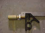 |
| 4. After kicking the jam nuts across the floor I decided to go ahead
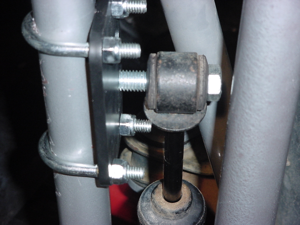
and screw the remaining jam nuts on to the tie rod ends. Note:
One of the ends is a left hand threaded end. |
 |
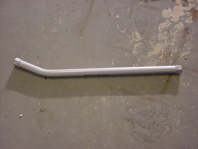
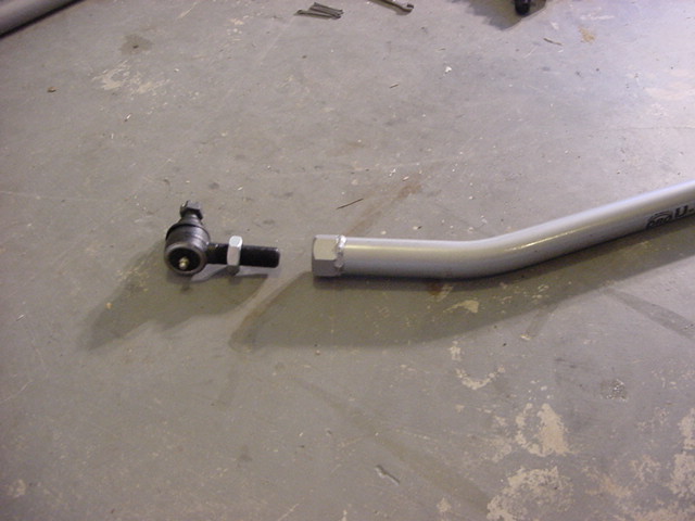
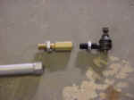
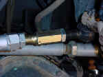
| 5. Locate the short bent drag link. You will be screwing the adjustor
sleeve and the right hand tie rod end from step 3 into this bar.
They screw into the long side of the bar. The end on the right
of the picture. Check the threads on the bar to make certain there
is no debris on the threads. |
|
 |
| 6. Screw the adjustor sleeve into the drag link until the jam nut seats
against the drag link. Be careful not to turn the jam nut. |
 |
| 7. Now screw the tie rod end into the adjustor sleeve until the jam nut
seats against the adjustor sleeve. Be careful not to turn the
adjustor sleeve or the jam nut on the tie rod end. |
 |
| 8.
Adjust the Jam Nut on one of the right hand tie rods to leave 3/8"
of thread showing behind the jam nut. |
 |
| 9. Screw the tie rod end into the opposite end of the drag link
until the jam nut seats against the drag link. Be careful that
you do not turn the jam nut. |
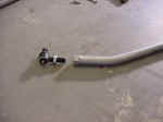 |
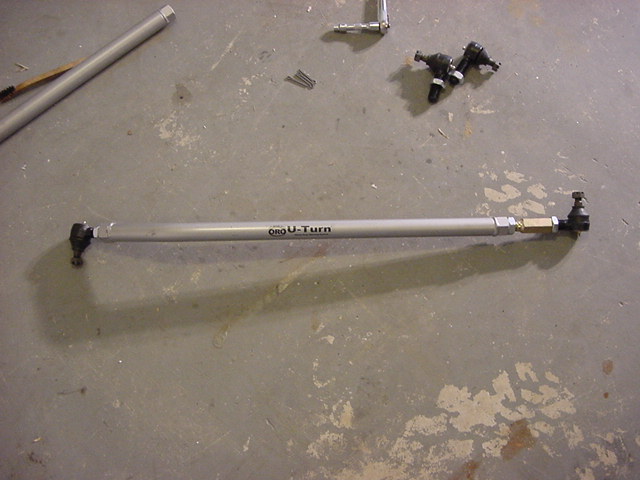
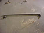
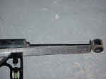
| 10.
Adjust the tie rod end until they are facing the opposite directions
. This is what the bar should look like. Short side down,
Long side Up. |
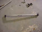 |
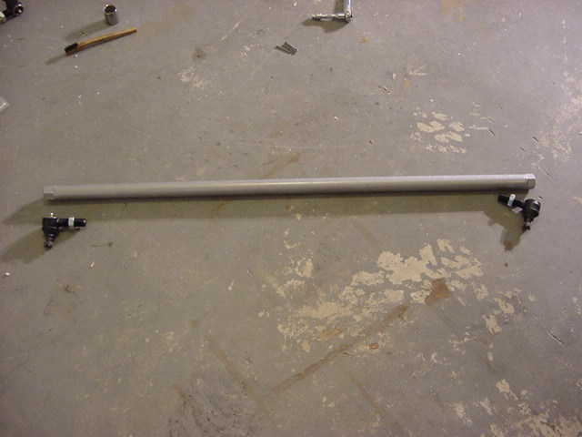
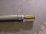
| 11. Screw in the remaining tie rod ends into the tie rod. You need
to set the the tie rod to 48" tie rod end center to tie rod end
center. It is simple to use the zerk fitting on each tie rod
to set this. Ensure that the tie rod ends are screwed in equally.
Estimate of 1/4" of thread behind the Jam Nuts. |
 |
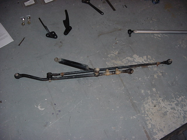
| 12. Remove the front drag link, tie rod, and steering stabilizer.
You may need to remove the tires. |
|
|
|
| 13. Remove the cotter pins from the castellated nuts on the two steering
knuckles, and the pitman arm. |
| 14. Loosen the castellated nuts, but do not remove them. Unscrew
the nuts until they are flush with the top of the threads. |
| 15. There are two ways to remove the tie rod ends from the knuckles and
the pitman arm. You can use a pickle fork to separate them.
Insert the pickle fork between the tie rod end and the mount, and
just pound away on the pickle fork until it separates them.
The other method is to hit the end of the steering knuckle right by
the tie rod end with a big hammer. A couple good hits and the
tie rod end drops out. With the pitman arm try to hit directly
towards the shaft, this will remove the give that occurs from hitting
it on the side. |
| 16. Once you have all the tie rod ends loose, remove the steering stabilizer
from the axle mount. You will need a 15mm socket, extension
and a 18mm combo wrench. |
 |
| 17. Now remove the entire steering assembly as one unit. If you
have an aftermarket steering stabilizer you will need to remove it
if it is one of those that can be used with the U-Turn steering. |
 |
| 18. Off Road Only U-Turn steering requires the use of the stock drag link.
So if you have a drop pitman arm installed you will need to remove
it and reinstall the stock pitman arm. This will requires a
32mm socket and a pitman arm puller. |
 |
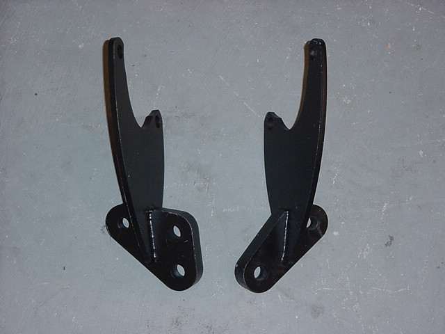
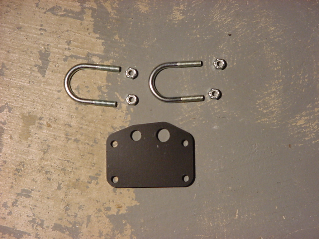
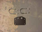
| 19. Assemble the parts you will need for mounting the hub assemblies.
The bracket with the 3 holes in it will mount to the passengers side
steering knuckle. |
|
|
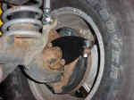
| 20. Working on one side at at time. Remove the forward and
top wheel bearing retaining bolts on each side; these will require
a 13mm 12point socket or a 13mm 12point box end wrench. Either
way they are difficult to remove. I used a cheater wrench to
help with a little extra torque. Once they break free they come
right out. |
|
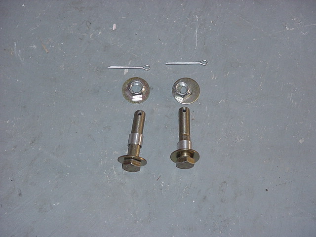
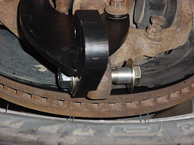
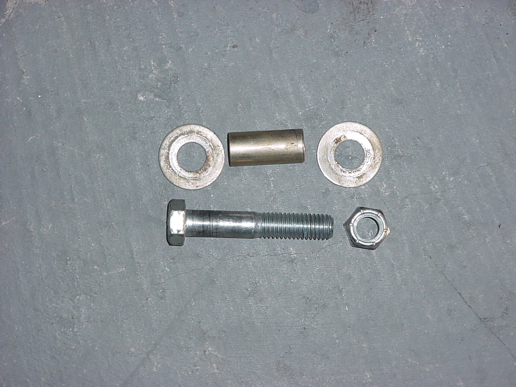
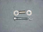
| 21. Locate the Į-20 grade 8 x 2.5” long
bolt with the cross drilled hole in the threaded end. This bolt should
have a top lock nut, 2 washers and an aluminum bushing. Remove the
nut and the first washer. This should leave the Bolt, a flat washer,
and the bushing on the bolt, in that order. |
|
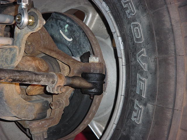
| 22. Place the hub assembly so that the non-tapered hole is positioned
over the OEM drag link attachment point. Insert the bolt/washer/bushing
assembly from the bottom. Place the washer and the nut on the top. |
 |
| 23. Install the two wheel bearing retaining bolts that you removed earlier.
Place a few drops of LockTite (recommended only if you wish to torque
these bolts once, if you wish to check the torque during vehicle maintenance,
do not locktite!) on the 2 wheel bearing retaining bolts and install.
Start the threads and tighten a couple of turns to ensure that they
are started properly. |
 |
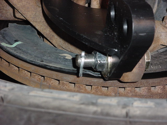
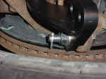
| 24. Push the Į-20 bolt and bushing assembly up into the taper, there should
be approximately 1/8” of the bushing remaining below the stock steering
knuckle. This is the allowance for crush, the bushing will swedge
into the taper providing a very tight, rigid placement of the bolt
in the tapered hole. When tightening this nut, hold the bolt to prevent
it from rotating, turning only the nut. This requires a 3/4"
Combo Wrench and a 3/4" deep well socket. |
|
| 25. Once the bushing is seated, tighten the wheel bearing bolts.
This will require a 13mm socket, or 13mm Combo wrench. |
 |
| 26. Torque the bolts on the brackets, then the 1/2-20 bolt, then install
the cotter pin on the 1/2"-20 bolt. This is just to retain
the nut if it were to ever back off that far. |
 |
| 27.
Install the drag link assembly. With a needle nose pliers or
similar small instrument, align the cotter pin holes in the tie rod
ends so that they are parallel with the axle. This will make
installing cotter pins easier. Insert tie rod end into the passenger
steering knuckle bracket and install castellated nut. |
 |
| 28. Insert opposite end into pitman arm. With lifted suspensions
you will be required to adjust the drag link length to center your
steering wheel. The initial setting on the drag link will closely
approximate the stock setup. Install castellated nut.
The U-Turn sticker should be facing forward and be basically parallel
to the ground. Bend in the bar pointed outwards. |
 |
| 29. Install the Tie Rod assembly. With
a needle nose pliers or similar small instrument, align the cotter
pin holes in the tie rod ends so that they are parallel with the axle.
This will make installing cotter pins easier. Make certain
that the right hand threaded tie rod end is on the passenger side.
This will make future adjustments easier. The rod should fall
right into place. The setting of 48" is close for both
stock and lifted heights. |
|
 |
| 30.
Tighten all of the castellated nuts, and take it for a slow test drive,
to get the feel for it, and to check the steering wheel position.
Adjust the drag link as necessary to center the steering wheel.
Recommend taking it in and getting an alignment.
3/4" Combo wrench or socket is needed for all the tie rod ends.
I used 2 adjustable wrench's to tighten all of the Jam nuts down. |
 |
| 31. Installing the steering stabilizer. The bracket comes with
2 different holes drilled in it to fit the above listed steering stabilizers.
The Monroe comes with a 1/2" stud that has a taper on it to attach
to the bracket. It does work, just doesn't look as nice.
I decided I would not use this stud. |
 |
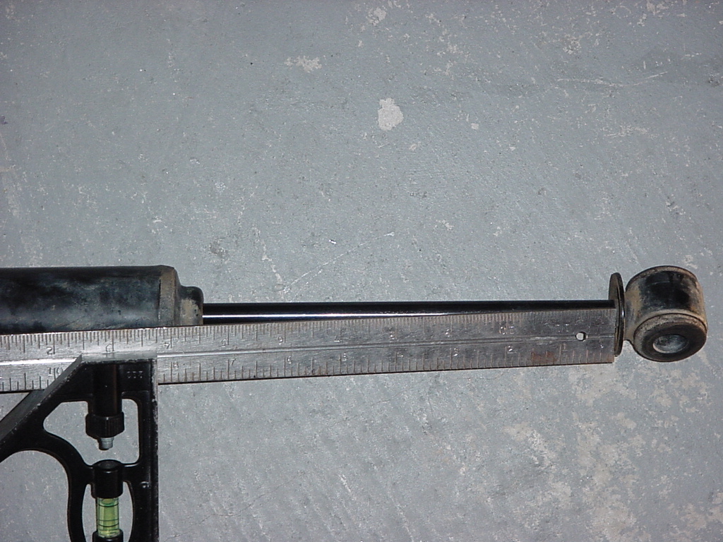
| 32. Now I am assuming that you have already centered the steering wheel
and that the vehicle drives straight. If not.... correct that
first. Measure the extended length of the shaft of the steering
stabilizer. This measurement should be close to 8" to allow
for a proper fit. Compress the stabilizer shaft to 1/2 of this
measurement. |
 |
| 33. Now bolt the steering stabilizer into the axle bracket with the factory
bolt. You will need an 18mm Combo Wrench, and a 15mm Socket
on an extension. |
 |
| 34. With the stabilizer bolted in you can see where you will need to position
the bracket on the drag link. |
 |
| 35. Check the fit of the bracket first. Since I was using the 1/2"
hole in the bracket I needed to position the bracket so nothing would
interfere with the movement during turning. As you can see having
the hole farthest away from the pitman arm does not work since the
u-bolts interfere with the stabilizer. You will need a 1/2"
Deep well or a 1/2" Combo Wrench to tighten the nuts for the
U-Bolts. |
|
 |
| 36. Now since I decided not to use the stud that came with the Monroe
Stabilizer, I need to figure out how to mount it. This was answered
by "Mac" at www.macs4x4products.com . He utilized a 1/2" bolt, nut and 2 washers to mount his.
Here is what you will need exactly. (1) 1/2" x 3"
grade 5 or 8 bolt, (2) 1/2" washers, (1) 1/2" nylon lock
nut, and (1) spacer from a shock eye. If you have installed
AiROCK the spacer from the shock eyes that were pressed out during
installation of the Bar Pin Eliminators works well. (I have
a couple from my Grand Cherokee that worked). I inserted the
spacer into the rod end bushing of the stabilizer. I currently
have a grade 5 bolt installed. This required a 3/4" socket
and 3/4" Combo Wrench. |
 |
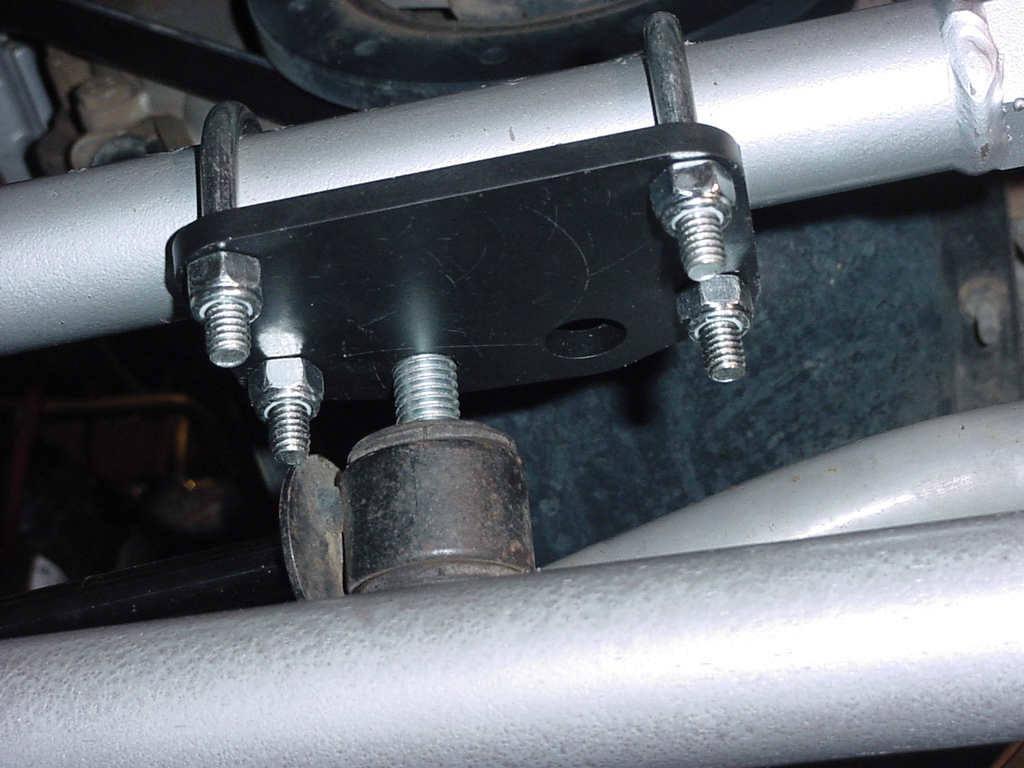
| 37. Now position the the bracket onto the drag link. The bracket
should be on the bottom side and angled up towards the rear.
I decided to keep the rod end bushing at a 90 degree angle to the
axle end bushing. This should allow for movement in all directions.
I then bolted the stabilizer to the bracket and watched as a friend
turned the steering both directions. You want to make certain
that there is no contact. |
 |
 |
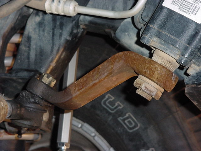
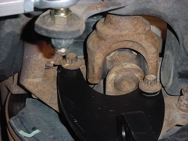
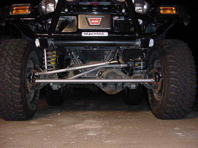
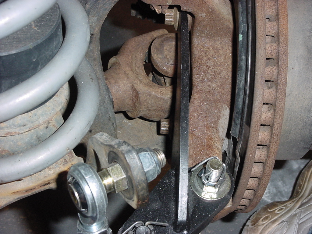
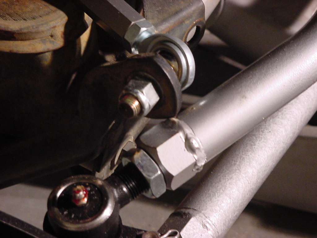
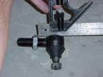
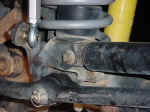
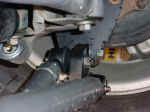
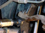
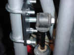
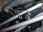
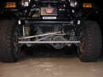
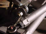
| Here
it is installed. The stabilizer was added later on than this
picture. |
 |
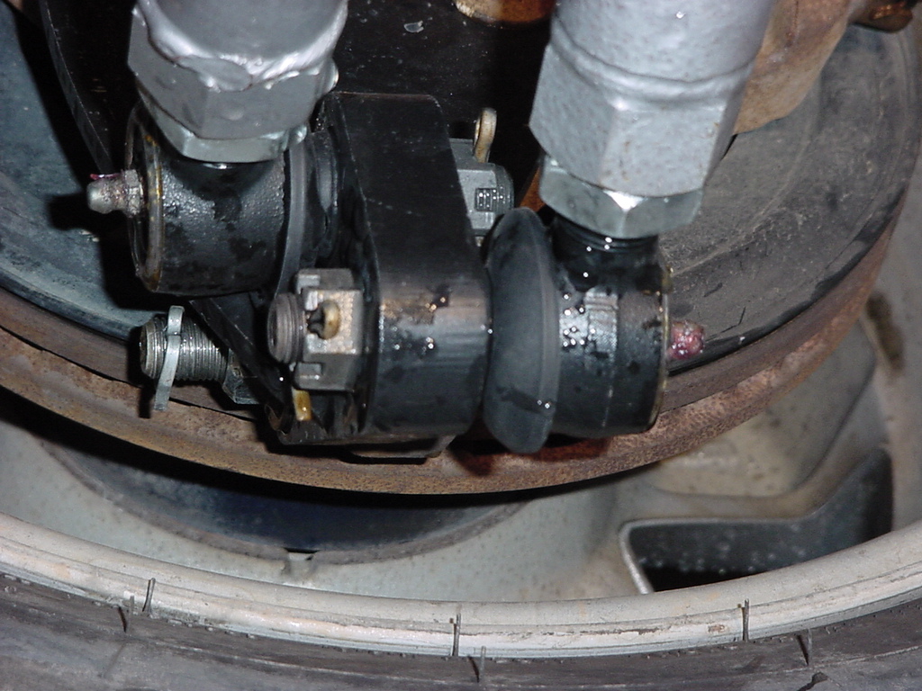
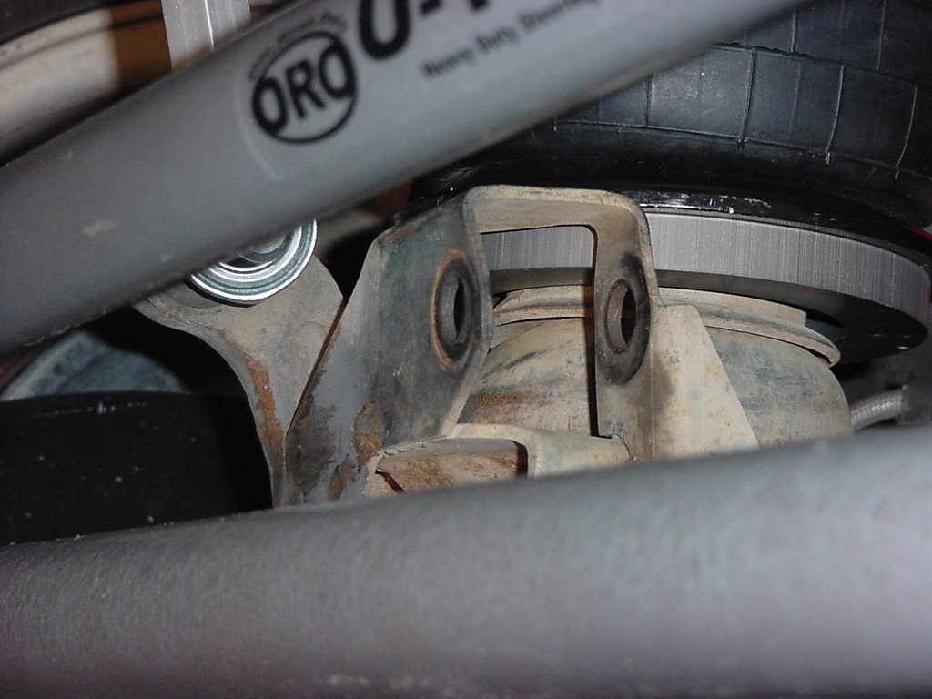
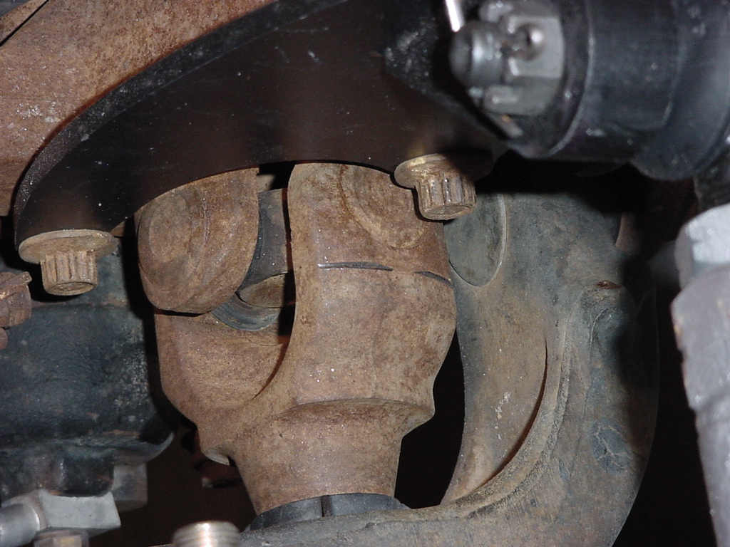
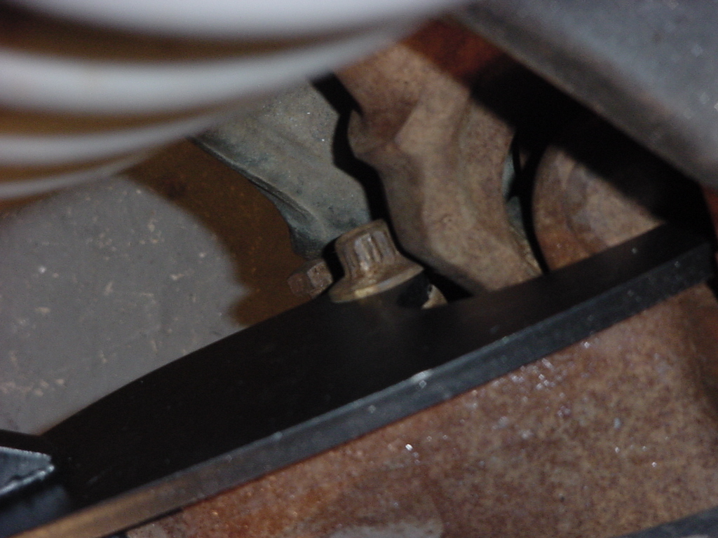
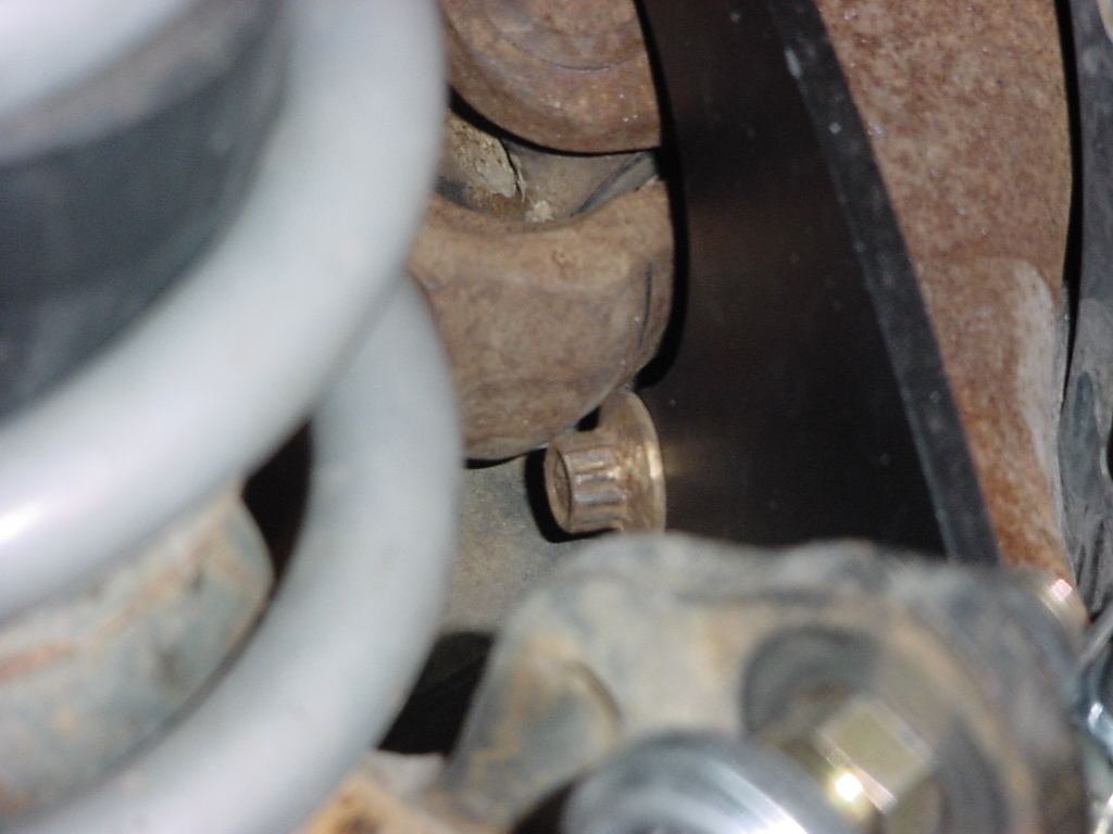
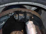
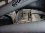
| One
thing that you will need to check after driving it briefly is if the
lower wheel bearing bolts rub on the front axle yokes. It is
the flange on the bolt head that rubs, not the ORO bracket.
A couple of Jeeps have had this problem and the initial thoughts are
that some Jeeps have steering stops that are just slightly shorter
than others. On my Jeep I have always noticed that I can turn
sharper than others, and that I can still rub my Lower Control Arms
even with the tires spaced out. While others with similar setup
cannot. |
|
|
|
|
|
|
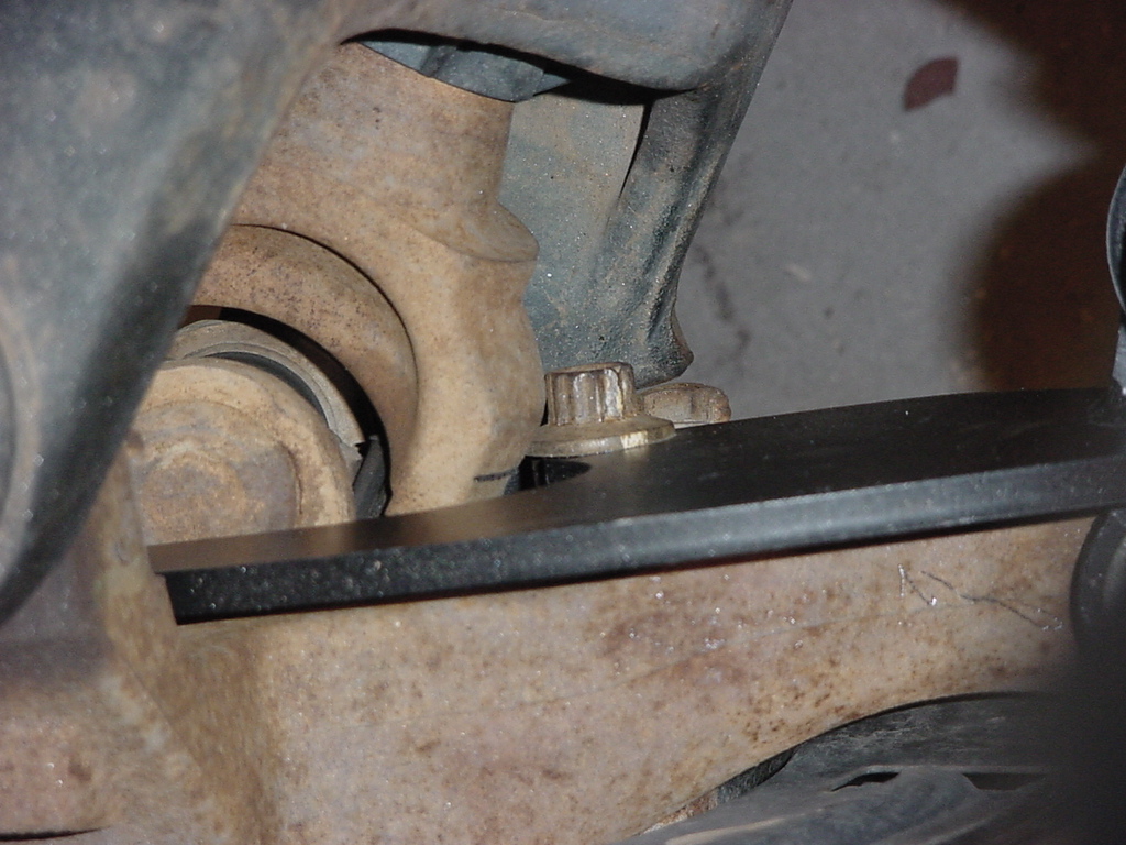
| The
simple solution to this is to install a washer on the steering stops
to solve this problem. Since I can already turn sharper than
others, I don't feel that I will be losing much with limiting a little
more. |
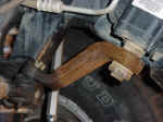
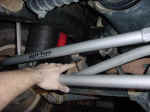
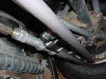
| At
max flex I can just rub the weld on the weld on the drag link against
the front anti-sway bar axle bracket. |
 |
|
Some Notes from Off Road
Only
Driving.
The toe setting plays a big factor in how it drives.
Excessive toe in: A steering adjusted
with too much toe in will be quick over center, twitchy, almost
impossible to keep going straight on rough roads.
Excessive toe out: A steering adjusted
with too much toe out will be slow to respond to steering input
and may also deliver an over steer condition once it does respond.
Our findings,
35-37” tires toe set at zero to + 1/32 (1/16 toe in)
31-33” tires toe set at +1/32 to +1/16 (1/16 to 1/8 toe in)
Settings may be affected by tire pressure and other
variables; each vehicle should be adjusted to the best drivability.
500 Mile check and then every 3000 miles after that Remove the cotter pins and recheck the torque on the
Į-20 grade 8 bolts. Reinstall cotter pins.
Check torque on the 12point 13mm wheel bearing bolts. ***Only if
not lock-tited! ***
Check jam nuts to ensure they remain tight.
|