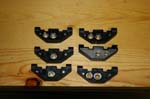
Brad being the ever ingenious individual needed some power in the rear of his JK, so he devised these ingenious panels to mount to each side and give you not only 12vdc plugs, but 110vac plugs via a 400watt power inverter. His panels for his personal JK have additional openings cut for video feeds and USB ports the last time I saw them. I was able to get a set of panels to start work on my JK. A few modifications have been done to my panels to suit my needs. The nice thing is there is plenty of space to include later upgrades. What I have is the initial prototype set, a complete set with power outlets, inverter and wiring is rumored to be offered later.
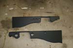
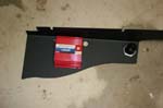
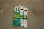
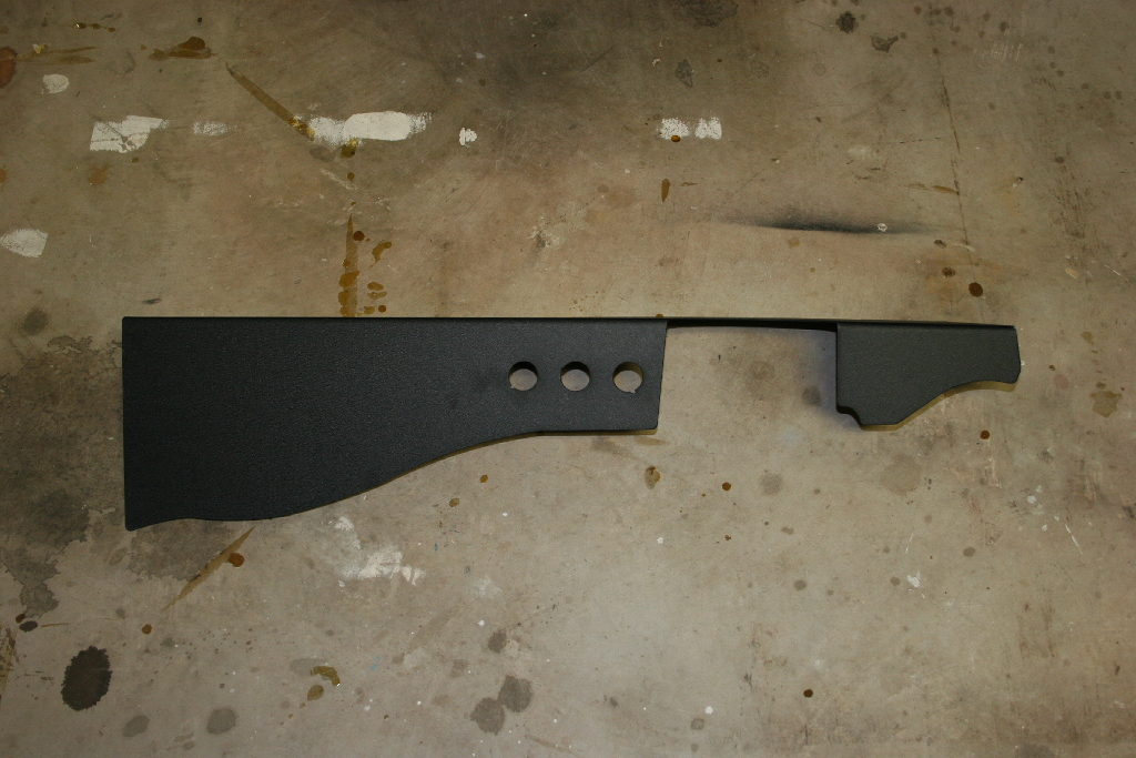
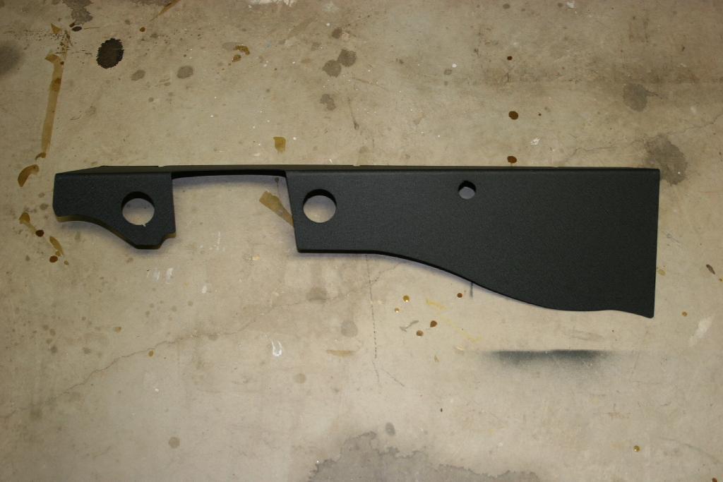
| The basic panel set. |
 |
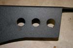
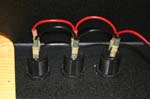
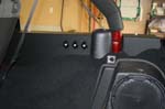
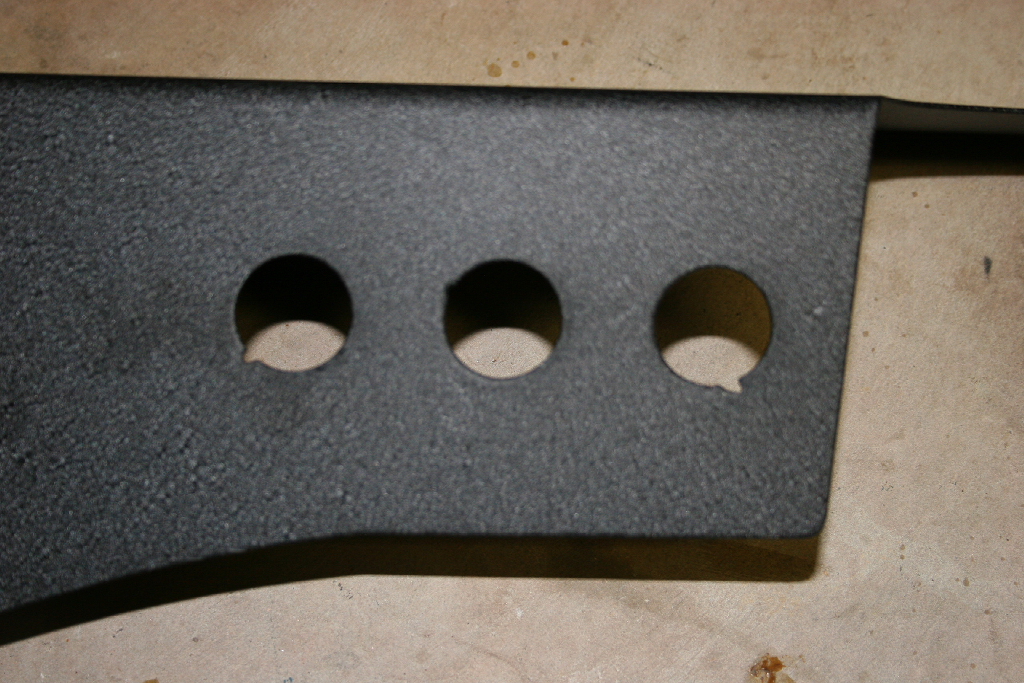
| Passenger side panel has openings for three 12vdc power outlets. This side is the most modifiable of the two. I intend to have a set of video and stereo outlets here being fed by my 6disc dvd player. I will also be modifying the panel to have individual switch's for the power outlets. |
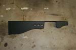 |
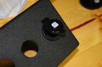
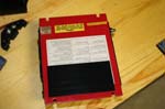
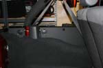
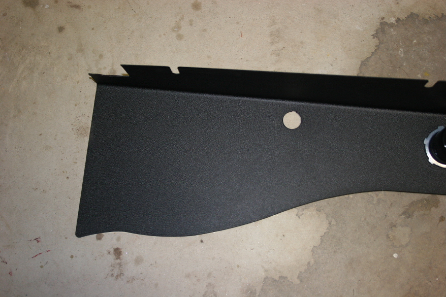
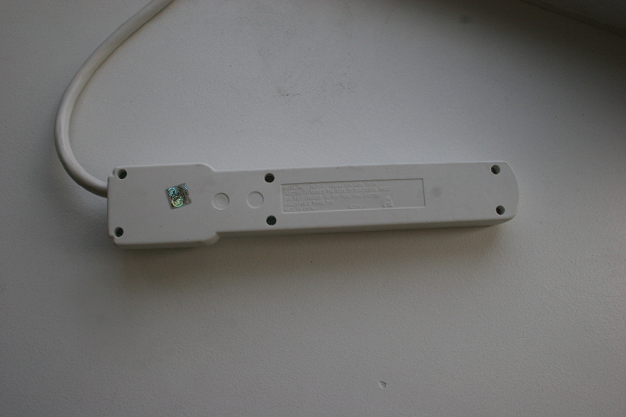
| Driver side panel has openings for the two 110vac plugs and a finger hole to turn on the 400 watt power inverter. |
 |
| |
| 12vdc plug installation: |
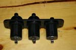
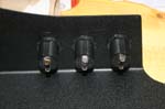
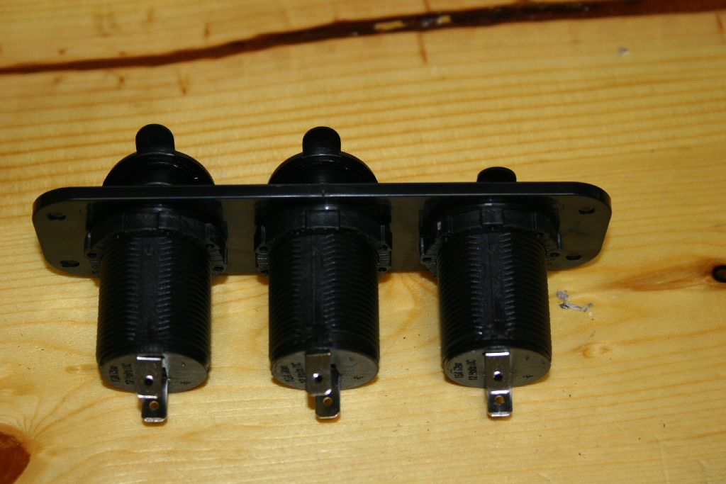
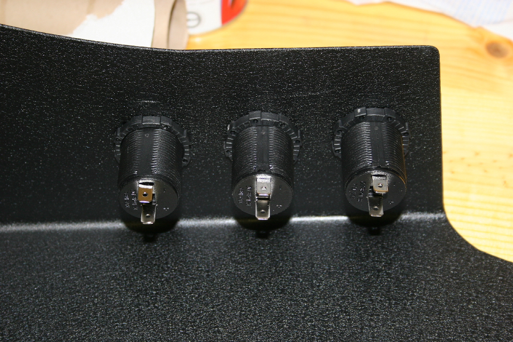
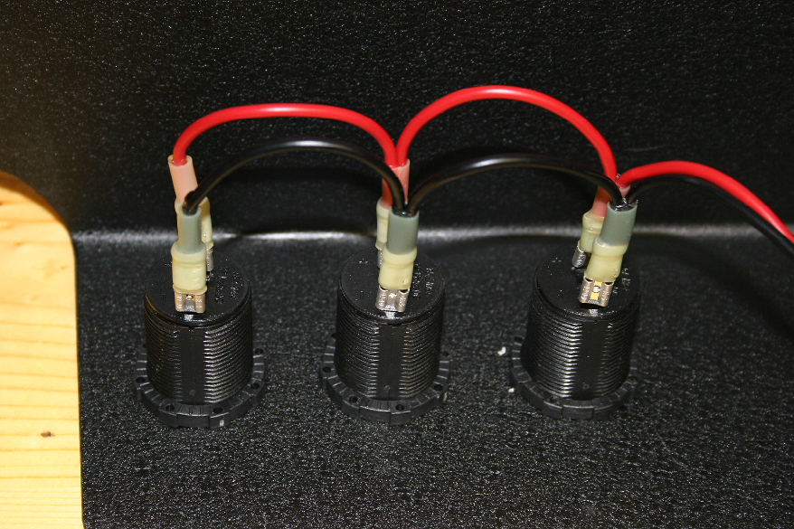
| The three 12vdc power outlets will go in these three holes on the passenger side panel. |
 |
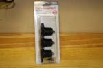
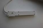
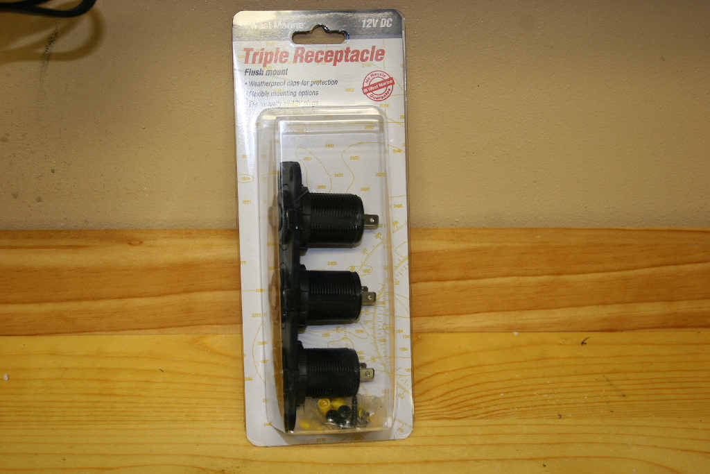
| I picked up a three outlet strip from my local West Marine for $20. This was cheaper than buying individual ones. |
 |
 |
 |
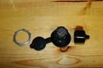
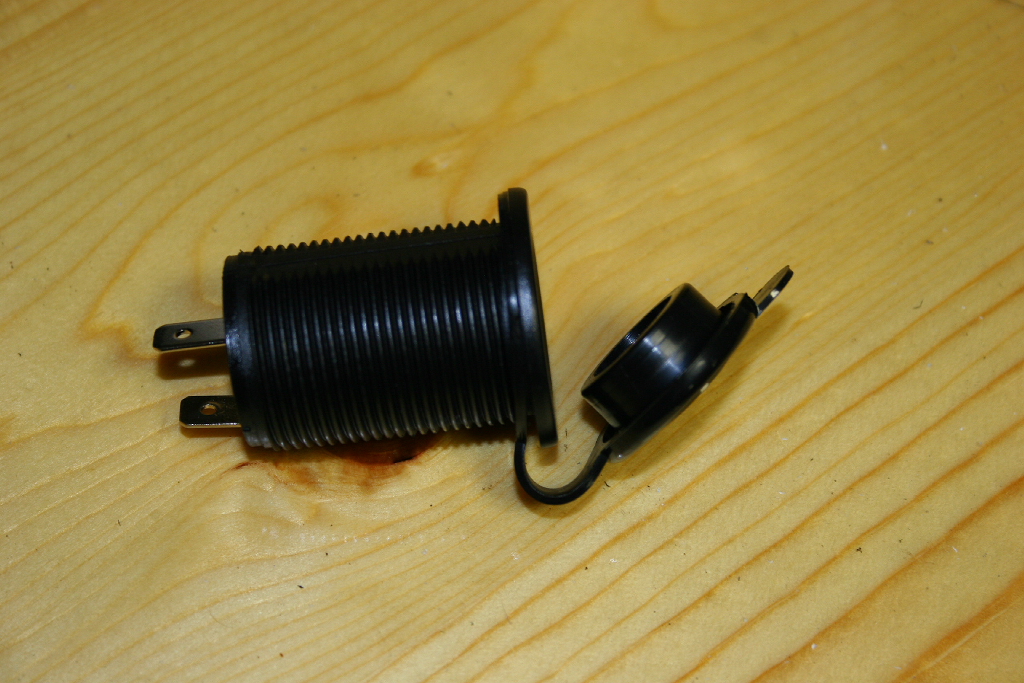
| Disassemble the power outlets from their bracket by unscrewing the locking ring, removing the rubber seal cap, and pulling the outlet out of the bracket. |
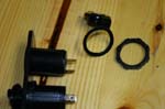 |
| Reinstall the rubber seal cap on the outlet. |
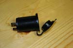 |
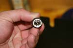
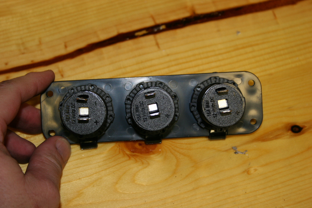
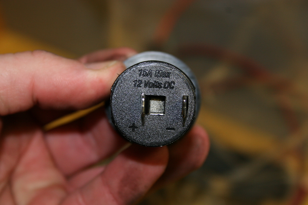
| The back side of the power outlet is marked with a + and - to indicate which terminals need to be wired. It also has a warning about max power being 15amps. |
 |
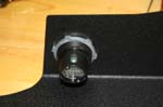
| Install the outlet into the power panel. This is a precise fit, so take your time and don't cock the outlet in the panel, it won't go in. |
 |
Position the outlets so that the + and -'s line up in a row. I positioned the + terminal up so that I could wire in power switch's later. |
 |
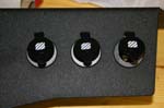
| Installed. |
 |
 |
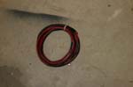
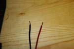
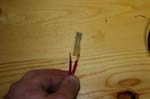
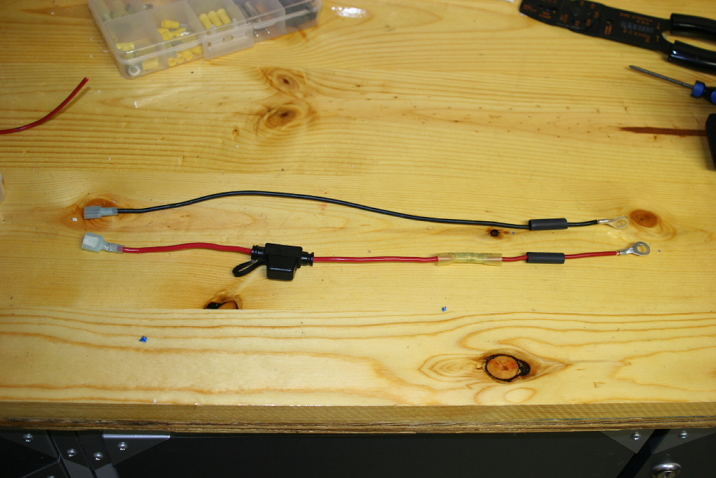
| I had a coil of 14gauge wire laying around from the power inverter project, or something else I don't remember since I had 2 coils. You will need enough cable to go to either the battery, or across behind the back seats to the power inverter on the other side. I choose to go to the power inverter. |
 |
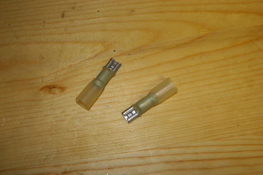
| Strip the end of the wires and crimp a connector onto the exposed ends. I typically use heatshrink connectors to form a good seal. |
 |
 |
 |
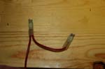
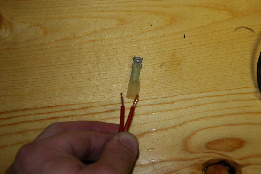
| Now clip the connectors onto the back of one outlet and measure to the next with the wire. This will give you a length for your next wire. |
 |
| Cut the wire and strip the ends off of both sides. Twist the wires together and crimp a connector onto the exposed ends. |
 |
 |
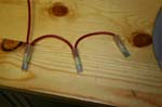
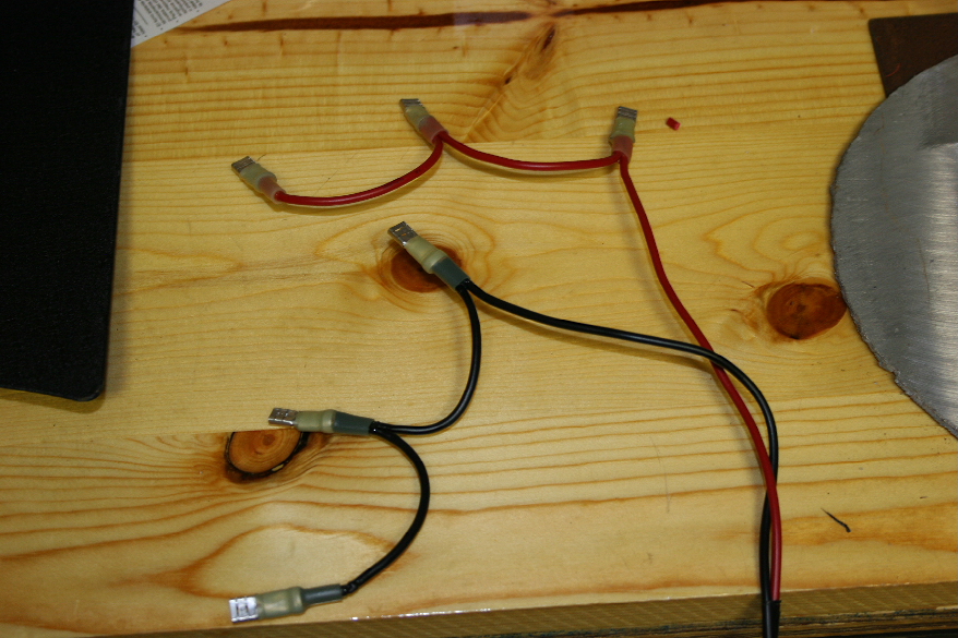
| Repeat the above steps until you have two harness with three connectors. Once you have them completed, heat shrink the connectors to form a nice seal on the wires. |
 |
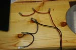 |
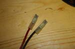
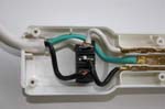
| Attach the harness to the power outlets. Black to negative and Red to positive. |
 |
| You will need to place the panel in the jeep so that you can route the wires down and underneath the carpet below the rear seats. |
| |
| 110vac plug and power inverter installation: |
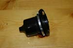
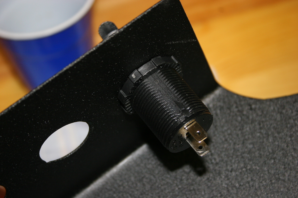
| The two 110vac plugs go in the two large holes on the drive side panel. |
 |
| These plugs come from Marineco and are designed for marine use, so should be just fine in the back of the jeep. |
 |
 |
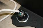
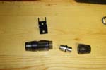
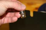
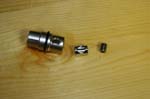
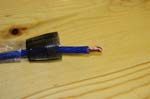
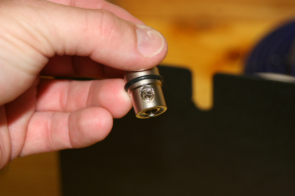
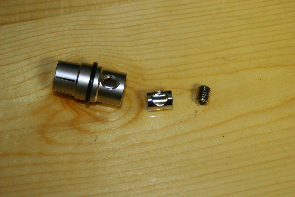
| Disassemble the plug by removing the lock ring and the rubber seal cap from the back. The plug is a standard wiring setup. |
 |
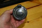
| Insert the plug through the panel and install the lock ring behind it. |
 |
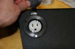
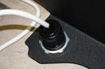
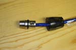
| Installed |
 |
 |
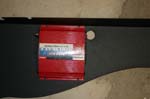
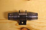
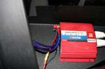
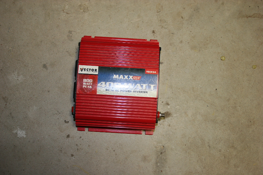
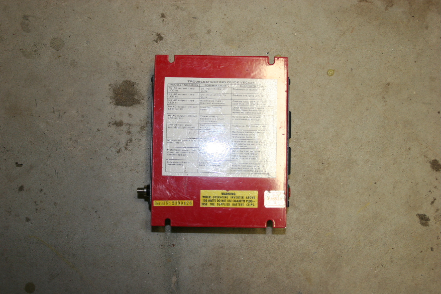
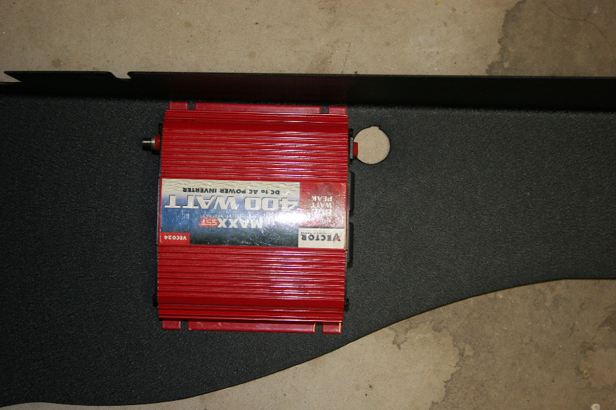
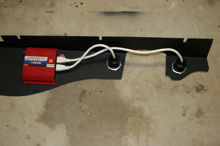
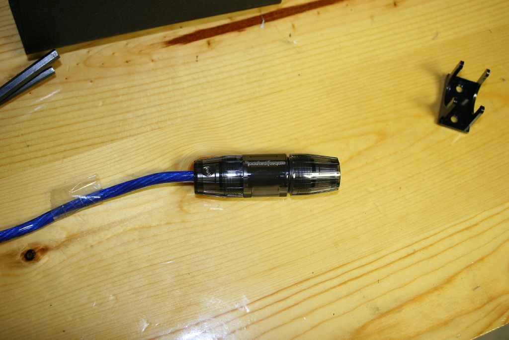
| I used a Vector 400watt power inverter on this project. The on/off switch lines up with the predrilled hole in Kilby's power panels. I would have liked to mount a new black & decker 400watt power inverter with the 5vdc USB power supply on it, but the switch was located on the top center so posed a problem turning it on and off. |
 |
| Clean off the bottom of the power inverter, and the back side of the power panel with alcohol. |
 |
 |
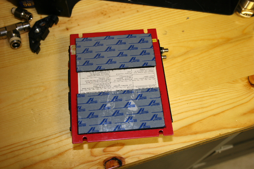
| Attatch Industrial strenght velcro strips to the back of the power inverter. Leave the tape on the opposite side for now. |
 |
 |
| Check the positioning of the power inverter on the back of the panel. |
 |
 |
| Remove the tape from the velcro and press the inverter onto the back of the power panel. |
 |
 |
| Now measure from the plugs on the power panel to the back of the 110vac plugs installed in the power panel. This will give you an idea of how much cable you will need to wire up your outlets. I didn't envision needing more than a 15amp load on each outlet, so I would only need a 14ga cord. |
 |
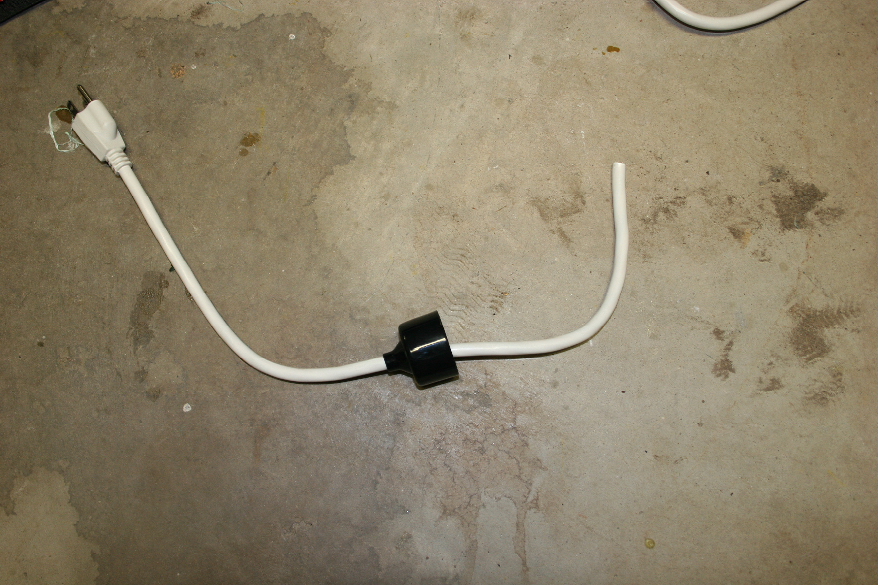
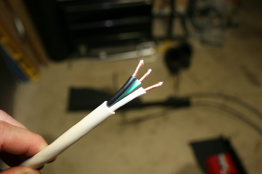
| I went looking at lowes for a power cord, but after seeing the price tag and realizing I really didn't need 10ft of cord I wanted to come up with a different plan than spending $24. I just happened to look down and realize that the power strips have the same gauge cord that I was looking for. Even better was the 3ft two pack for $5. To bad they were in white. |
 |
| Disassemble the power strips to remove the cords. Simply unscrew the back and cut the wires inside, or just cut the cord off at the base of the outlet strip. |
 |
 |
 |
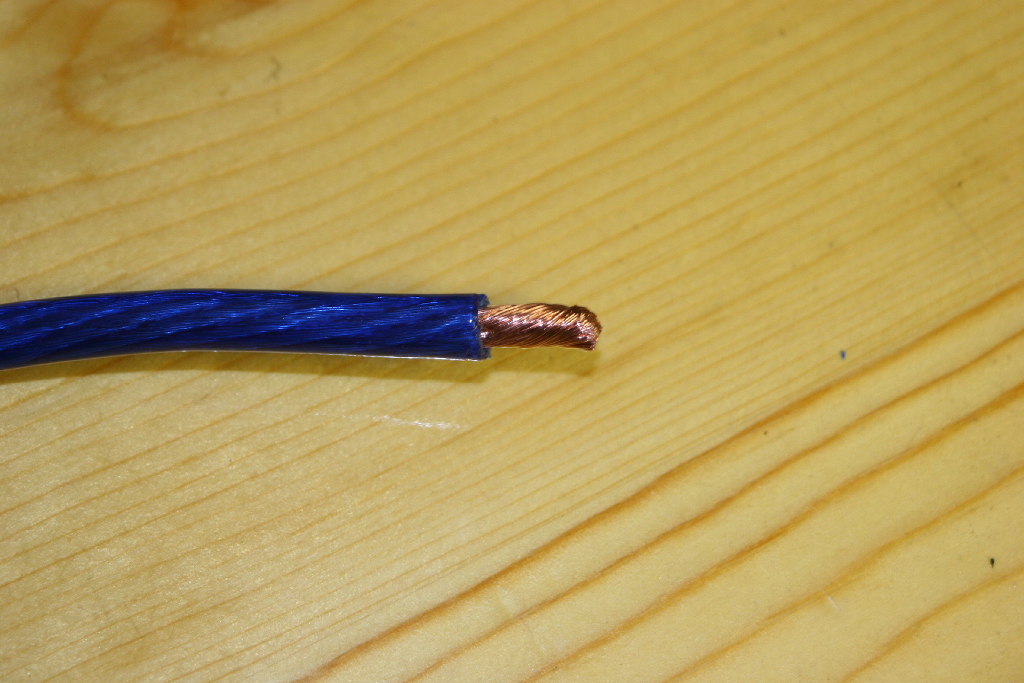
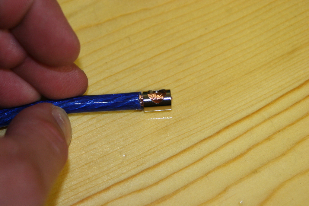
| Slip the rubber seal cup over the wire. It is easier to do with the wires cut flush than with the wires stripped. |
 |
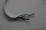
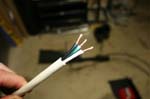
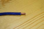
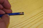
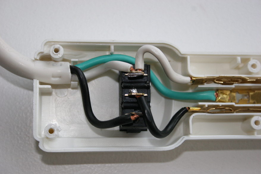
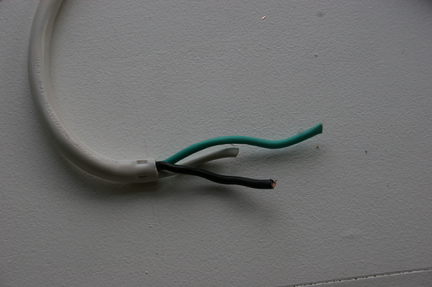
| Strip the insulation back from the three wires about 1 1/2". Strip the wires about 1/2". The outlet is wired simply. Green to ground, white to silver, and black to black. I checked the wiring with a simple outlet tester that I had when I was working on the house wiring. |
 |
 |
| Slip the rubber seal over the end of the outlet. |
 |
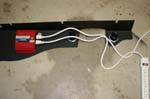
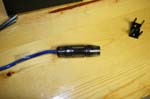
| The nearly completed assembly. I may use some stick on clips to hold the wires in position, but I will have to check after I install it in the Jeep. |
 |
| |
| Electrical Connections: |
| Route the 12vdc wire harness from the passenger side underneath the carpets to the passenger side. |
|
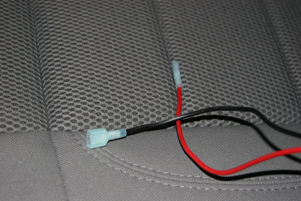
| I needed to make a pigtail for the 12vdc outlets. I figured that it would be easier than trying to hook up a wire with the minimum space behind the panel. |
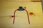
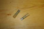
Mini Fuse holder
|
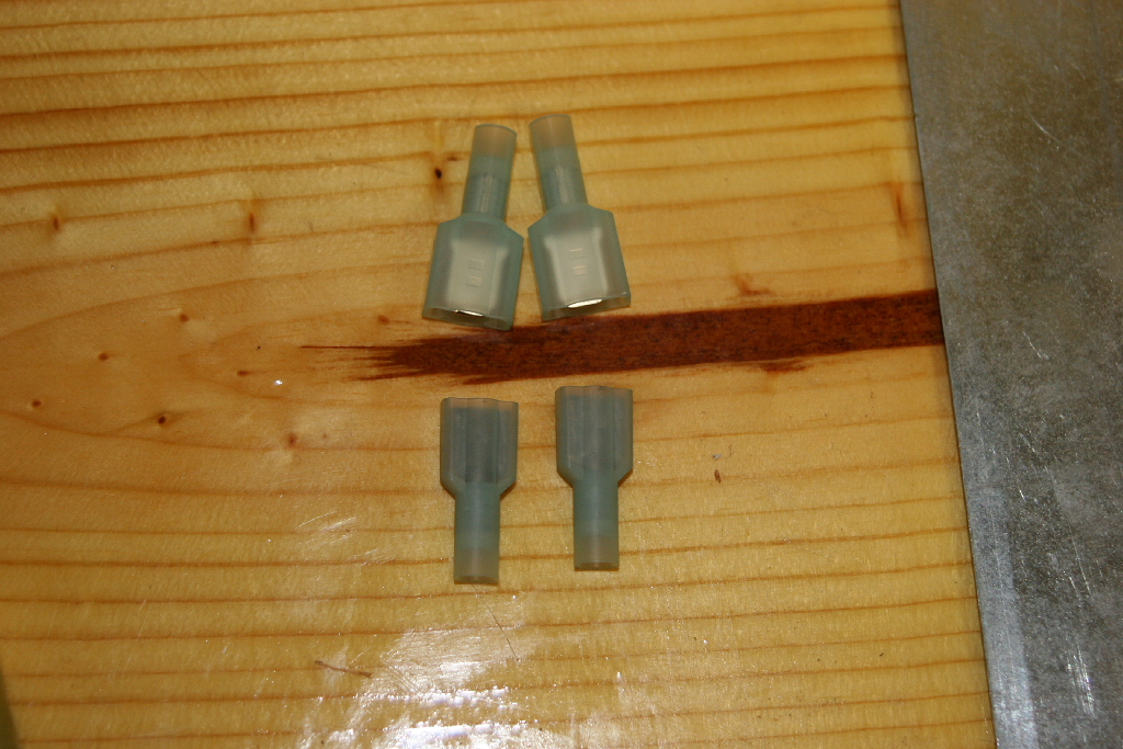
Spade connectors
|
Ring Terminals, 12gauge primary wire (red and black) and Heat Shrink Tubing |
| Cut a 12" long piece of the black primary wire. Place a piece of heat shrink tubing over each end. Crimp a ring terminal to one end of the black primary wire and one end of the mini fuse holder. Seal with heat shrink tubing. |
 |
| Measure the lenght of wire on the mini fuse holder and cut a piece of red primary wire long enough to equal the length of the black primary wire. Use a buttsplice or solder the red ends together. |
|
| Crimp a spade terminal to the end of the red and black primary wires. This will mate up with the wires that were run under the carpet earlier. I choose to crimp a male and female end onto the pigtail. Just a personal preference to keep the wires from getting crossed. |
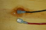 |
| Completed pigtail. |
 |
| Crimp the remaining spade connectors onto the wires from the 12vdc outlets. If you do it like I did you need to make sure you crimp the right connectors to the right wires so that they will match polarity, or have an extra set of connectors so that you can redo this step. Hint... |
 |
| |
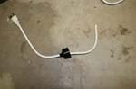
| Now to provide power from the battery to the inverter. I needed about 40 feet of cable to do this along with a good fuse holder. I searched through my drawers and found a amplifier hook up kit that had about 40 feet of #8 gauge wire and a few other small pieces of #8 wire. I stopped in the local best buy and picked up a fuse holder, some fuses and a set of ring terminals. |
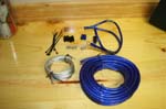 |
 |
 |
 |
 |
| I started at the battery looking for a good location to mount the fuse. There was as short piece of wire used for the battery to fuse hook up. You want to mount your fuse as close to the source as possible. |
 |
 |
| I originally wanted to mount the fuse right along the hood line, but the fuse was to large and would have gotten crushed by the hood. The wire is fine. |
 |
 |
| I ended up mounting the fuse right in front of the battery on the plastic support. |
 |
 |
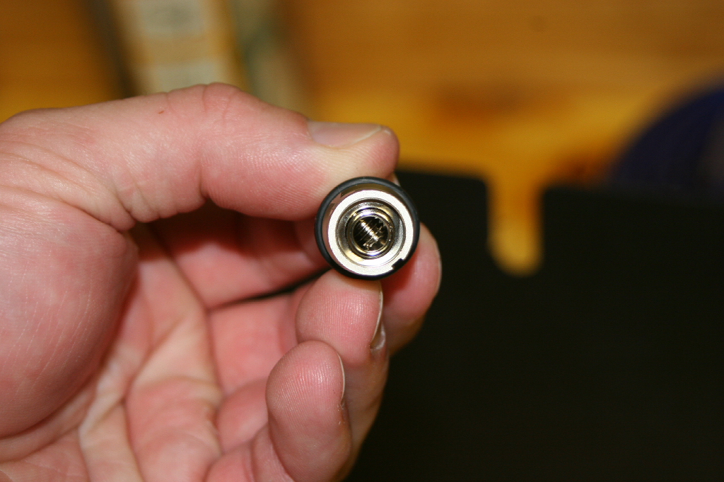
| Dissassemble one side of the fuse holder so that you can attatch it to the power cable. |
 |
| Remove the set screw and insert from the end of the fuse holder. The is designed to accept either #8 or #4 gauge wire. You need the insert for the #8. |
 |
 |
 |
| Measure back the length of the insert and strip the wire. Do a quick test fit. |
 |
 |
| Slide the cover for the fuse holder over the wire, and place the insert over the stripped end. |
 |
|
| Insert the insert into the end of the fuse holder and reinstall the allen screw. Reinstall the end into the fuse holder. |
 |
 |
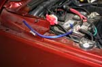
| I took the full length of the #8 gauge wire and doubled it over. I then adjusted the length of the ends to compensate for the lenght of the fuse holder and wire end. Back by the loop, mark the long side of the wire so that you know this is the negative. Reversing polarity to the power inverter is not a healthy thing to do to it. |
 |
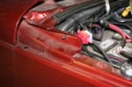
| Remove the end cap for the dash on the passenger side. |
 |
 |
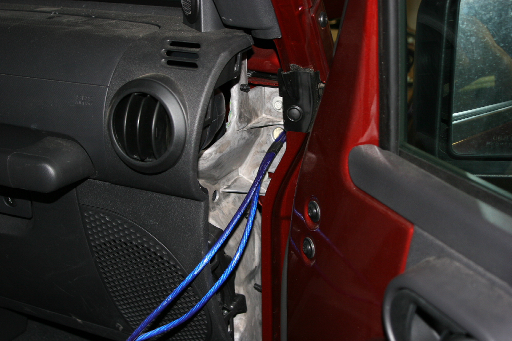
| There is a foam filled hole that goes through the firewall and underneath the edge of the cowl. I poked a hole through it and fed a mechanical finger through it to grab the wire from the other side. You can do this with one person (roll down the window), but two makes it easier. |
 |
 |
| Pull the wires through the firewall and into the engine compartment. I pulled enough so that the shorter side would make it to the location of the fuse holder. |
 |
 |
| Remove the three push fasteners and pull out the end underneath the dash. The end has 2 push fitting installed underneath that may or may not come out of the body. (Pull them out) |
 |
 |
 |
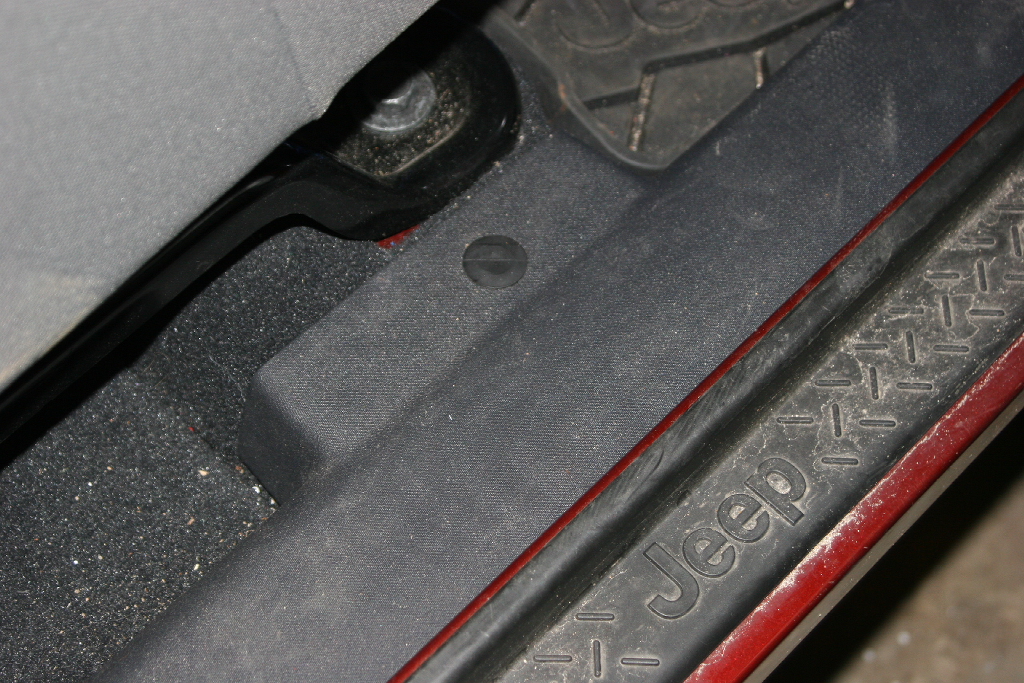
| Route the wire down the side of the dash and then along the rocker panel and finally across under the rear carpet. |
 |
 |
 |
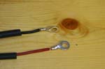
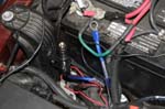
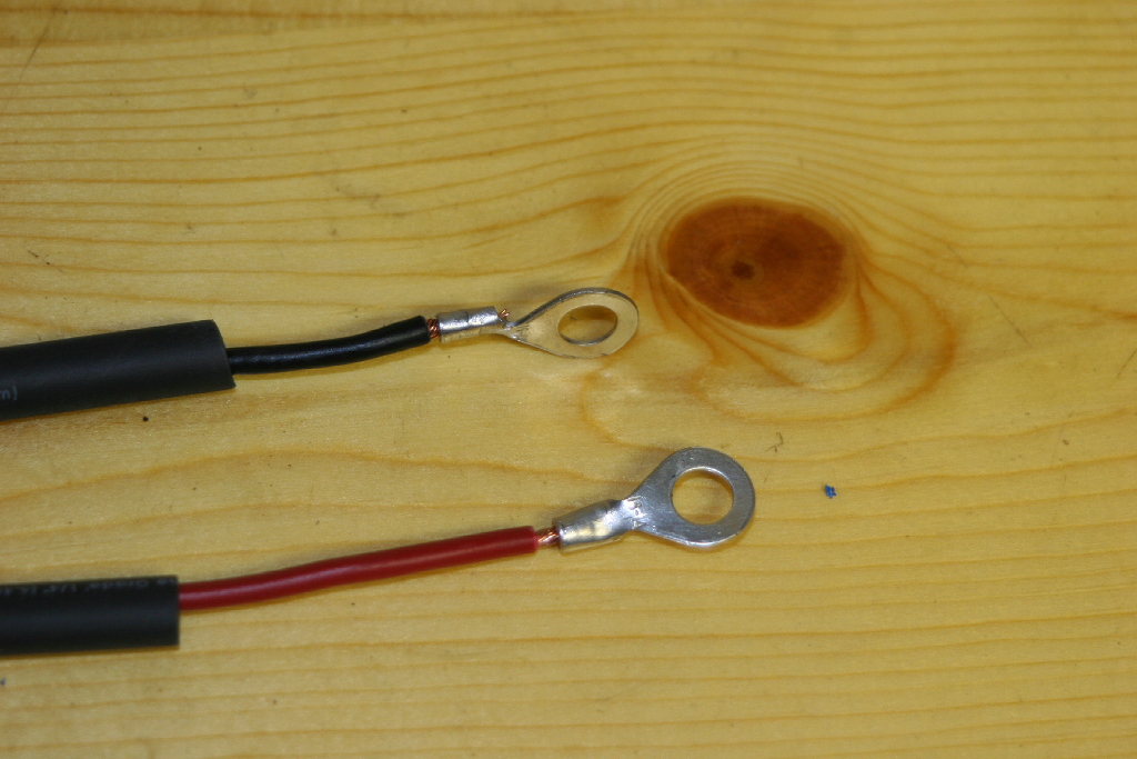
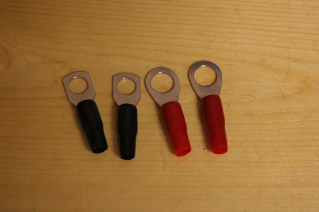
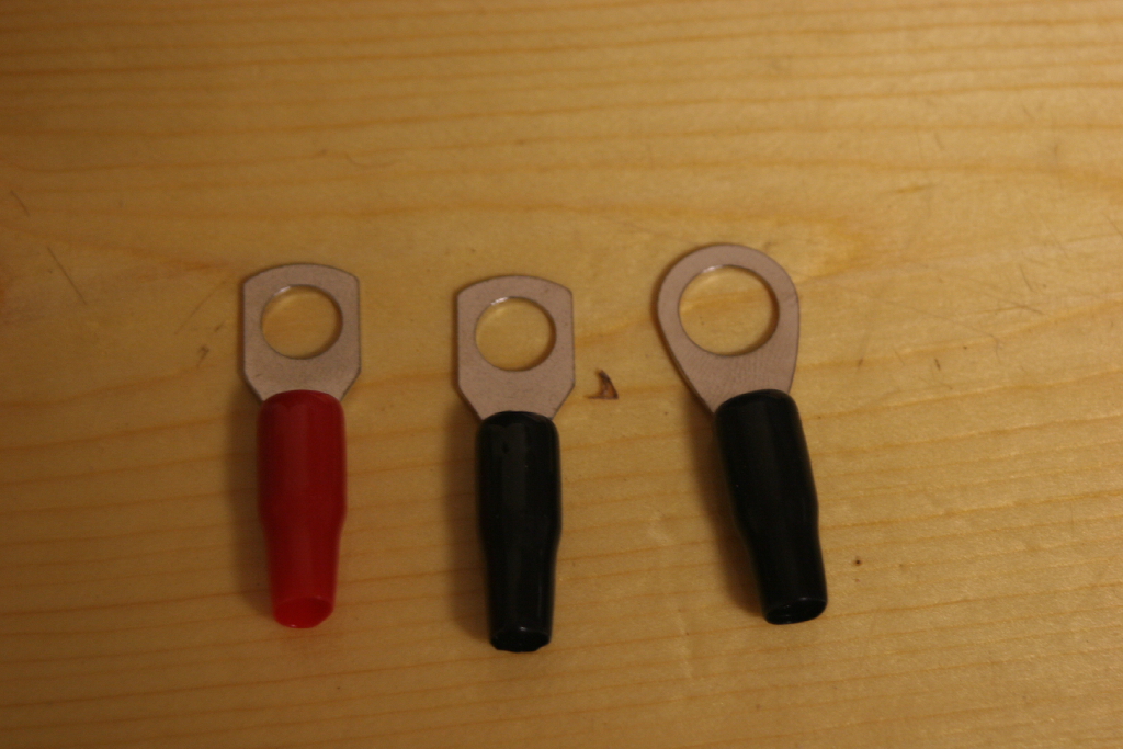
| The set of ring terminals comes with 2 large and 2 small ring terminals. I needed to use 2 small and 1 large, so I swaped out a red and black rubber end. |
 |
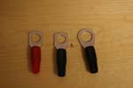 |
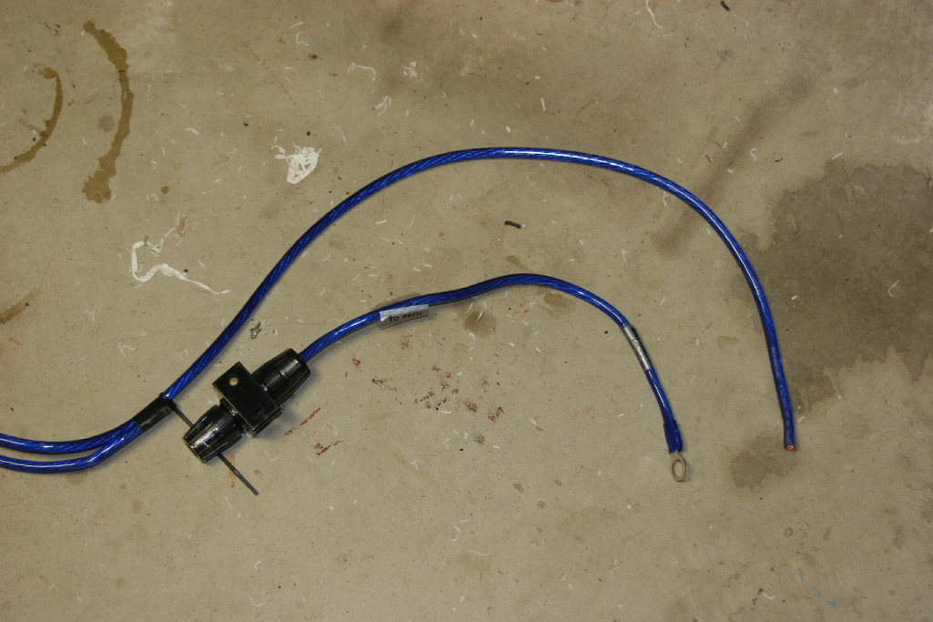
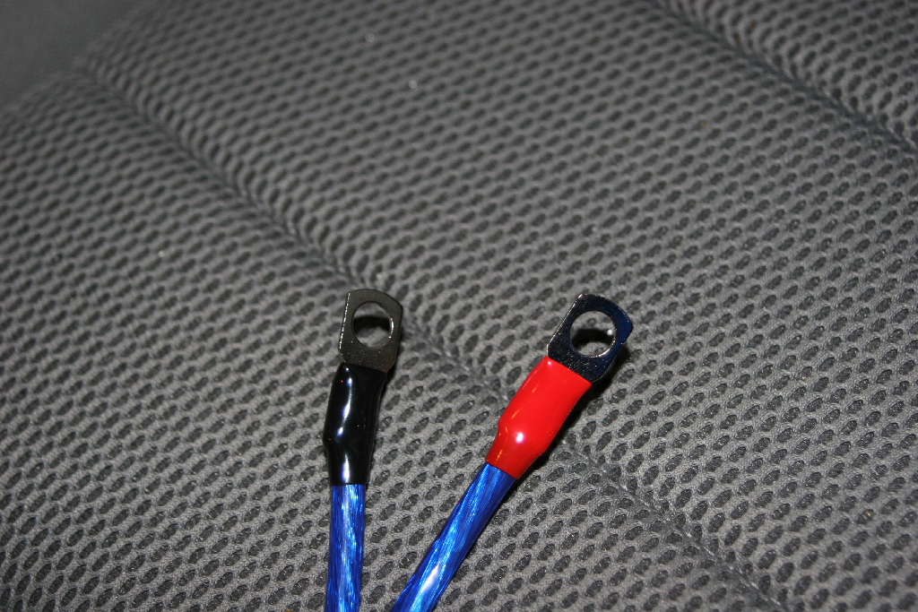
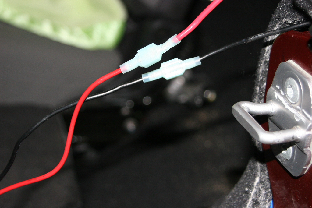
| Cut the end of the wire and crimp on the two small ring terminals. Make sure that the black is negative, and the red is positive. Do not reverse the polarity, power inverters do not like this. |
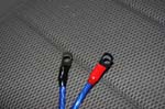 |
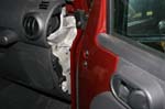
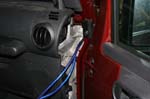
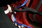
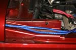
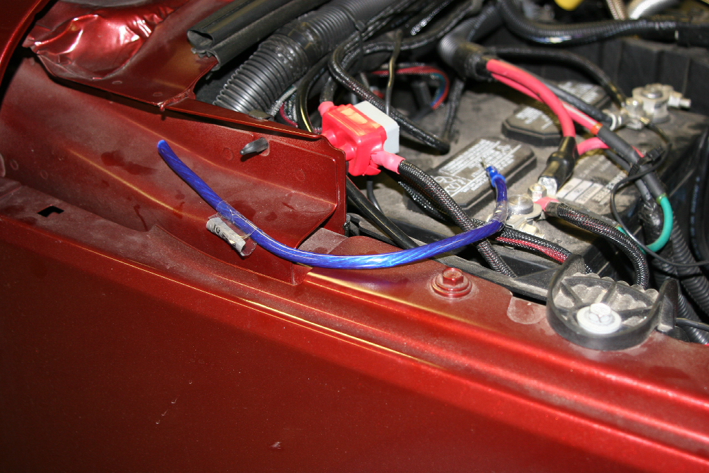
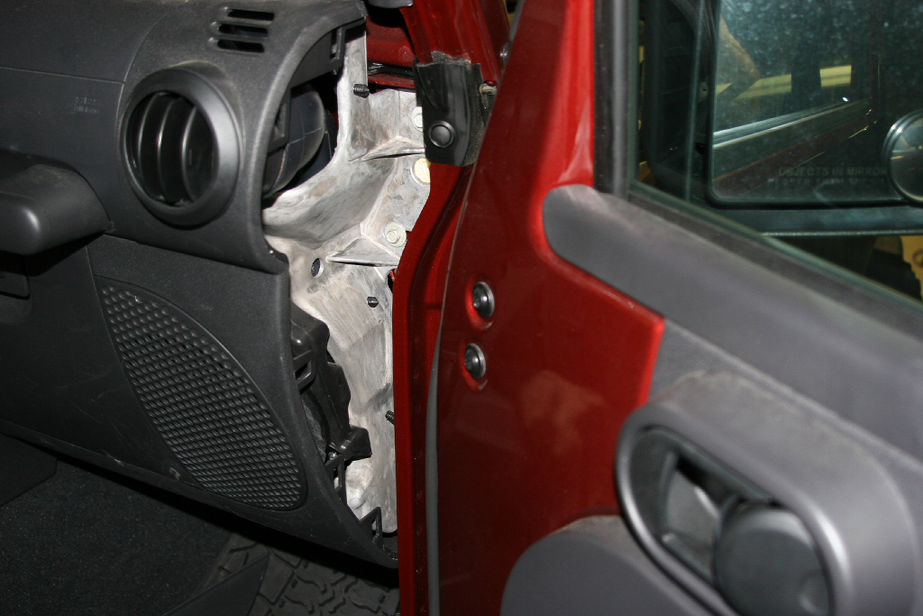
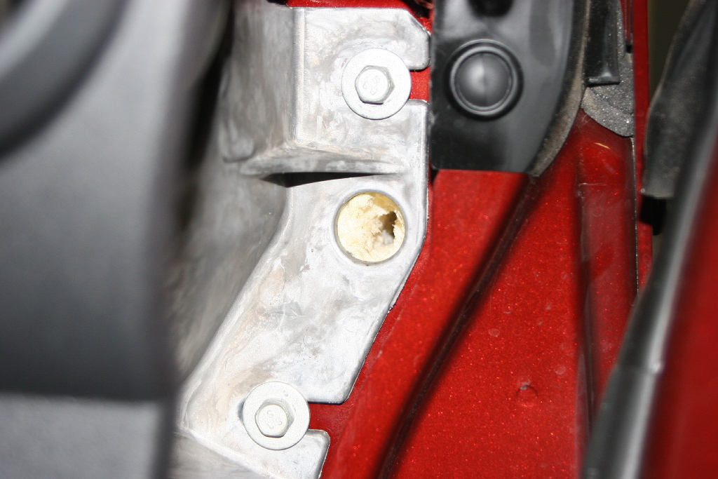
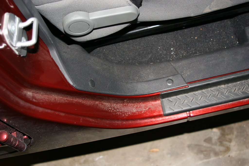
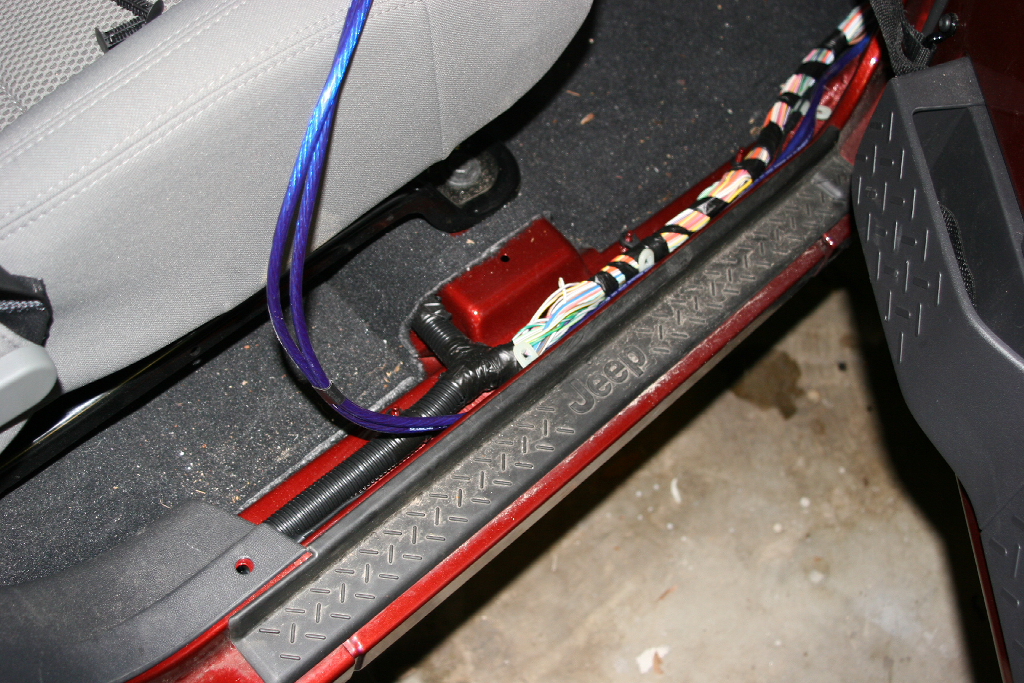
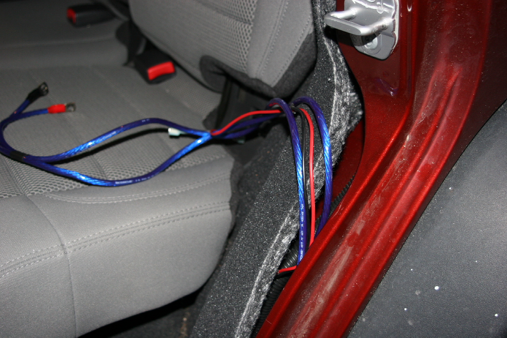
| Pull the carpet away from the side of the body and route your wires up to the top. The will tuck in behind the door latch reinforcement later. |
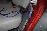 |
 |
| Connect the red and black leads to the power inverter. |
 |
 |
 |
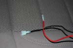
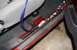
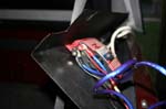
| Connect the 12vdc leads and install a 15amp mini fuse in the holder. Tuck all the wires behind the carpet. |
 |
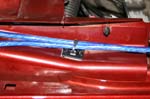
 |
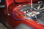
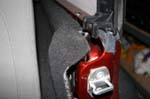
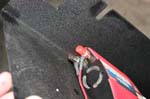
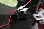
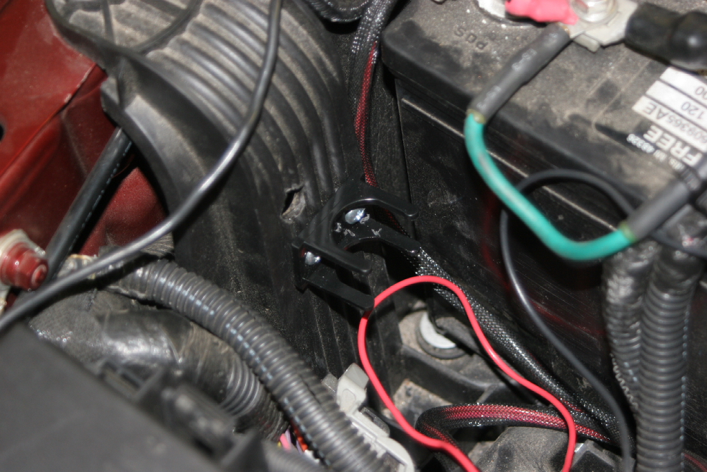
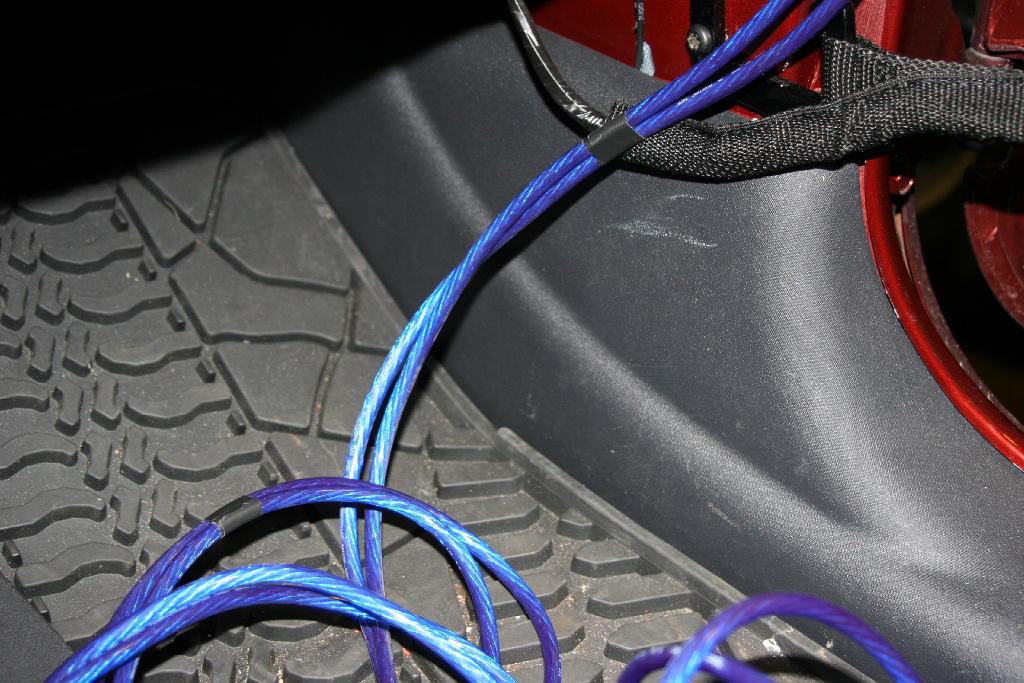
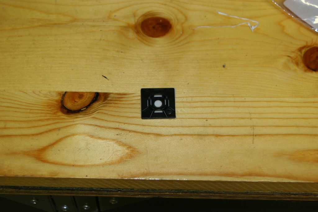
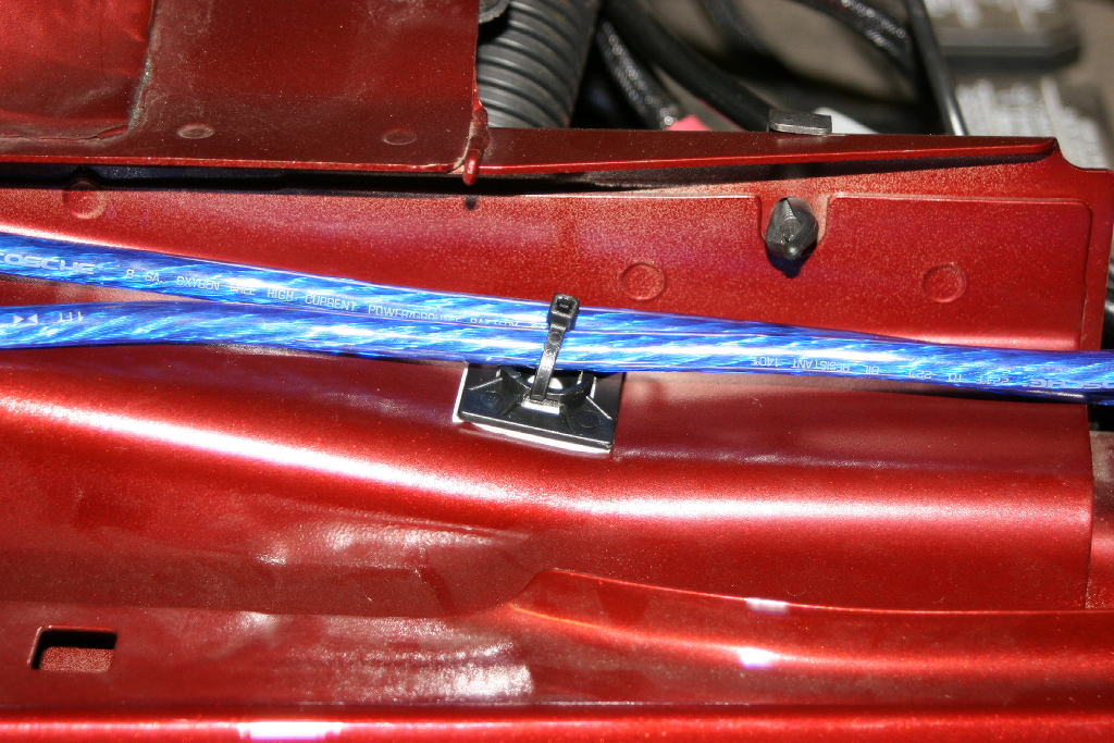
| Secure the wires along side the hood so that they don't get pinched. Use one of the zip tie bases. |
 |
 |
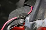
| Clean off the edge of the fender with alcohol, and attatch the base. Zip tie the wires in place. |
 |
 |
| |
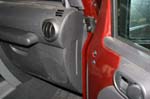
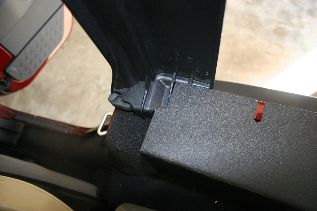
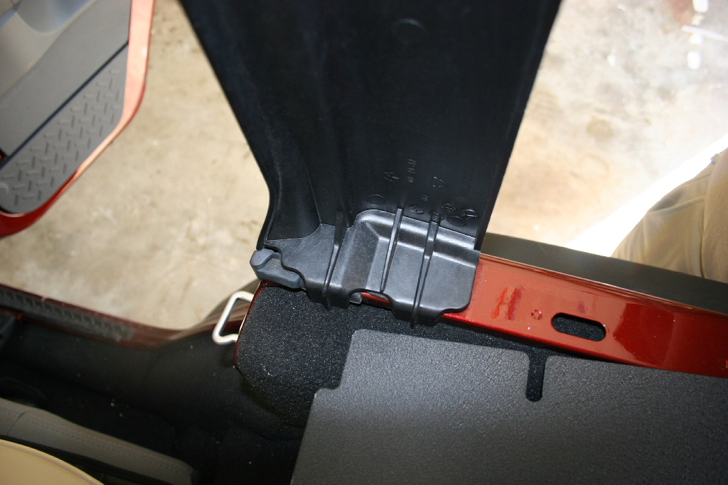
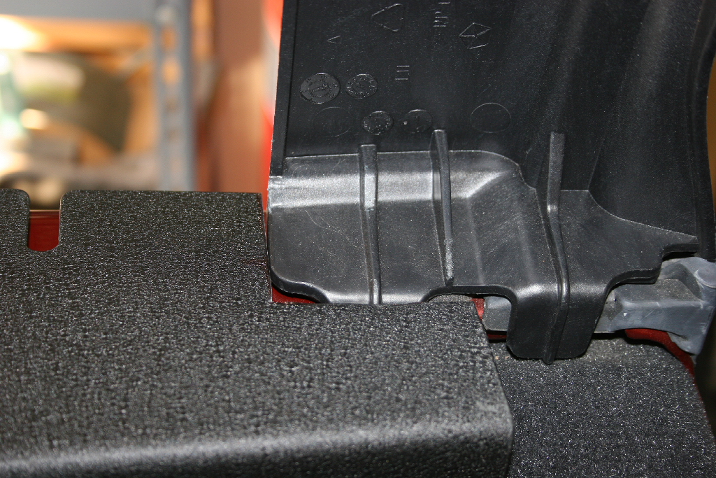
| Panel Installation: |
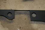
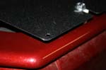
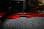
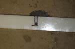
| I had a set of the original panels that were designed for the hard top. We quickly discovered that the soft top required a little modification to them. The follow on panels are being designed to have this cut and will be lower for the soft top. |
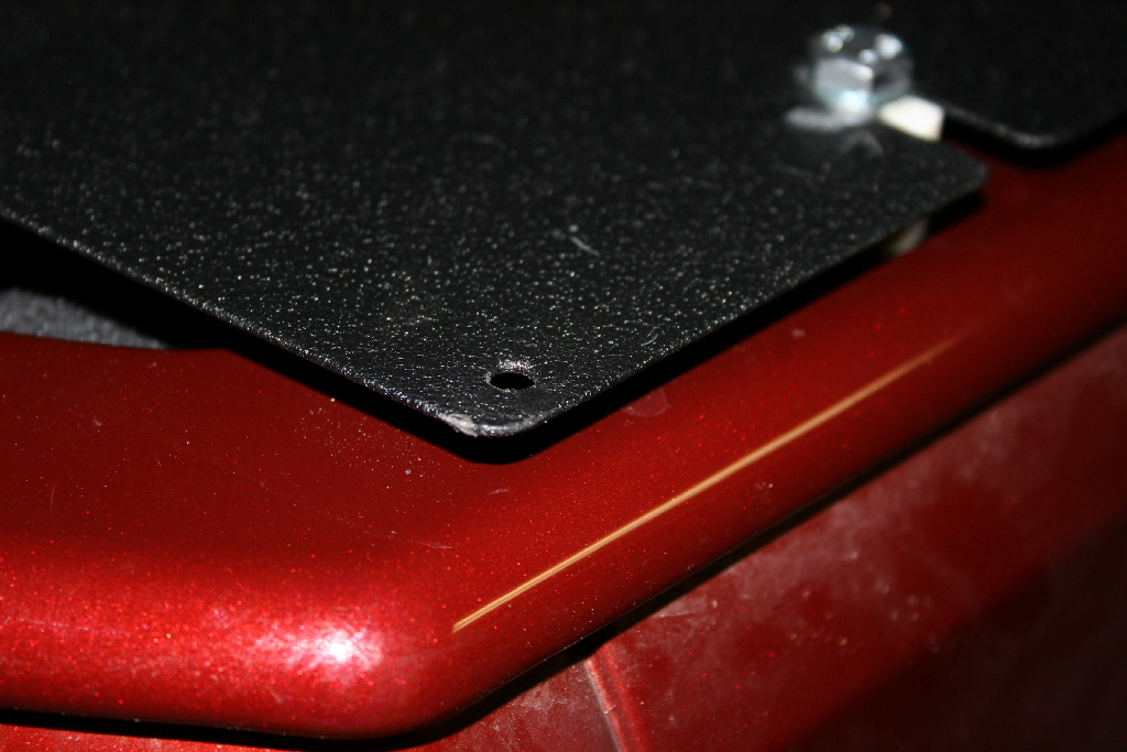
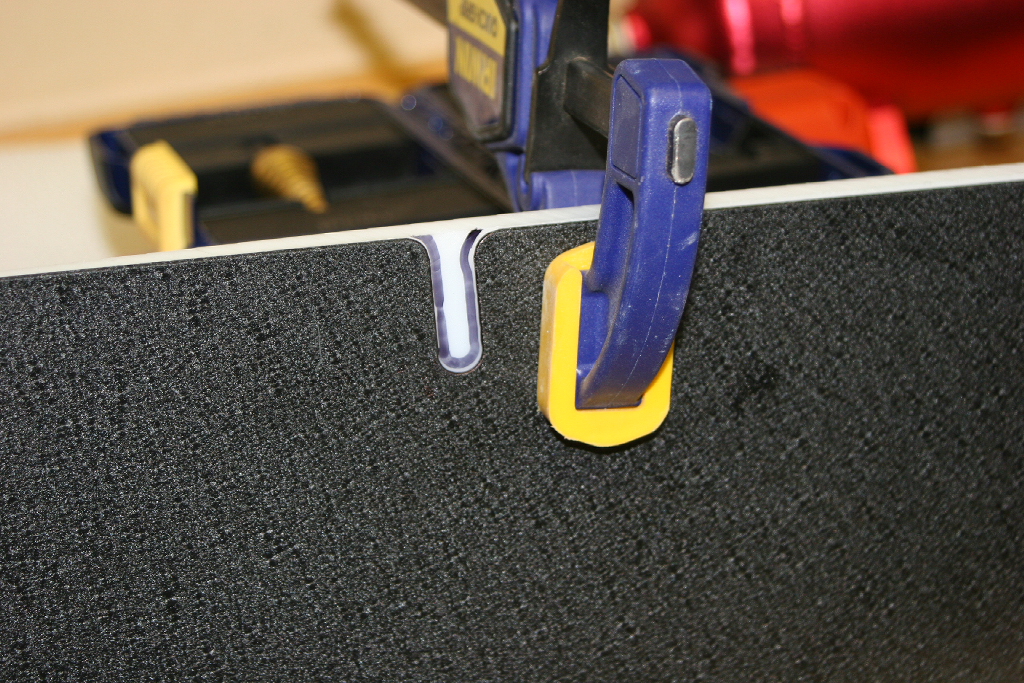
A small gap. |

Panel to surround issue |
Hard top cut not big enough. |
Opened the cut up to 2 3/8" sq. |
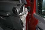
| Because I had the hard top panels I needed to trim of the back end of the panel where it rubbed on the soft top. |
 |
 |
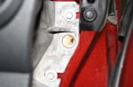
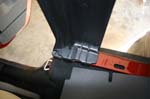
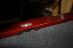
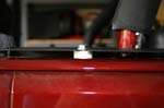
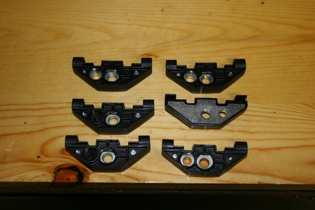
| I used to have the Hard top, but when I sold it I transferred the body nuts over to the new owner. So a quick stop by the dealership and I picked up a set of 6 for the hard top. These are not cheap nuts. $4-6 a piece. A set of nuts and bolts are being worked on for the soft top, so unless you really want the cool nuts there will be another option. |
 |
| Install the body nuts in the Jeep tub, they just clip in underneath. |
 |
 |
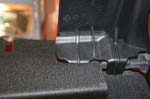
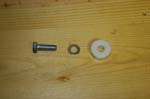
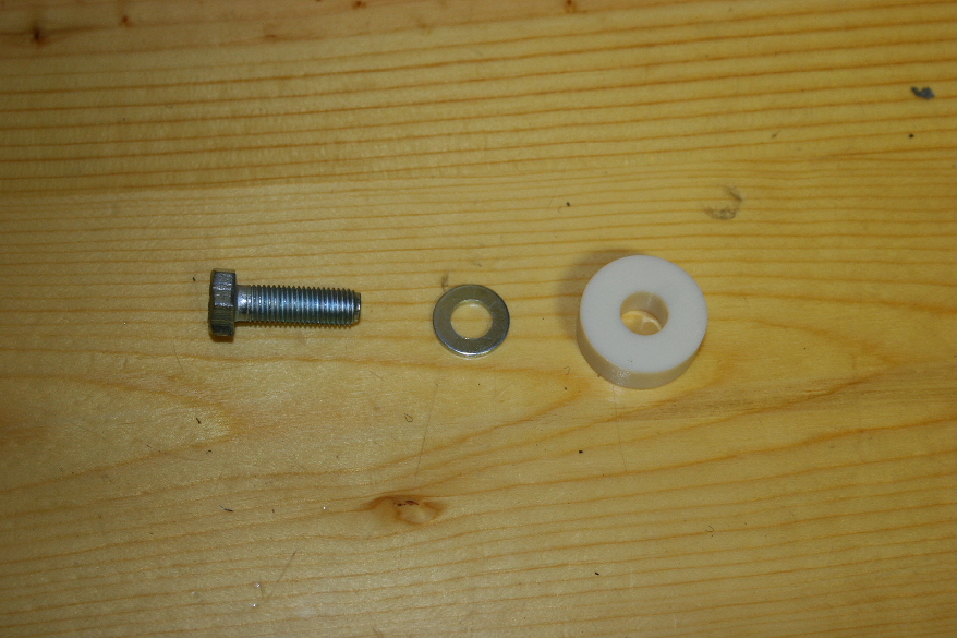
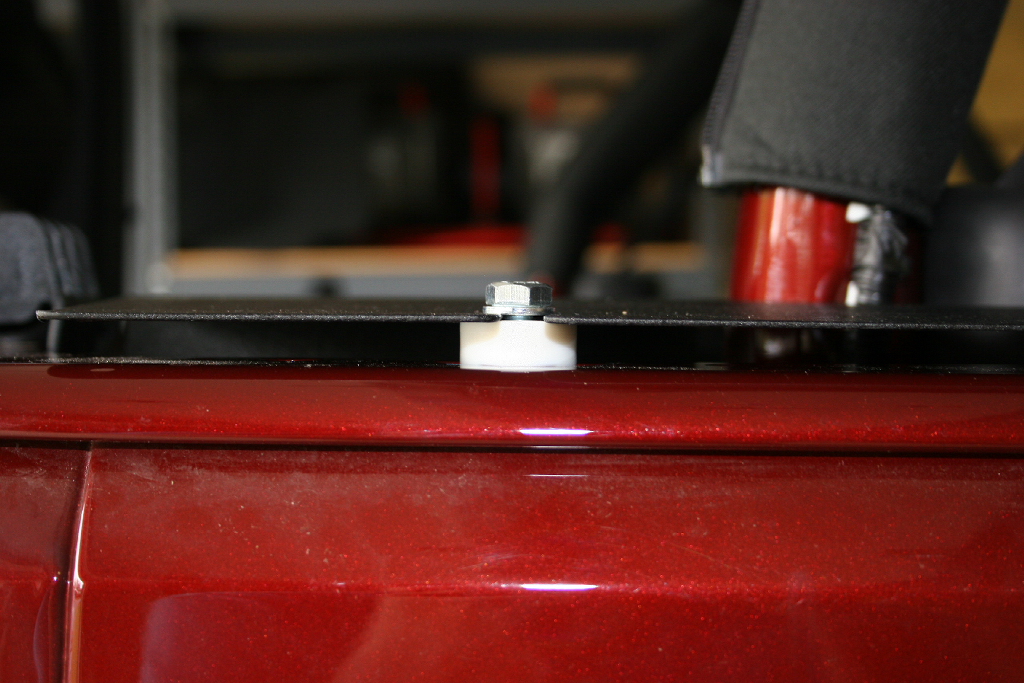
| I used a M8x1.00 25mm bolt, washer and a 3/8' plastic spacer to install the panels. Eventually a full length spacer will be installed between the body tub and the bottom of the power panel. The follow on panels for the soft top will shorter and will not need a spacer. |
 |
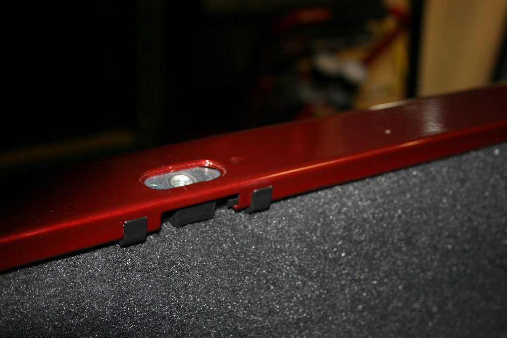
| Spacer installed. |
 |
 |
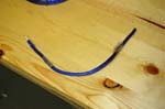
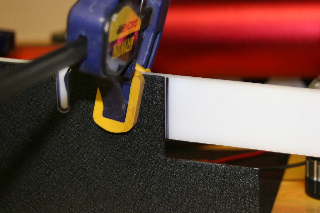
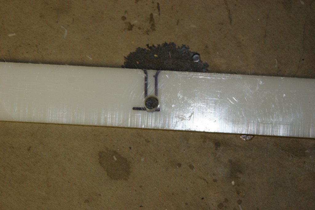
| 3/8"x1.5"x48" long plastic strips |
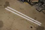 |
| Clamp and mark the strip for the holes and end. |
 |
 |
 |
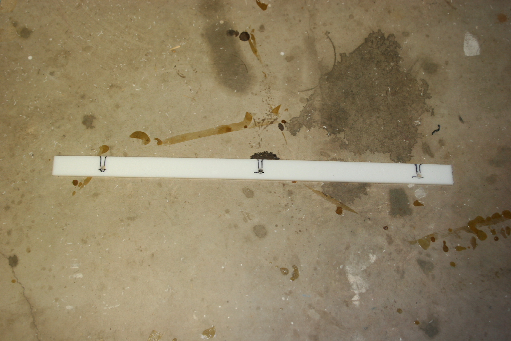
| Mark and drill a 3/8" hole. Cut off the excess end of the strip. |
 |
 |
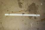
| Installed the full length spacer |
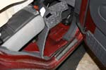
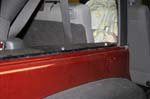 |
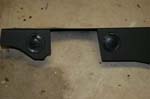
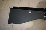
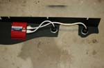
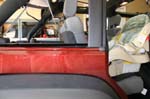
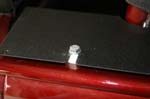
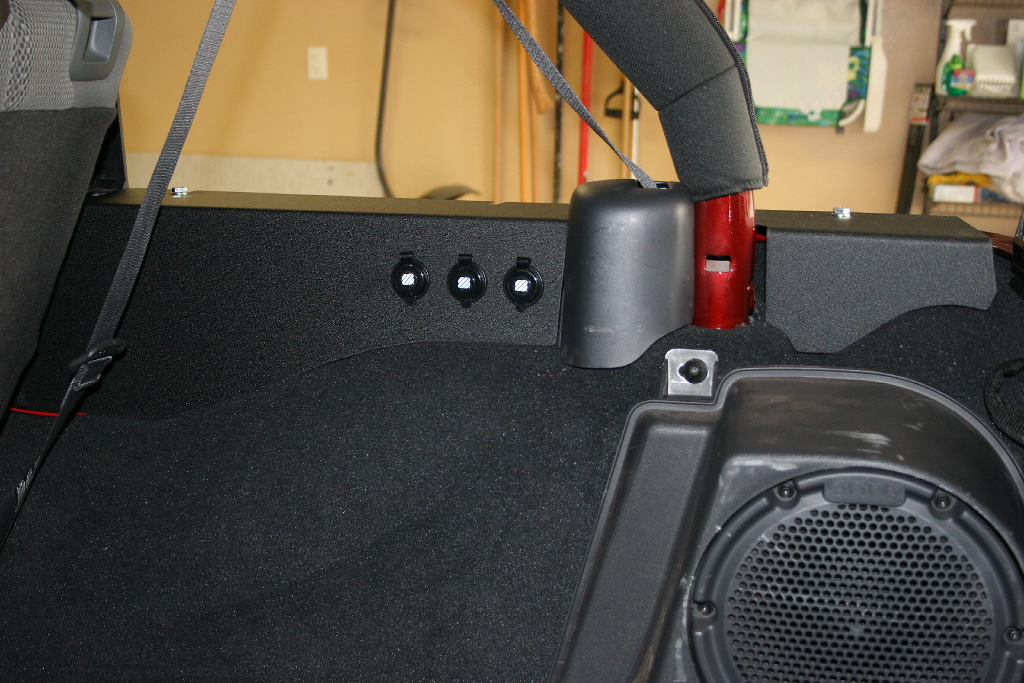
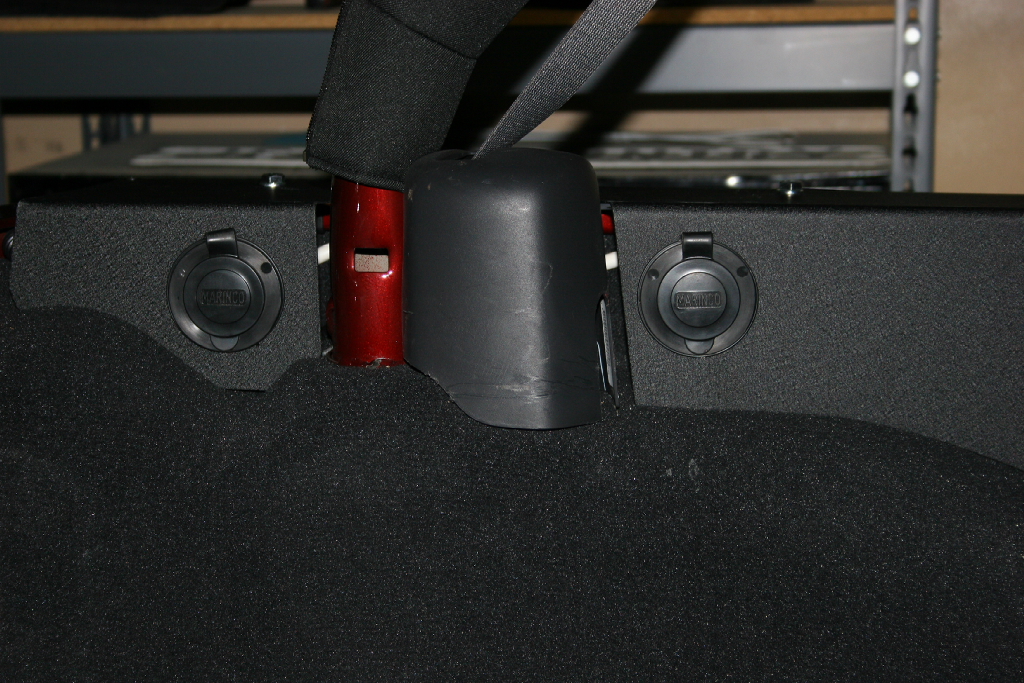
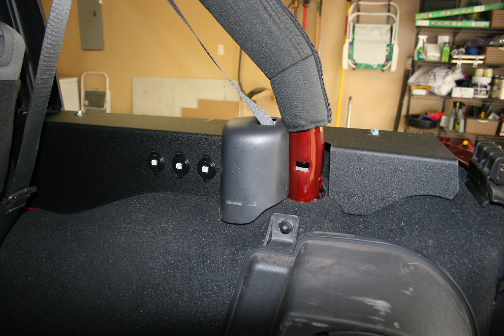
| Panels installed. |
 |
 |
 |
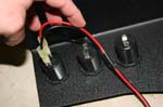
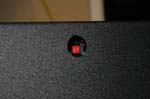
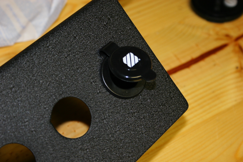
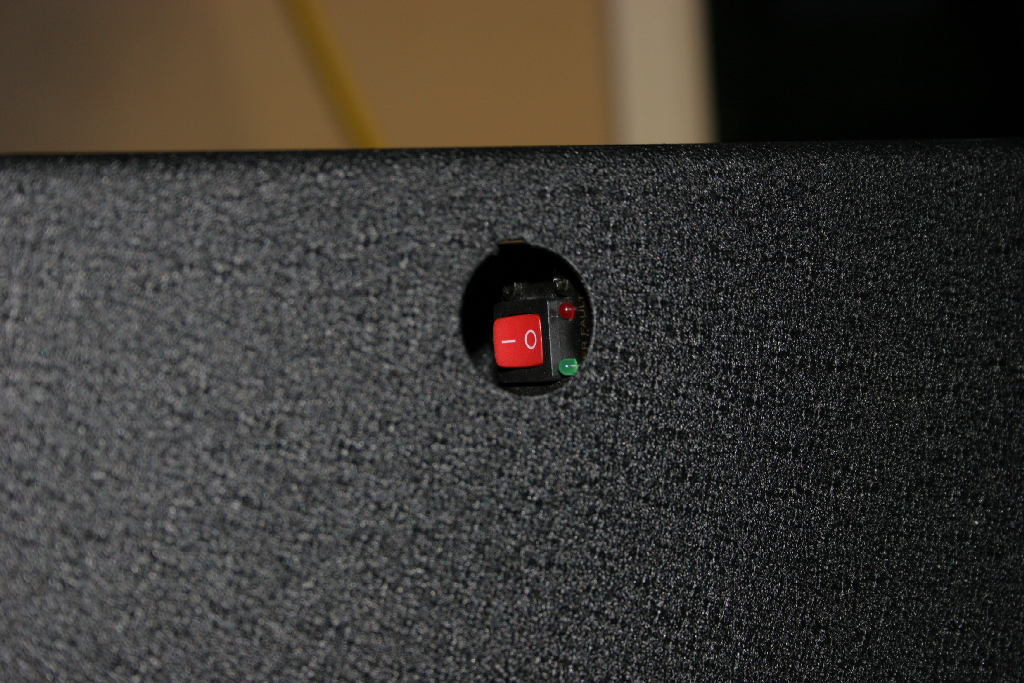
| You can reach in through the hole and turn on the power inverter. |
 |
| |
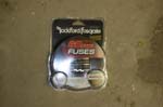
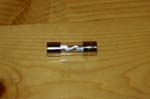
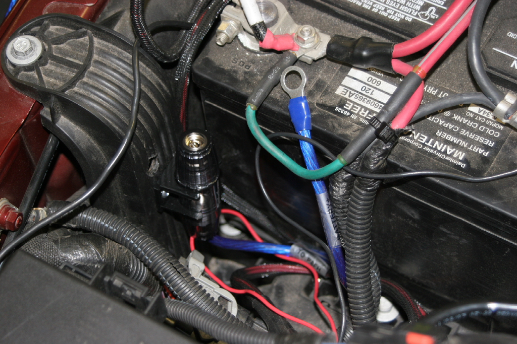
| Install the main fuse in the holder |
 |
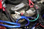
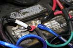
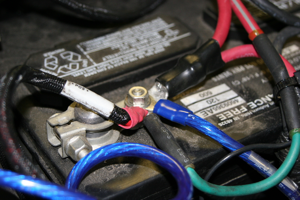
| Connect the positive and negative cables to the battery post. You will need a 10mm and 12mm combo wrench. |
 |
 |
| Test the power inverter by turning it on and plugging something into the 110vac outlets. You can test the 12vdc outlets. Just note that you have constant power supplied to these outlets and having something plugged in without the vehicle running will drain down your battery. |


