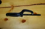
Kilby Enterprises has been pioneering onboard air systems for Jeep vehicles for some time now. They have finally released the air system for the new Jeep Wrangler JK's and for christmas my wife decided that since it was on my list of items that I wanted. Okay I really tried to get some new bumpers, but... I already had the Onboard Air system from Off Road Only installed and really wanted to see what the differences were between the two systems. I will make a few basic comments and leave it at that. ORO's system is easier to install, Kilby's is easier to maintenance. ORO's comes with everything that you need for an eventual AiROCK system, Kilby's doesn't. Both systems are about the same price, I think Kilby's was a little cheaper. I didn't buy the entire kit since I already had some Kilby stuff from my LJ and TJ projects and would need to adapt this one to AiROCK. You will be able to use either the 1.75gallon or 2.75 gallon Kilby Tanks with this system.
| Installation: |
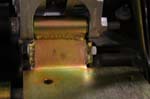
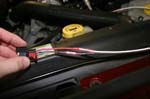
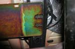
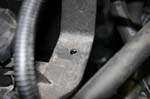
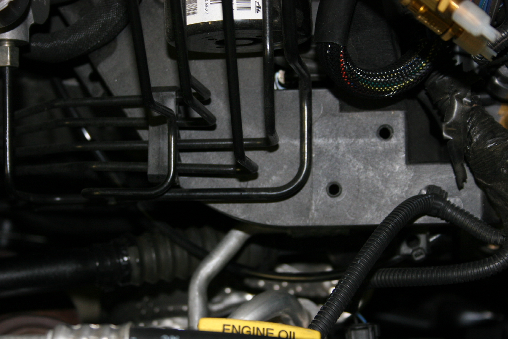
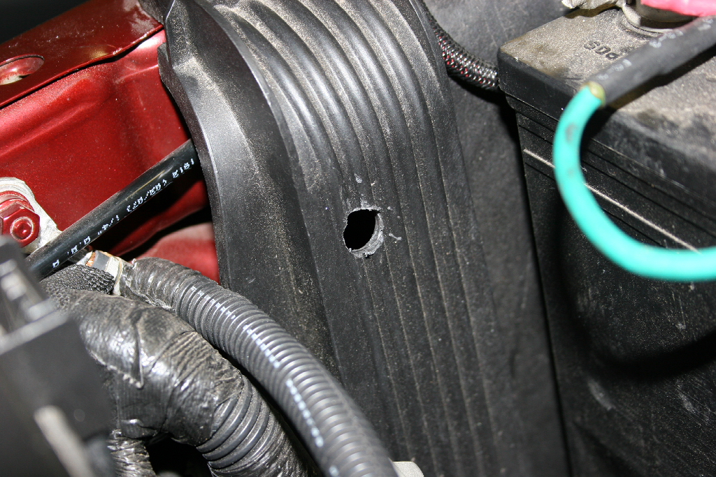
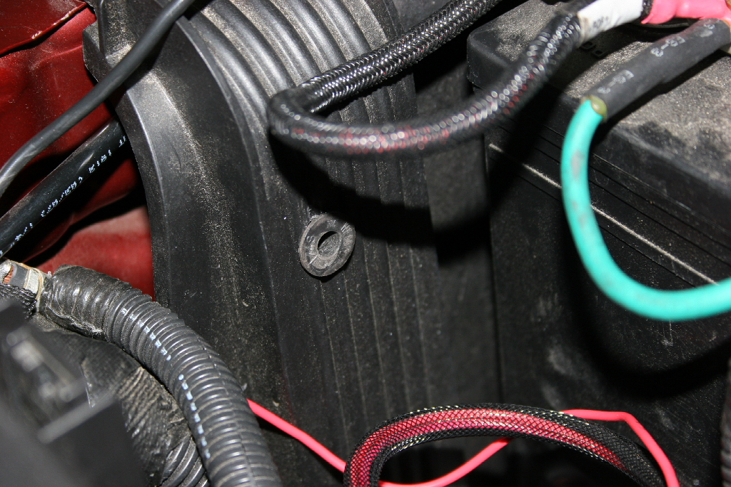
1. Cut the plastic near the ABS module using picture as a guide. You will need about 1" minimum. Cut slowly, you are cutting around wires and brake lines with a hacksaw. |
 |
 |
 |
| |
|
|
|
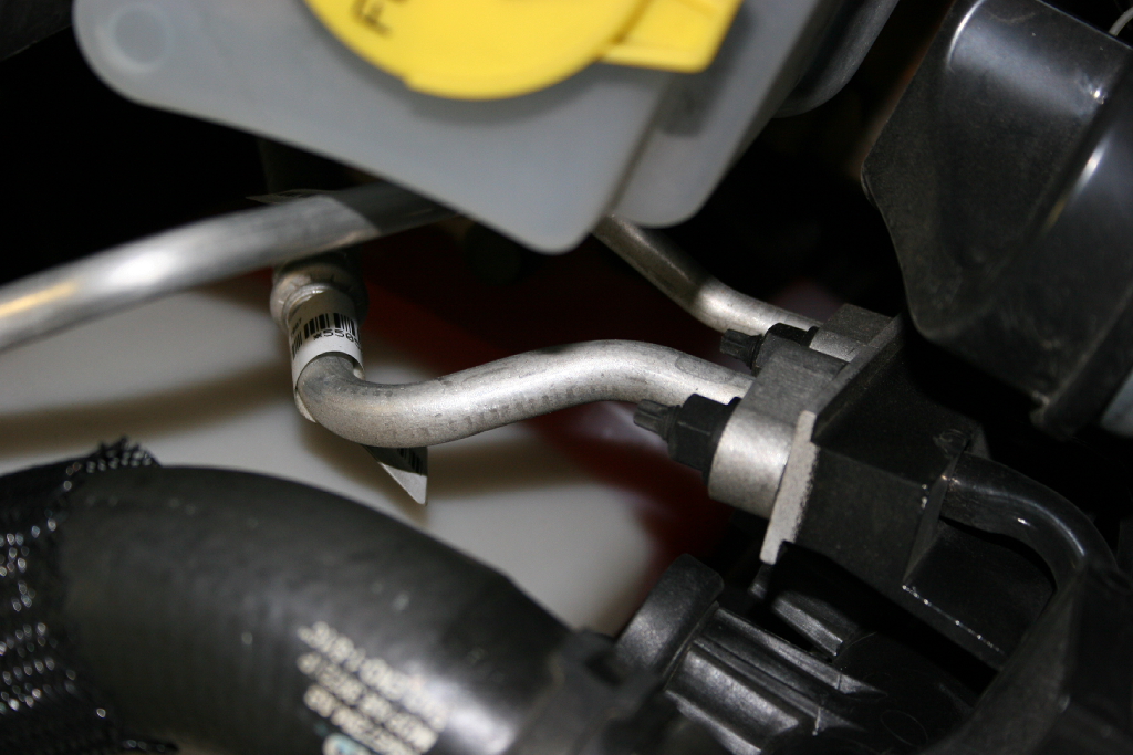
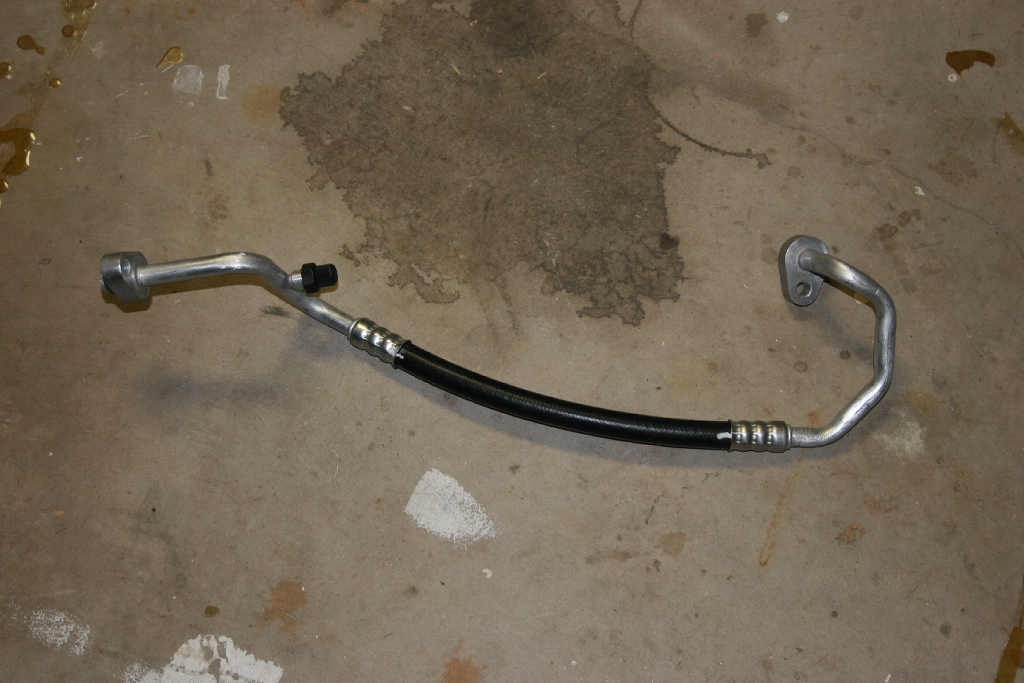
2. Take vehicle to certified A/C shop & have supplied A/C line swapped. This will take about an hour if done right. They will vacuum down the system, change out the line, vacuum the lines again, leak check, and then refill the system. My factory system had a leak on it and I had lost most of my coolant already. The leak was in the line we replaced.
|
 |
 |
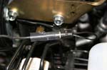
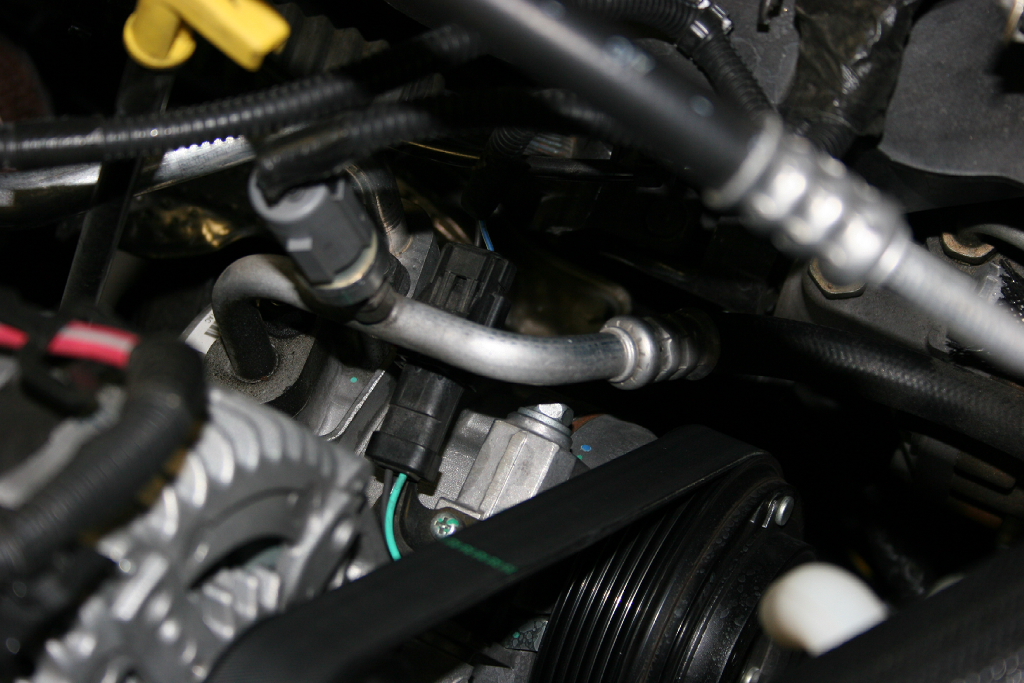
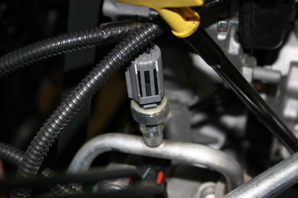
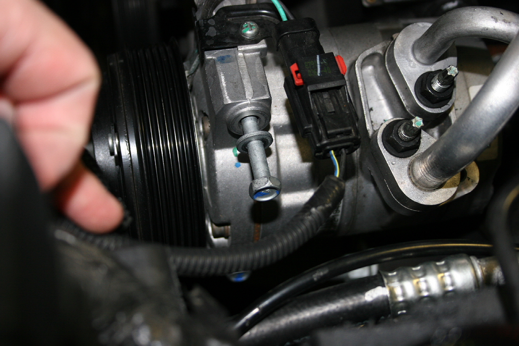
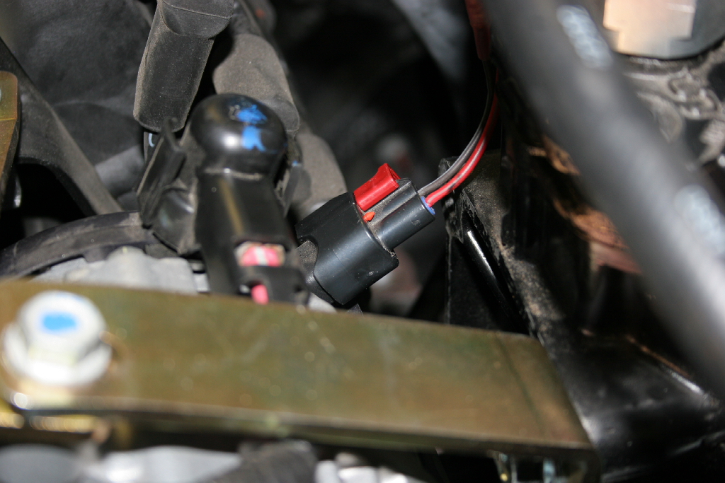
3. This sensor unplugs and then unscrews. It can be on fairly tight, but the A/C shop can get it off. |
 |
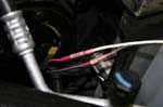
| Note: how the line goes behind the other one from the compressor. |
 |
 |
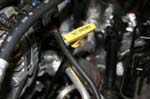
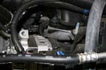
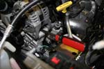
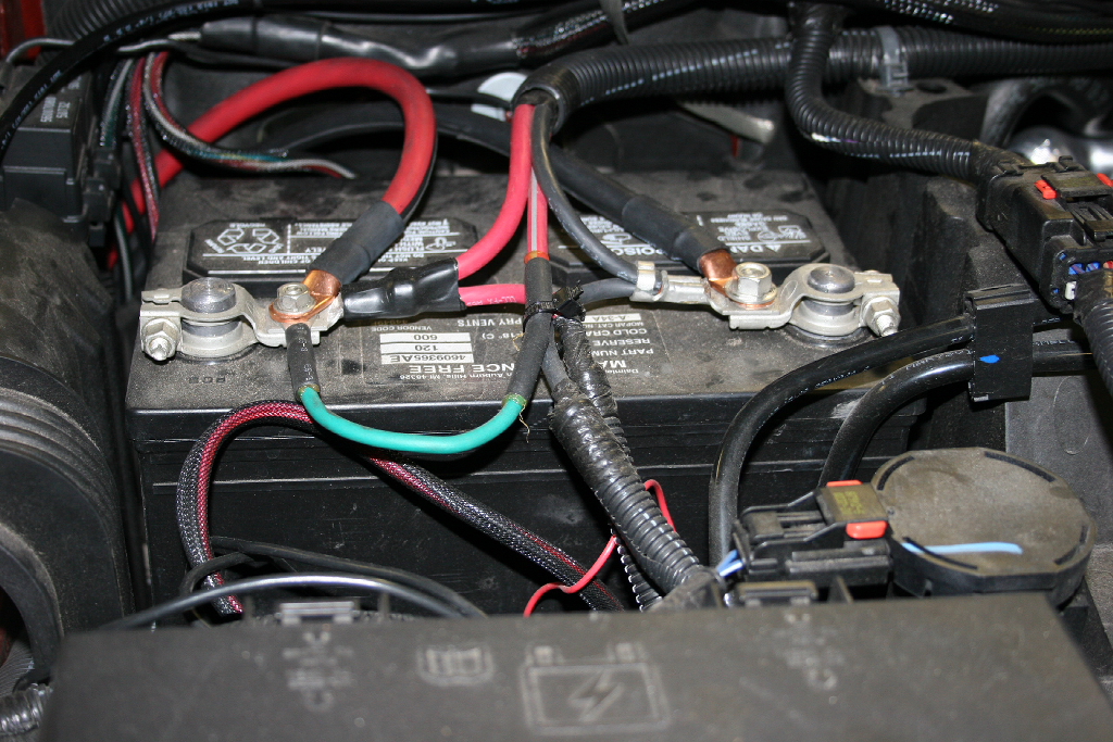
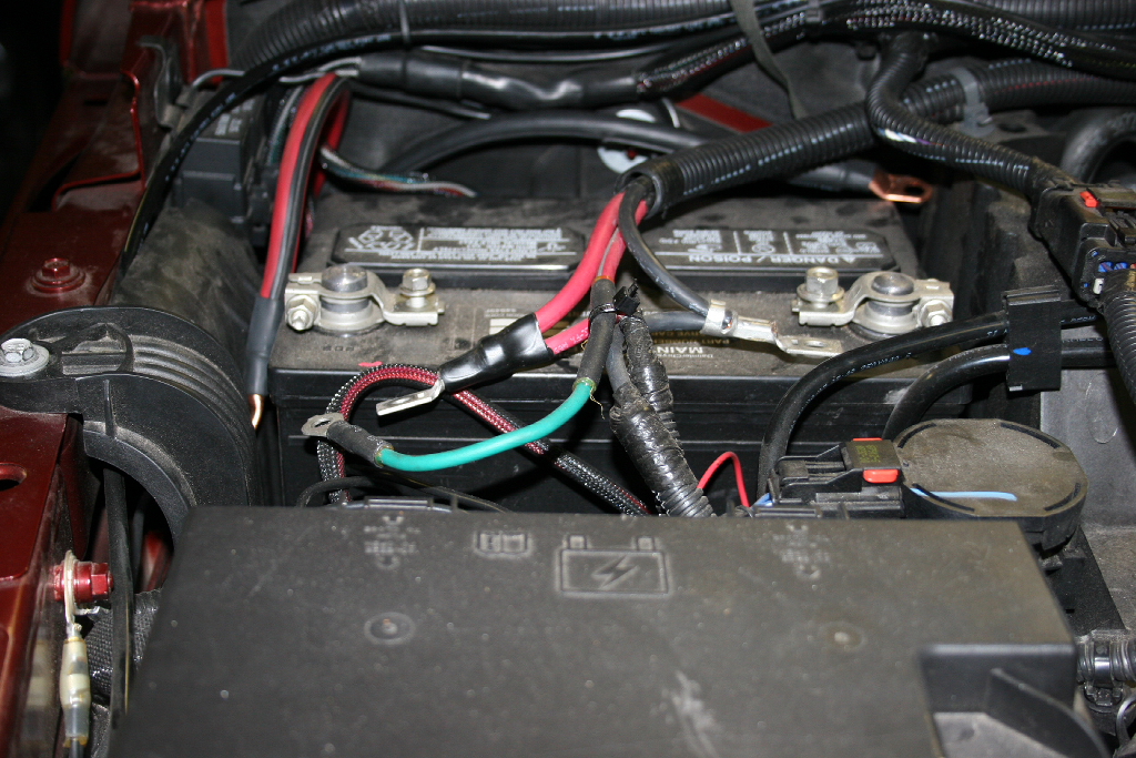
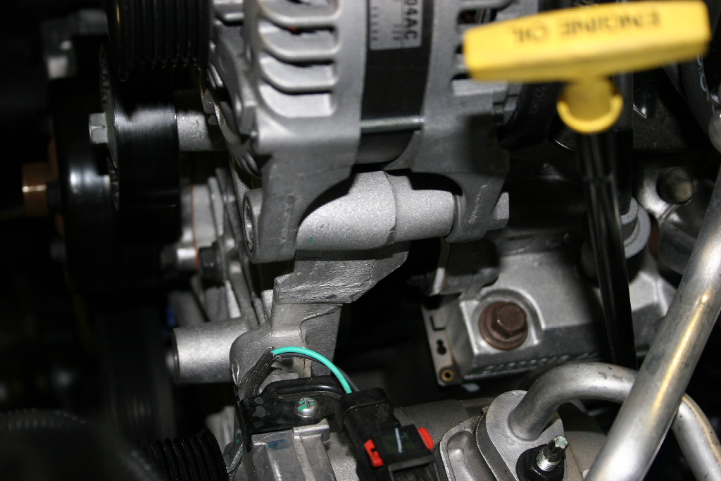
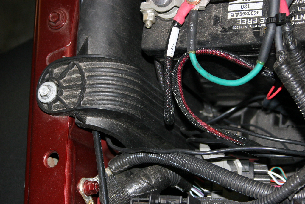
| 4. Disconnect positive and negative battery terminals. I will recommend doing both since from experience working with the alternator can suddenly give you an unexpected shocks. You will need a 10mm and 12mm combo wrench |
 |
 |
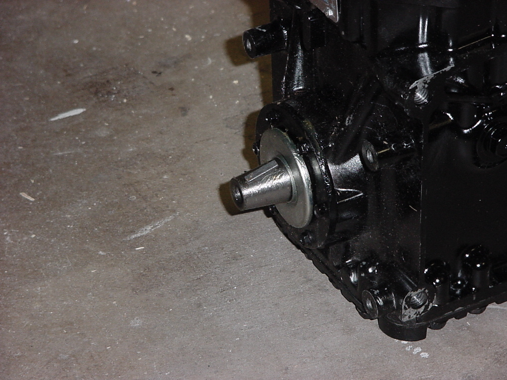
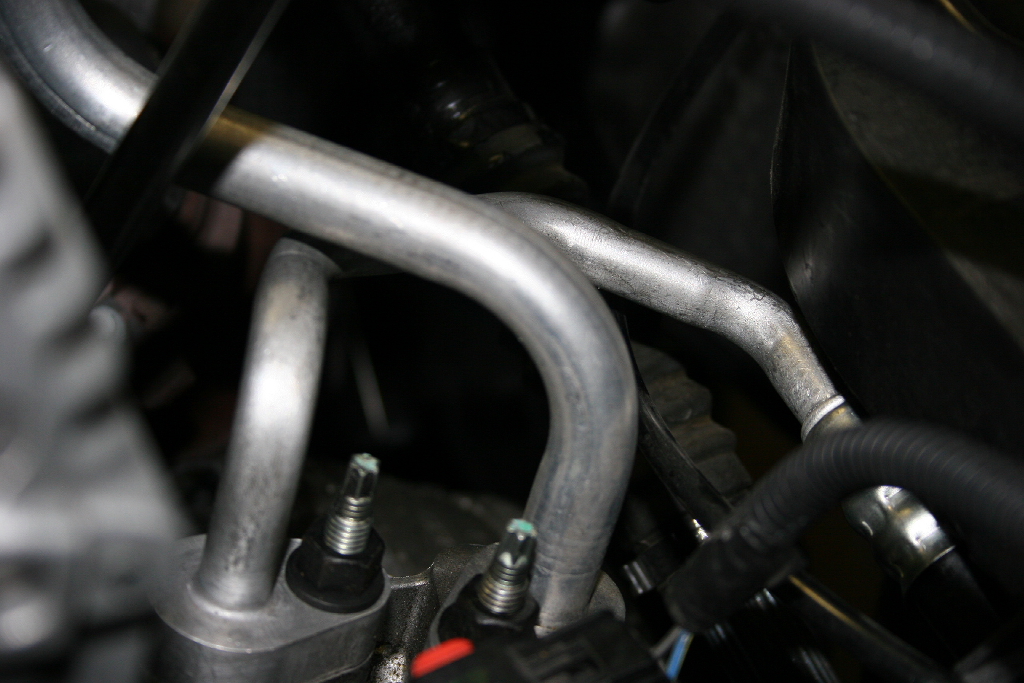
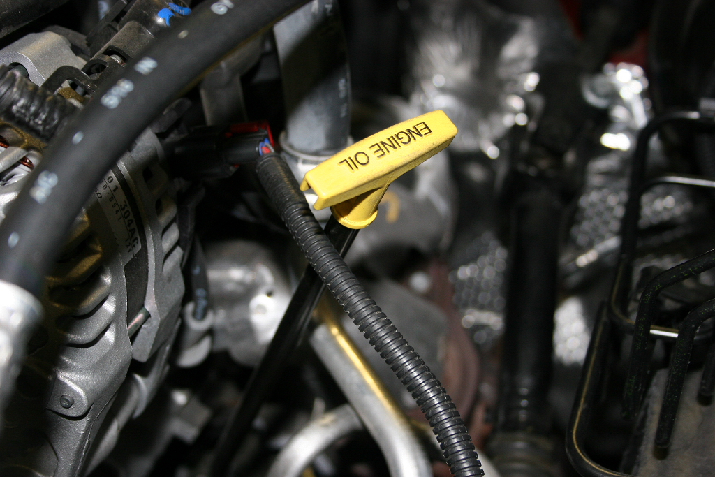
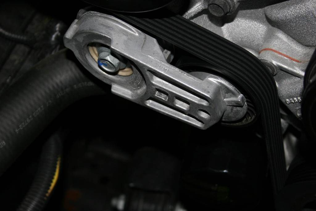
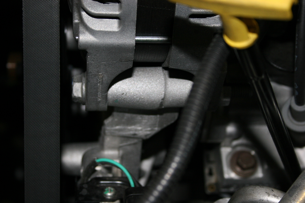
5. Bend oil dipstick tube back and towards the engine for clearance. It will sit almost against the heat shroud for the exhaust. You will adjust this position after you get the compressor in. It sits behind the compressor. |
 |
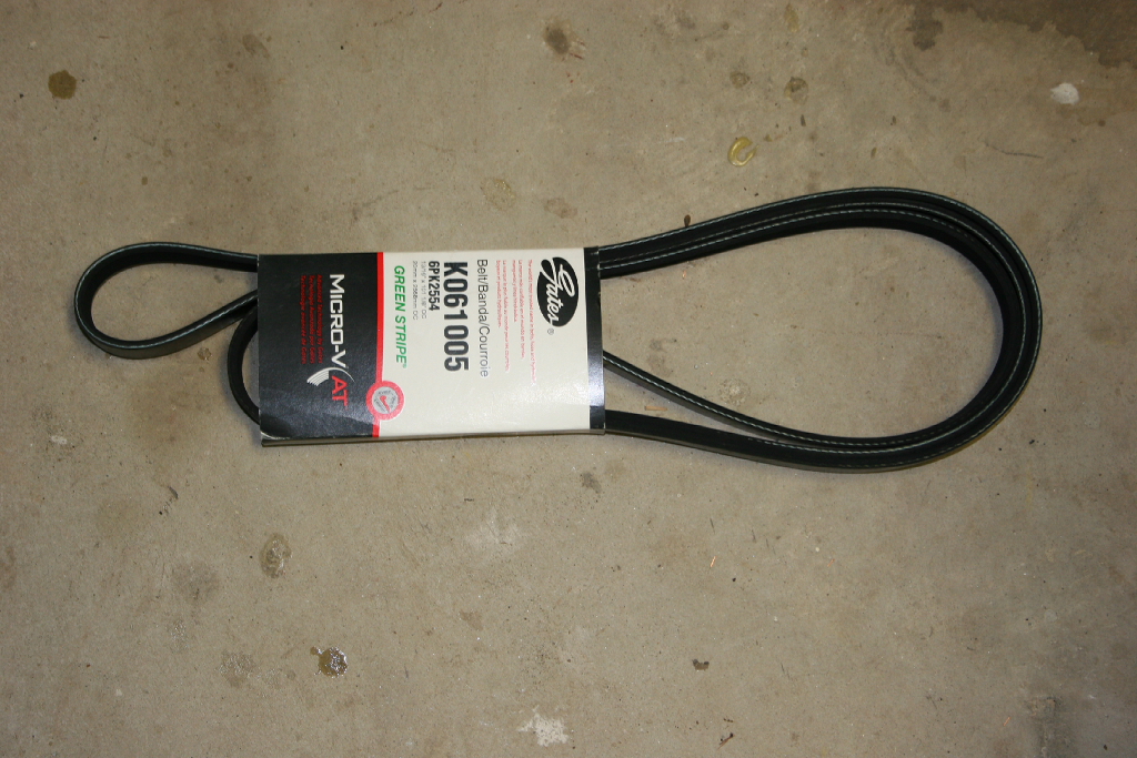
6. Remove serpentine belt, but inserting a 3/8" ratchet, or breaker bar into the belt tensioner and push down. |
 |
 |
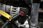
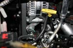
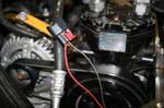
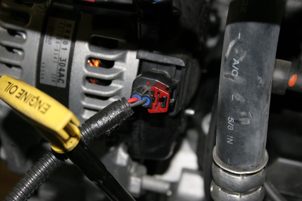
7. Unplug the alternator control lead. You will need to pull the red tap up before it will unclip. Remove the wiring from the upper alternator support bracket. |
 |
 |
| 8. Remove the wire hold down. |
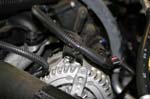 |
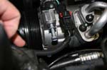
| 9. Remove the intake nut and the alternator bolt with a 13mm socket. |
 |
 |
| 10. Remove the intake to alternator bracket. |
 |
11. Remove drivers side alternator bolt with a 16mm socket.
|
 |
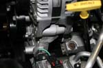 |
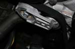
| 12. Loosen the alternator piviot bolt with a 16mm socket. |
 |
| Note: You may need to gently pry the alternator up to get it free of it's mount. |
 |
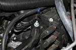
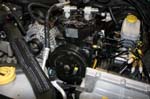
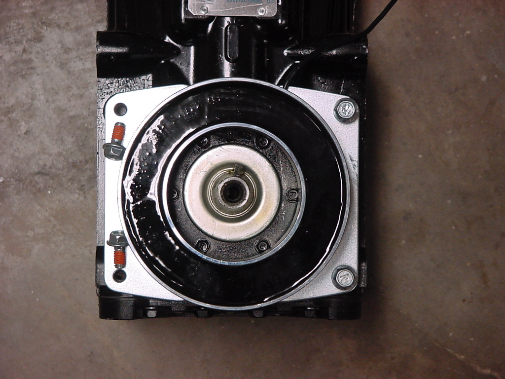
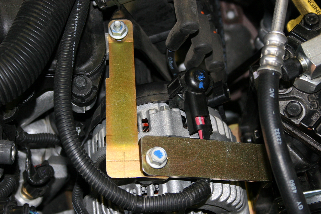
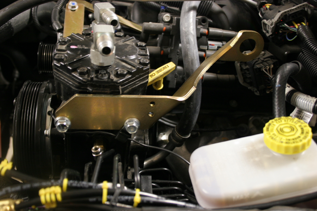
| 13. Remove the upper front A/C compressor bolt with a 13mm socket. |
 |
 |
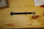
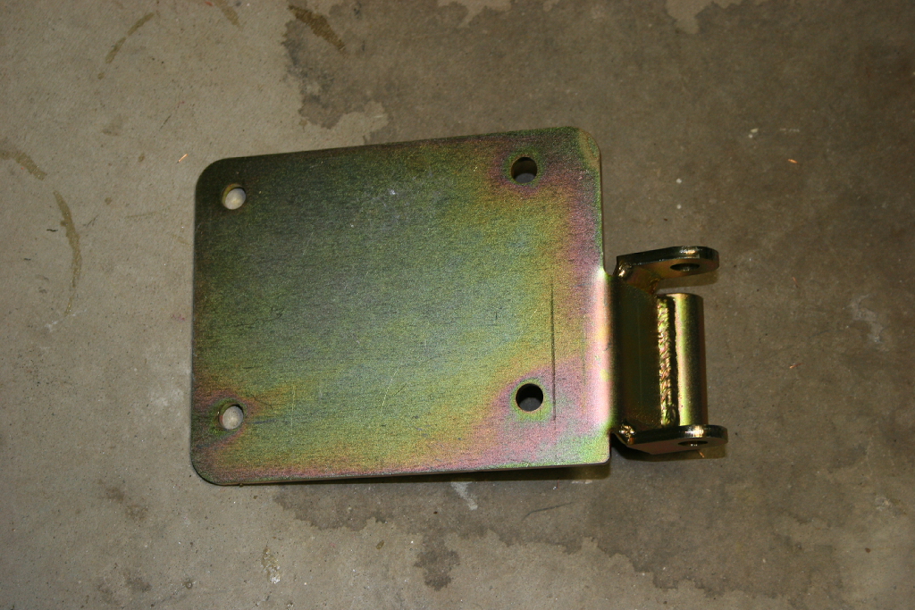
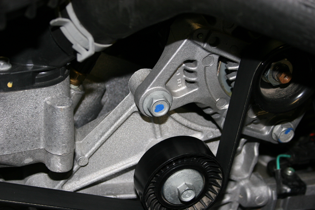
14. Install compressor mounting bracket using the provided M10x110mm bolt, (2) 3/8" washers and M10 nut. The bolt will go through the compressor bracket and the factory alternator mount. |
 |
 |
| 15. Use factory alternator mounting bolt to reattach alternator to air compressor mounting plate. Don’t tighten any bolts yet. |
 |
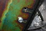
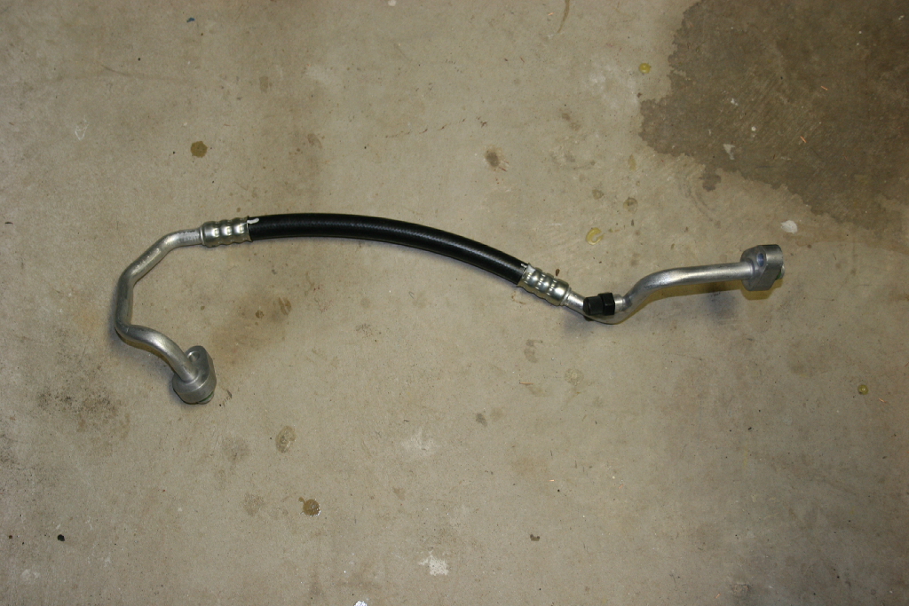
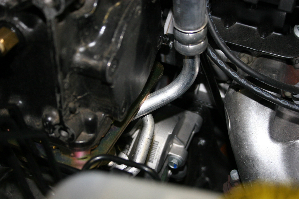
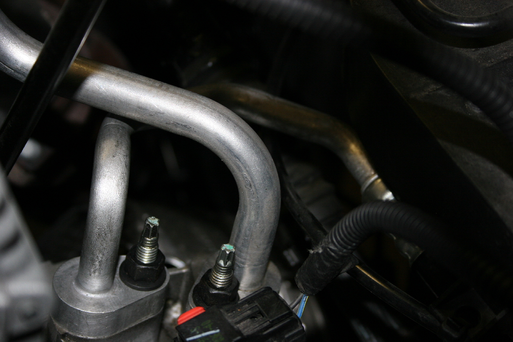
| 16. Now check for clearances underneath the compressor plate. The suction line (big A/C line) will probably be hitting the bottom of the plate. You may need to bend this down and away from the engine. It's aluminum and bends fairly easy, just take your time and do it a little at a time. The compressor plate should sit down against the lower compressor mounting brace. |
 |
17. Tighten M10x110mm bolt. Then tighten the factory alternator mount bolt. Tighten the Alternator piviot bolt. |
|
|
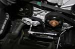
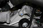
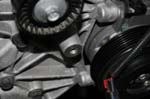
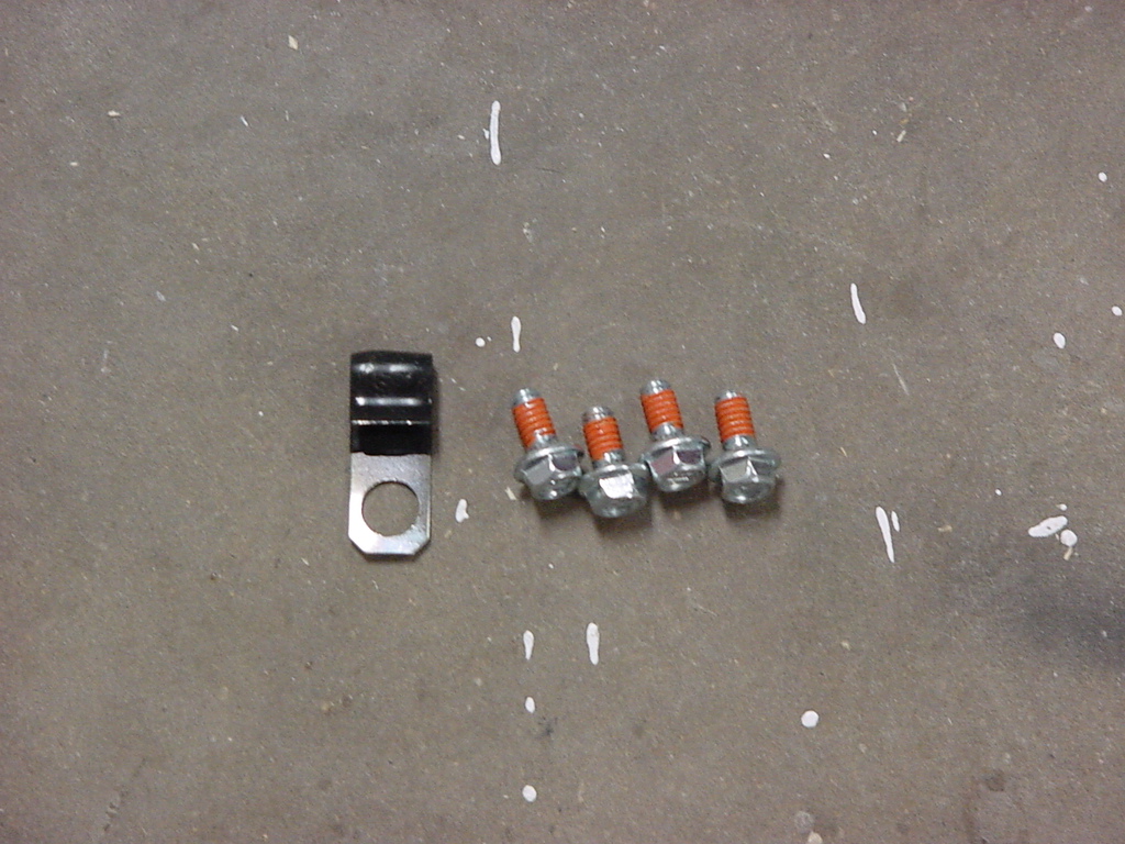
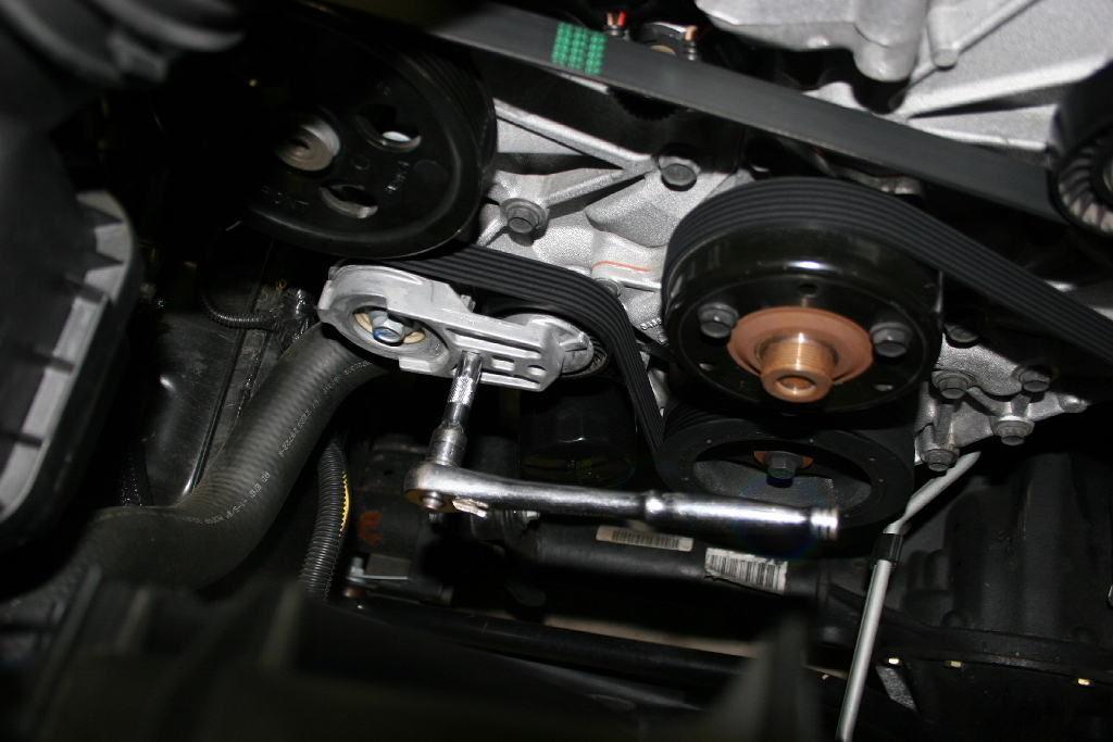
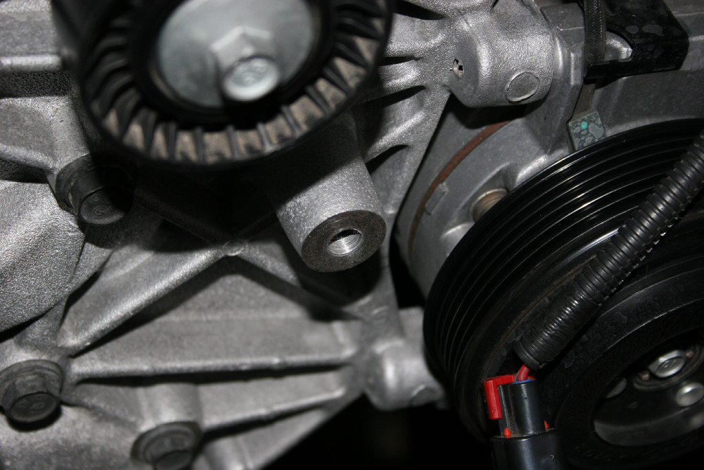
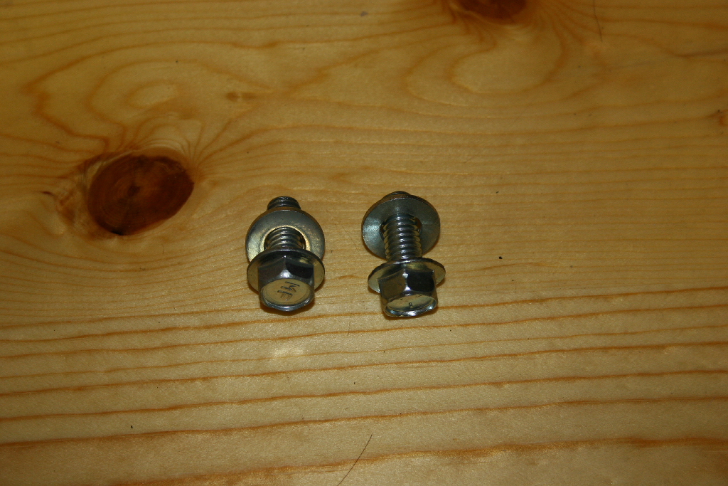
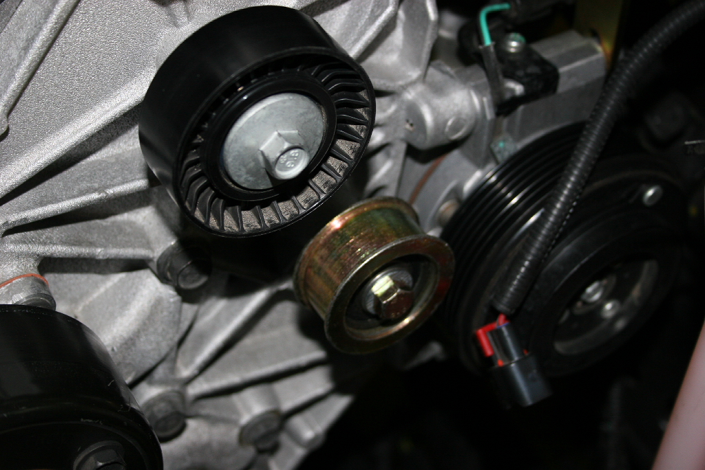
18. Install supplied idler pulley and bushing using M10x35mm bolt & two 3/8“ washers (thicker washer behind pulley). This goes on the threaded boss on the front of the engine below the factory idler pulley. You will need a 14mm socket.
Note: Mine squealed and I needed to adjust the position of the pulley slightly. I swapped the washers around.
|
 |
 |
 |
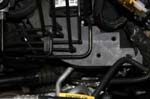
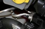
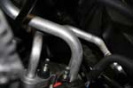
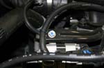
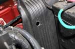
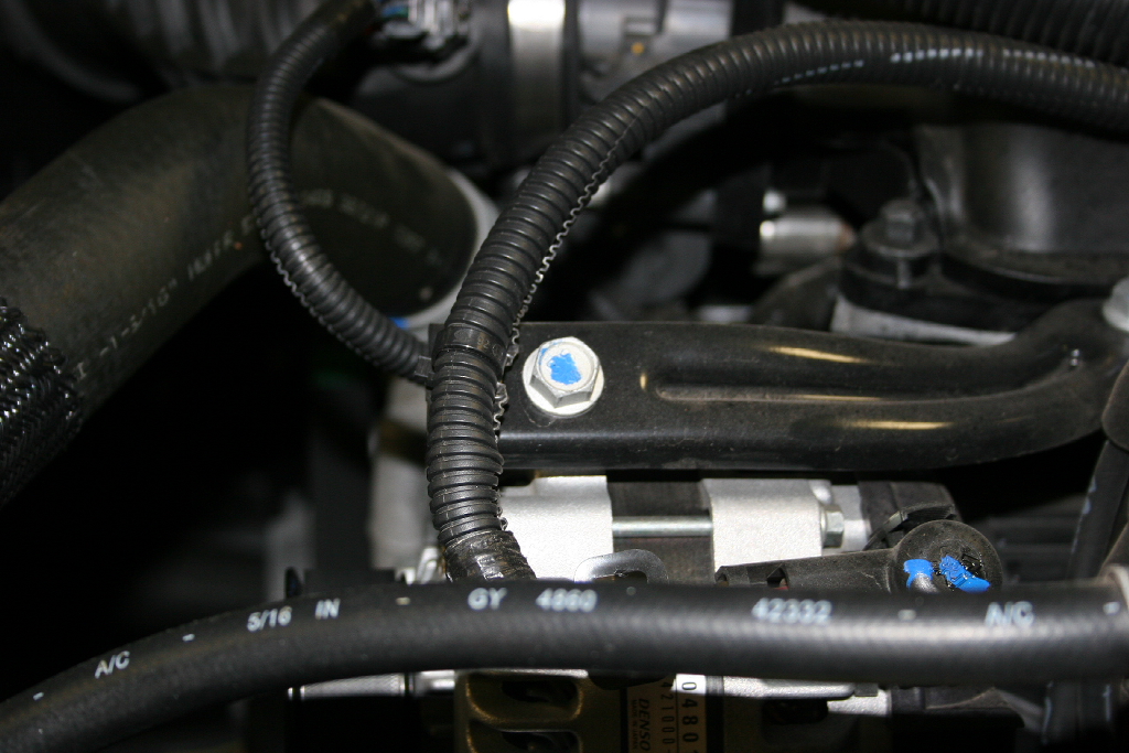
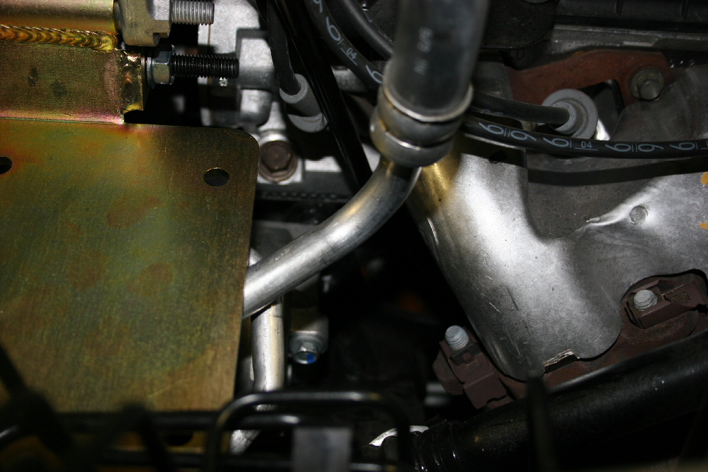
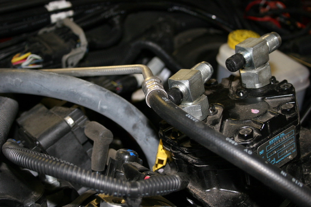
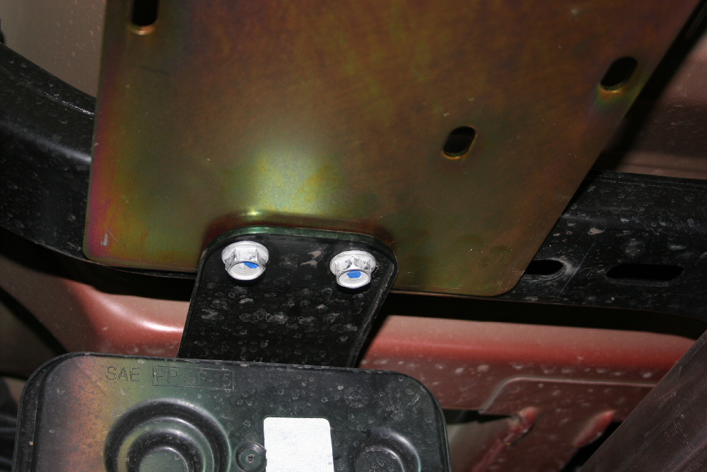
19. Place compressor on mounting plate & check for clearance to the A/C line & ABS lines. You will need to bend these back to gain clearance. The ABS lines are the hardest to bend, just take it slow. |
 |
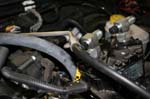
A/C Line
|
A/C Line
|
A/C Line
|
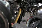
ABS Line
|
ABS Line
|
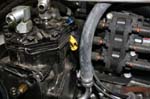
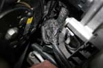
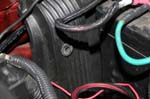
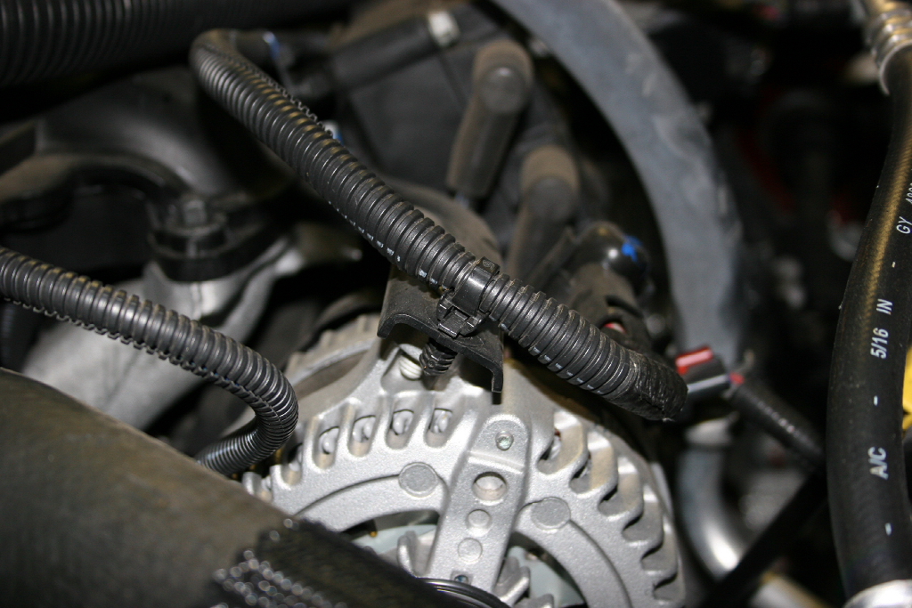
| 20. You will need to cut some of the wire wrap off this cable bundle and tuck everything back with a zip tie or two. This is really close to the pulley and belt. |
 |
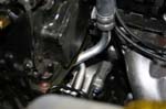
| 21. Loosely install the compressor to alternator bracket using a 3/8" x 7/8" Bolt and 3/8" washer. You will have a hard time getting the bolt in after you install the compressor. |
 |
 |
| 22. Ensure that the alternator wire is between the alternator and the bracket. |
 |
| 23. Install the lower compressor mounting brace using the upper A/C compressor mounting bolt that was just removed. Do not tighten this bolt down, just leave it really loose. Compressor bracket removed for clarity. |
 |
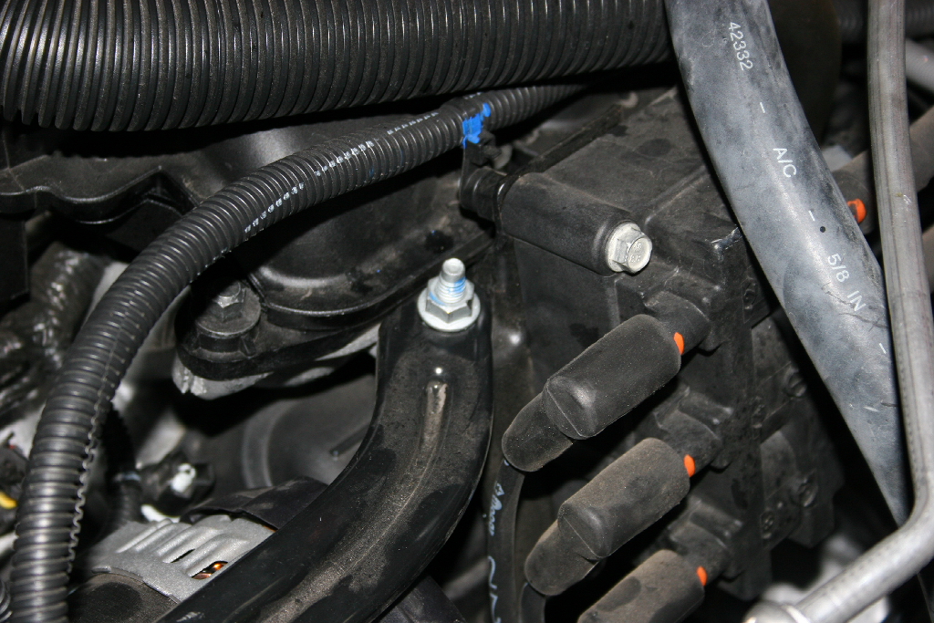
| 24. Bolt the compressor to the compressor bracket with (3) 3/8"x1.25" and (1) 3/8“ x 1.5” bolts and (4) 3/8" washers. The 1.5" bolt will go through the lower compressor mounting brace and air compressor bracket. Start with the rear inside bolt. This bolt is hard to install because of the A/C lines. So get it in and snug before you move on to the other bolts. These lines will have to be bent slightly for clearance. |
 |
|
| 25. Tighten the A/C compressor bolt with a 13mm socket. |
|
| 26. Tighten the (4) Air Compressor bolts with a 9/16" combo wrench. |
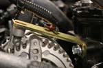
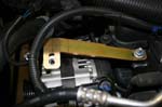
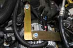
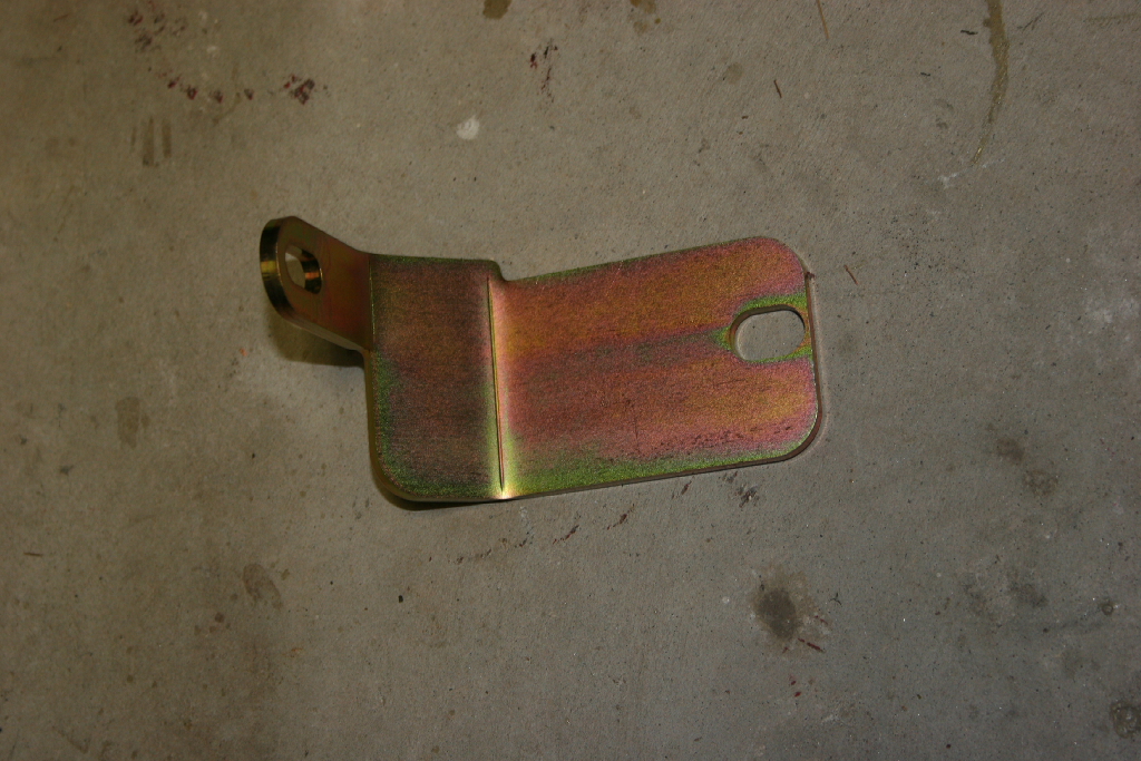
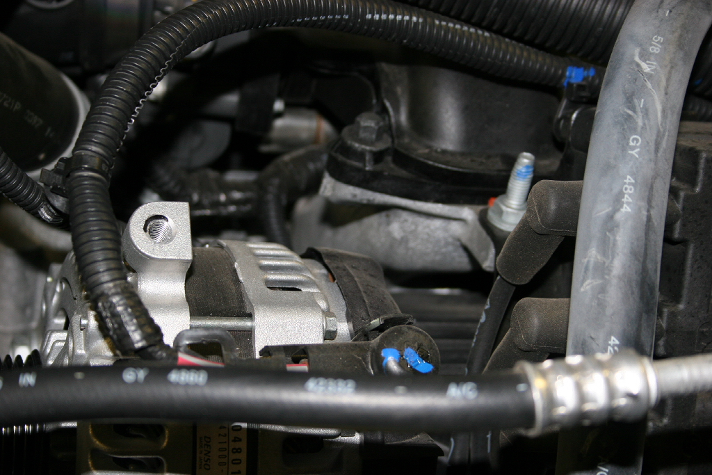
27. Install the supplied alternator brace to intake with the factory hardware. The compressor to alternator brace will go on top of this brace. You will use a washer under the nut and bolt. |
 |
 |
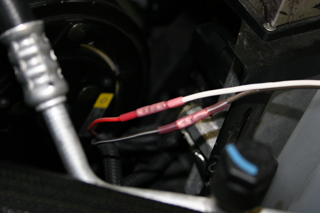
28. Splice alternator wires to extend. If you are using butt connectors, they make an underhood connector that has heatshrink tubing already. You will need to offset the cuts by about 1" to allow for the thicker diameter of the butt connector. Length of wire will depend on how far you need to route it. |
 |
 |
 |
 |
 |
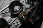
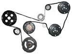
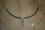
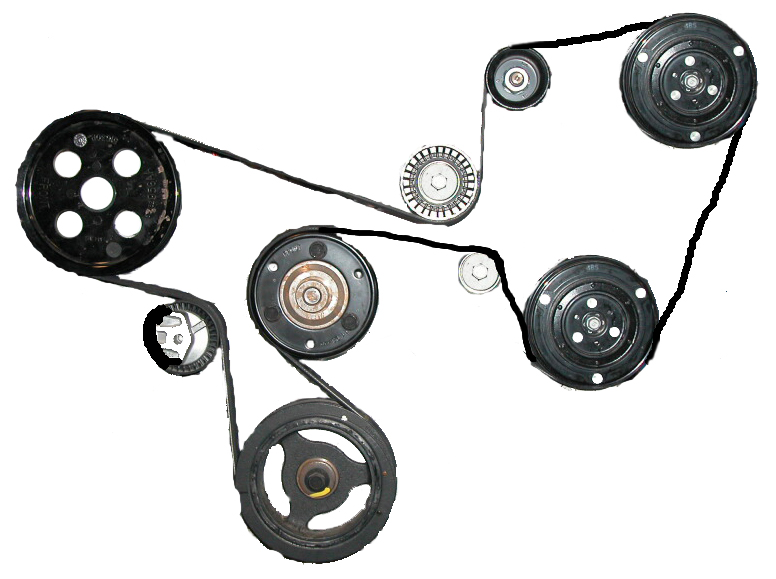
29. Install supplied serpentine belt. Here is the routing diagram. |
 |
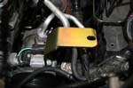
| 30. Install the coalescer filter bracket to the side of the compressor using (2) 3/8"x7/8" bolts and (2) 3/8" washers. |
 |
 |
| 31. Double check all bolts and nuts. |
| |
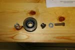
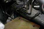
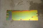
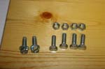
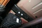
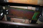
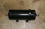
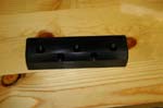
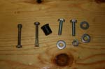
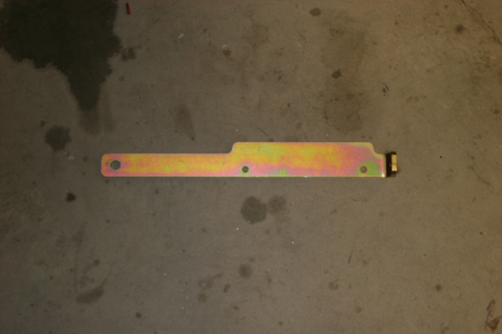
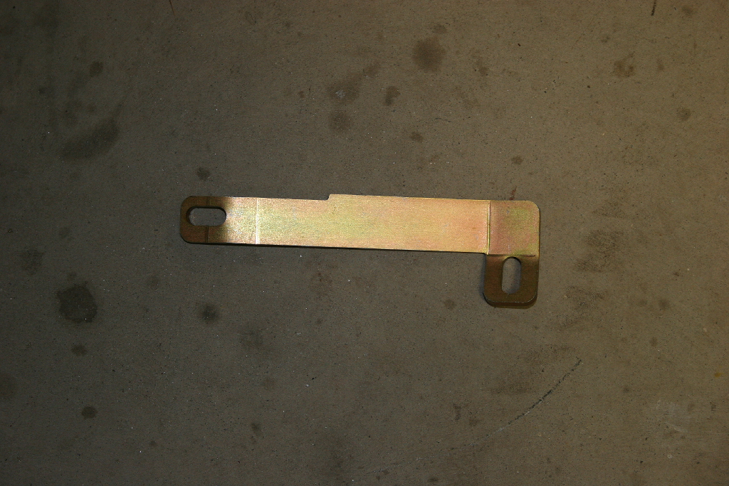
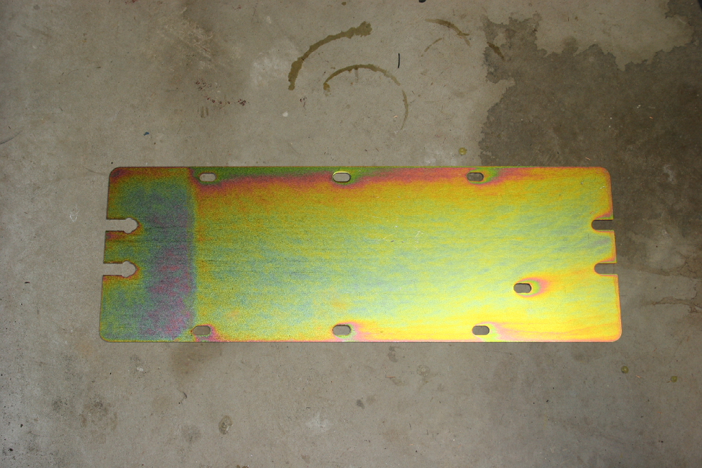
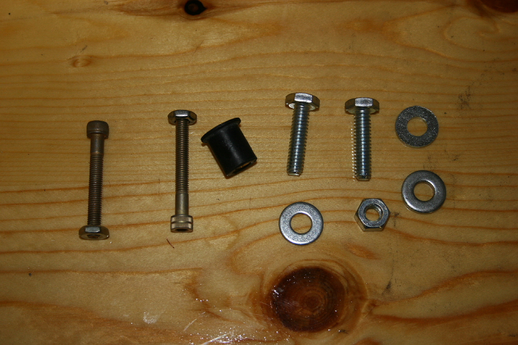
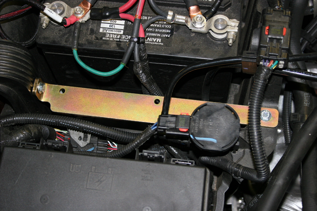
| Air Tank Mounting Plate Installation: |
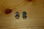
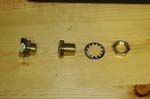
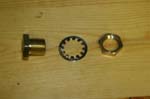
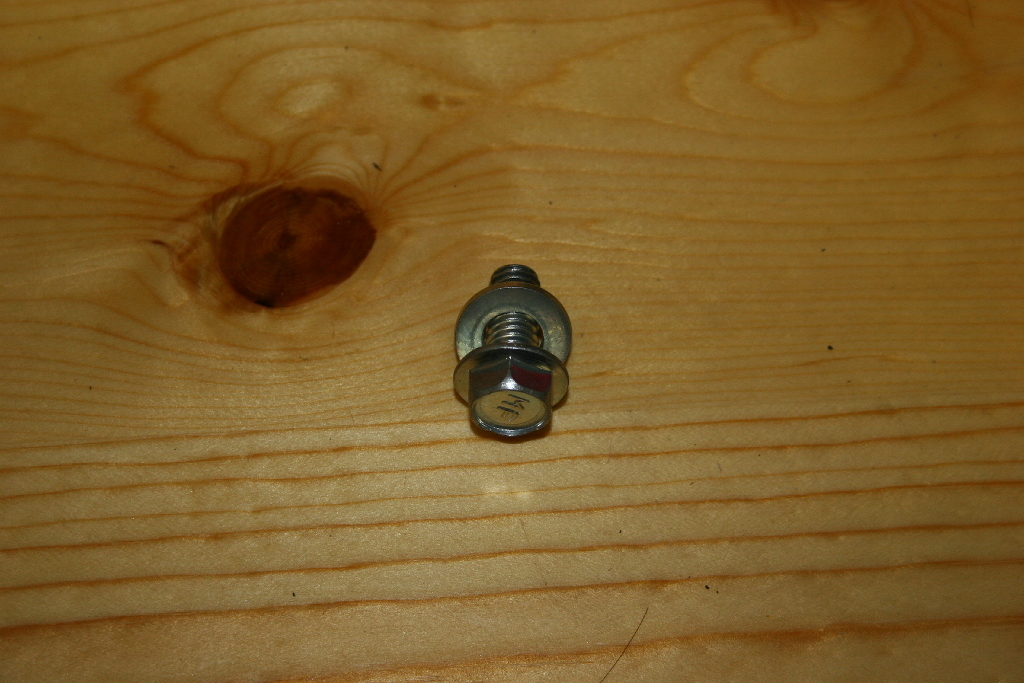
| What you should have for plate and bolts. |
 |
|
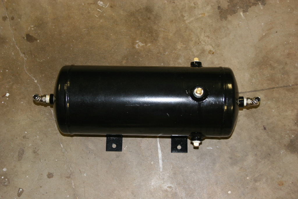
| Heres where it goes and a basic idea of how the tank looks on the plate. The plate is drilled for both size tanks. I am using the 1.75gallon tank. |
Plate goes here. |
What it looks like.
|
1. Loosen evaporator bolts with a 16mm socket, |
 |
 |
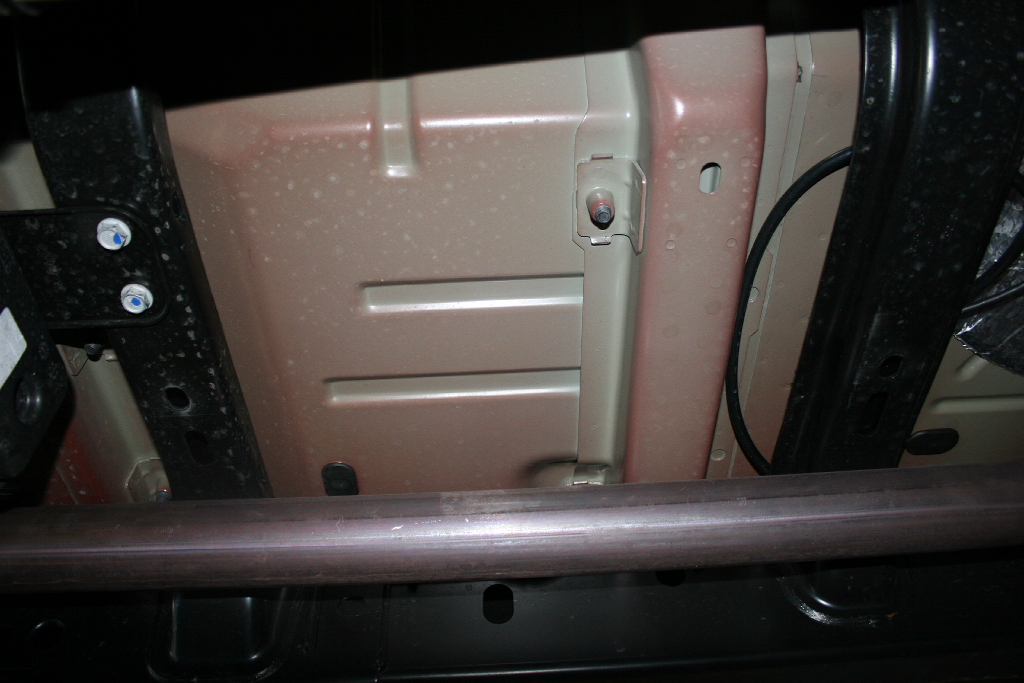
2. Slide the air tank mount plate in between. Keep the inboard slot in plate towards the frame rail.
NOTE: If you have a SWB model, install Evap relocator and then install airtank mounting plate using evap canister mounting locations. |
 |
| 3. Tighten the Evaporator bolts, ensuring that the mouting plate is squared on the crossmembers. |
 |
 |
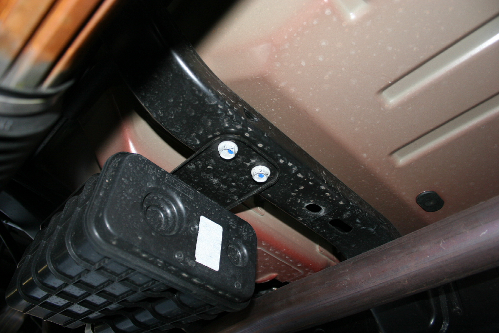
| 4. Using the plate as a template. Drill two 11/32“ holes in the forward cross member. |
 |
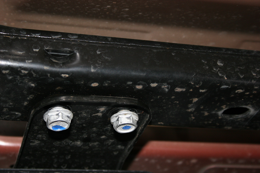
| 5. Insert supplied self tapping bolts and washers. I used a 14mm socket on the bolts since it was a tighter fit. Work the bolts in a little, then out, back in once you get them to bite on the metal. Take your time and go slow, you do not want to snap one of these self tapping bolts off in the crossmember. |
 |
6. Remove the plastic plugs that are installed in the boss's. |
 |
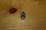
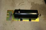
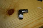
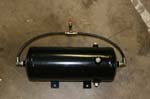
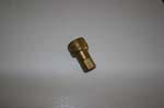
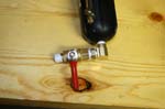
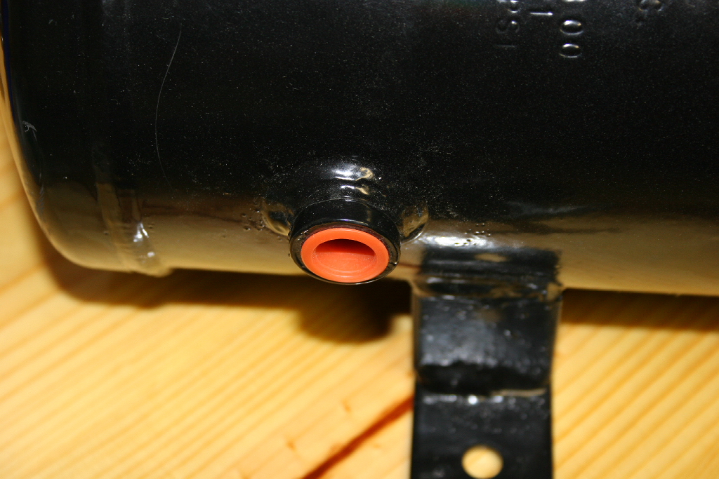
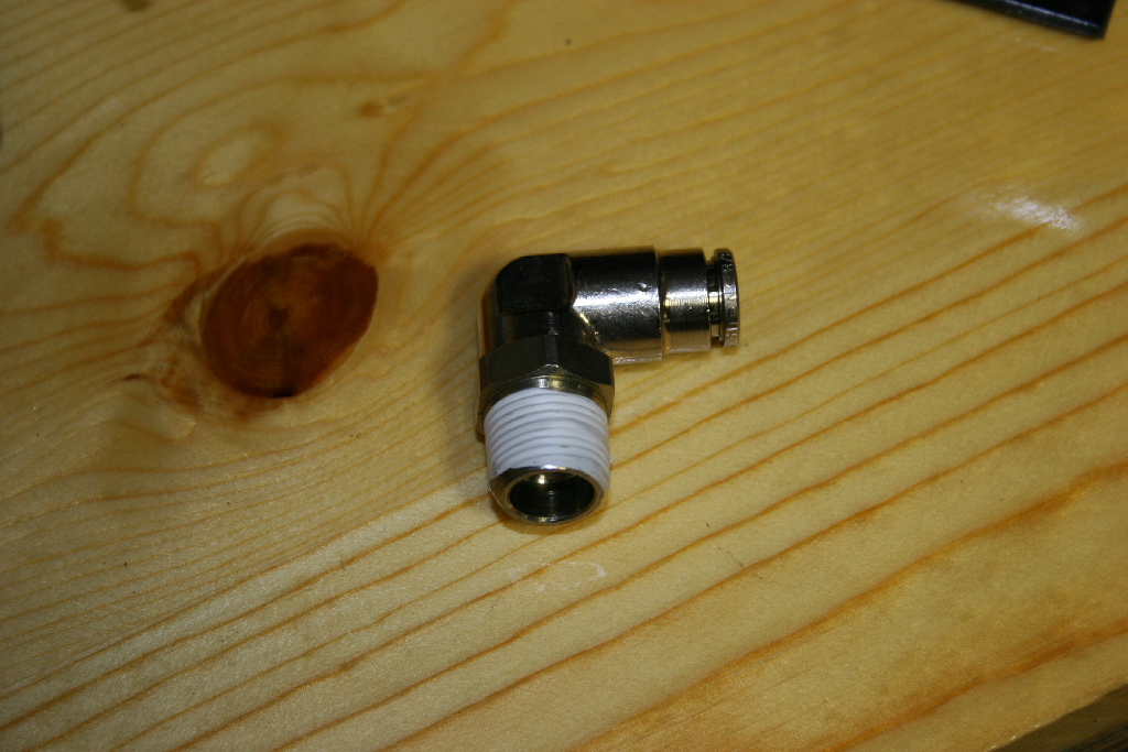
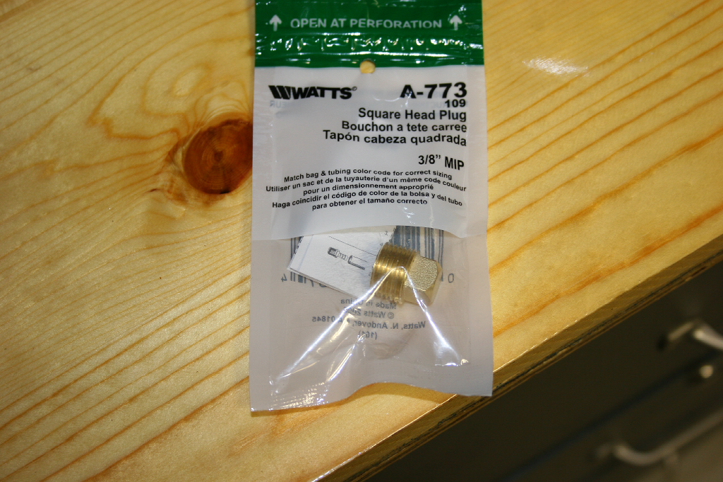
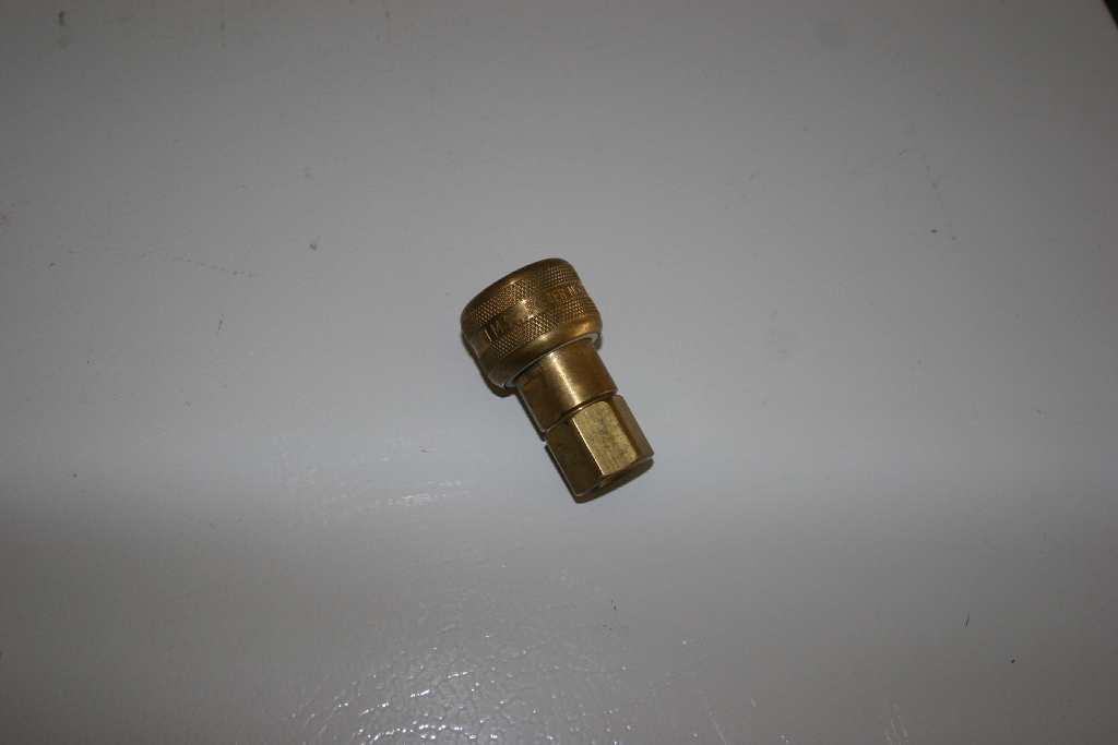
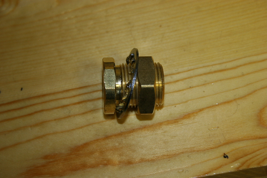
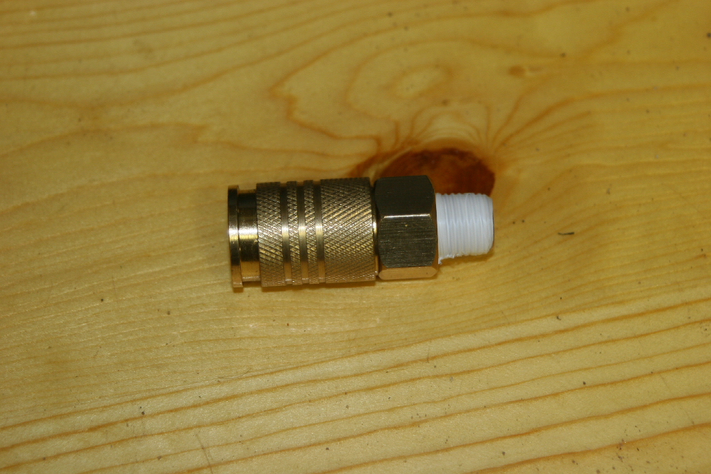
| 7. Install fittings on air tank. Plug the unused holes. Use socket head plugs if you can find them. |
 |
 |
 |
| I was able to pressure test the tank with a manifold that I had built for the AiROCK system. This way I could check for leaks before I bolted the tank up in place. |
 |
 |
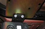
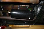
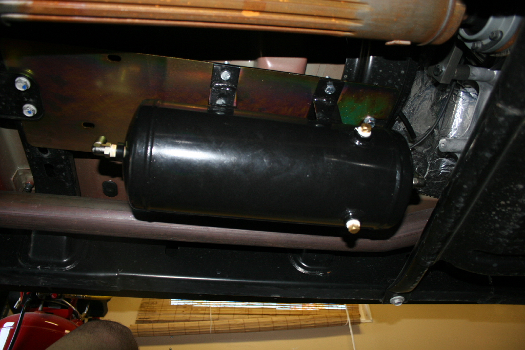
| 6. Install air tank with bottom boss forward on the air tank mounting bracket using (4) 3/8"x1.25" bolts, (8) 3/8" washers and (4) 3/8" nuts. You will need a 9/16" socket and combo wrench. |
|
 |
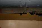
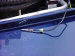
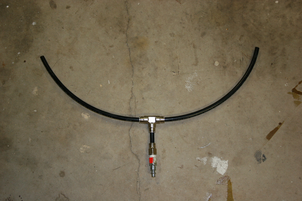
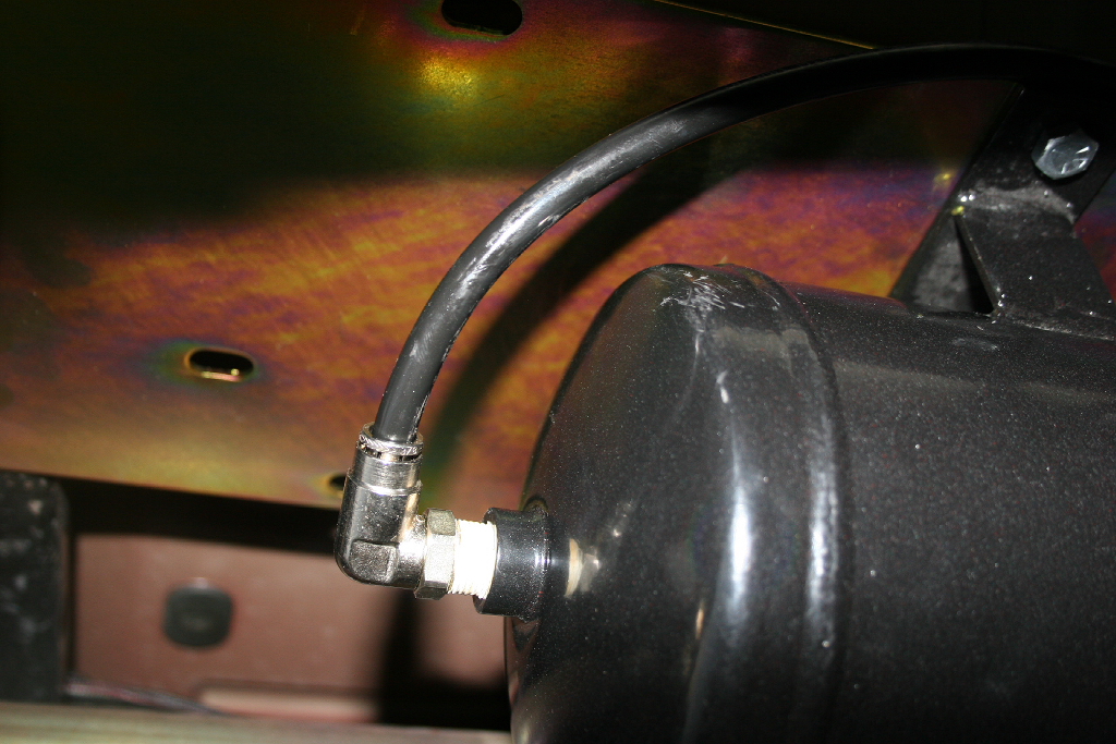
7. If you are using the air couplers. Find a suitable mounting location for the front and rear air coupler and route air lines keeping clear of the exhaust. Kilby recommend routing the line up the frame and over the gas tank keeping clear of the exhaust pipe. |
 |
| Here is what it looks like installed, you can see that the square head plugs that I use hang down just a little. I will replace these with socket head plugs later. |
 |
 |
|
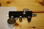
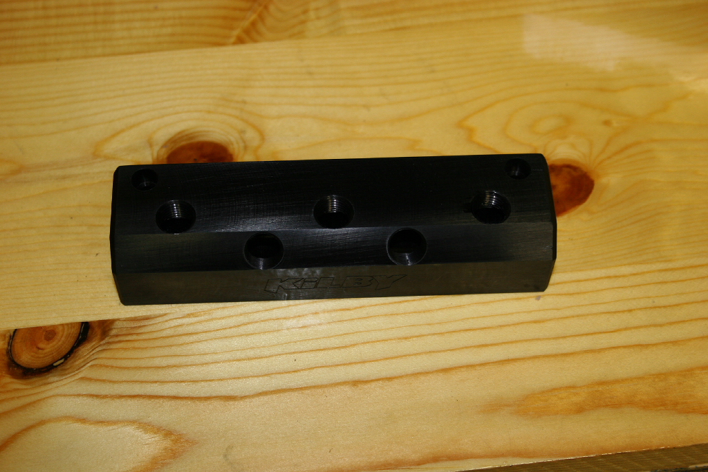
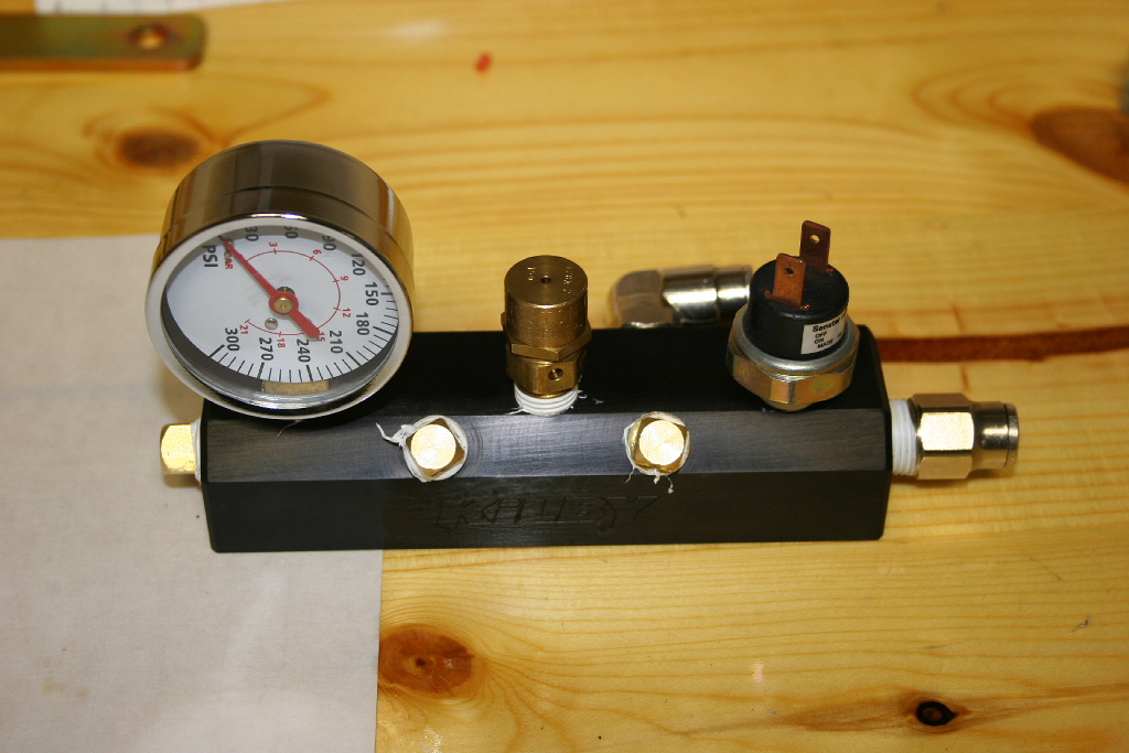
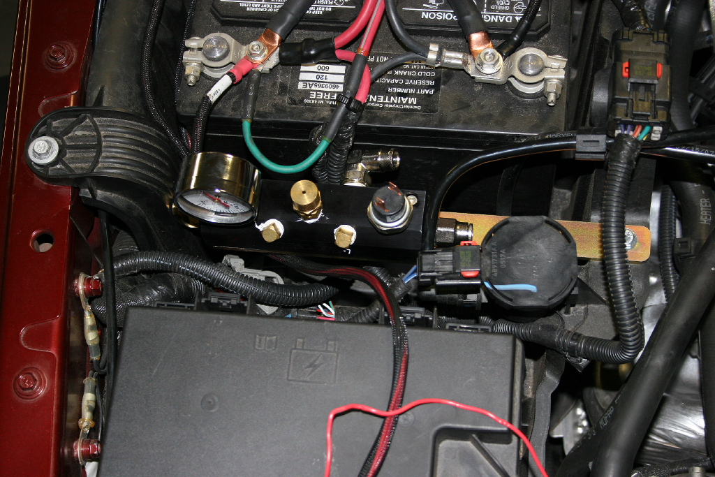
| Manifold bracket installation: |
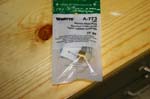
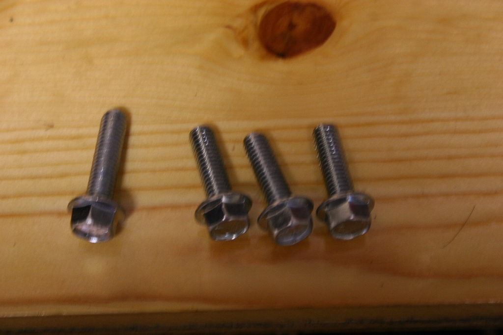
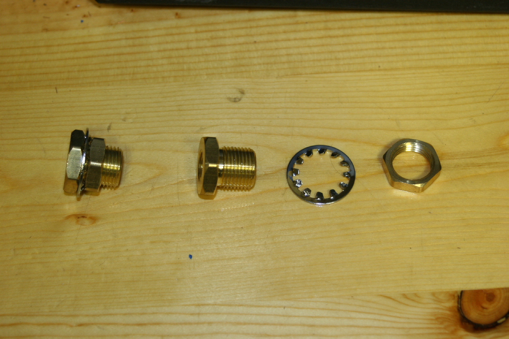
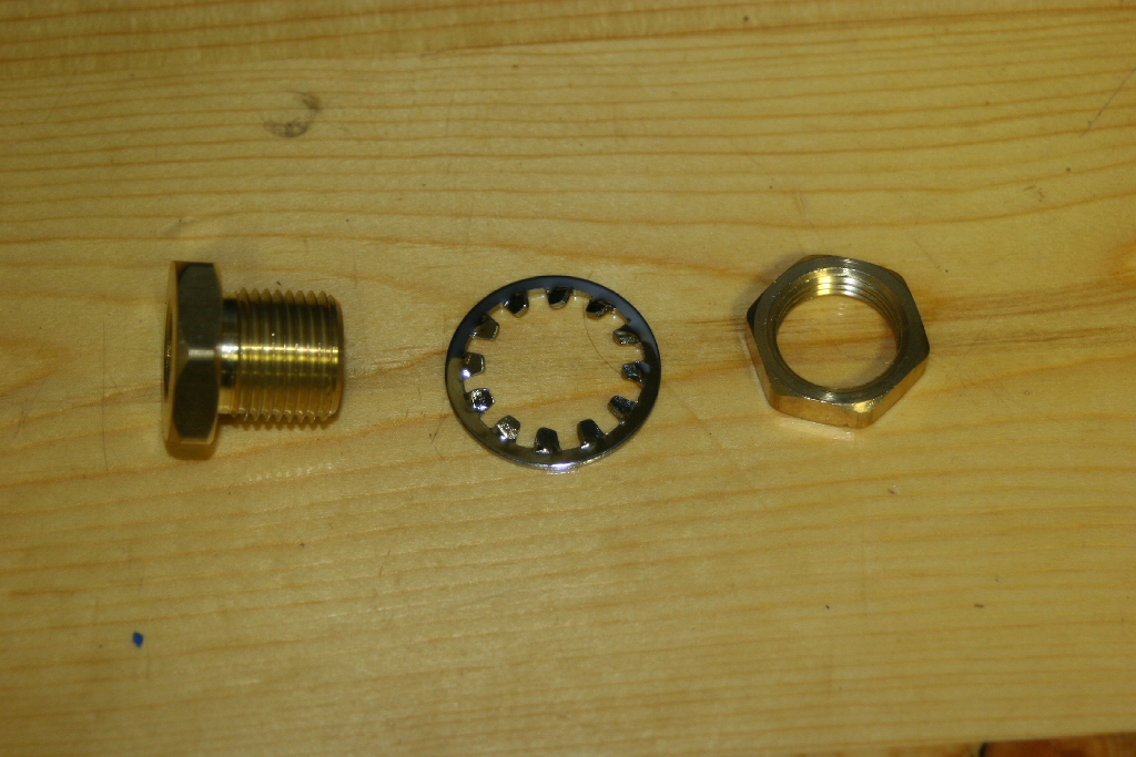
| Parts Needed: |
 |
 |
 |
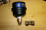
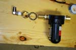
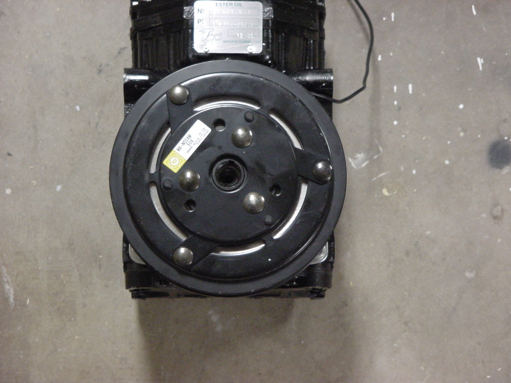
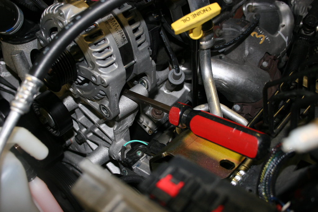
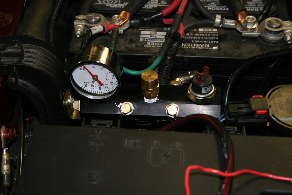
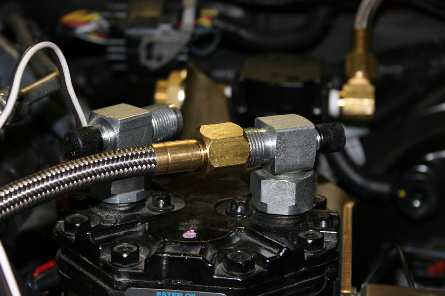
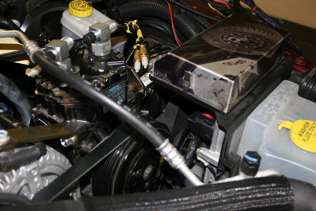
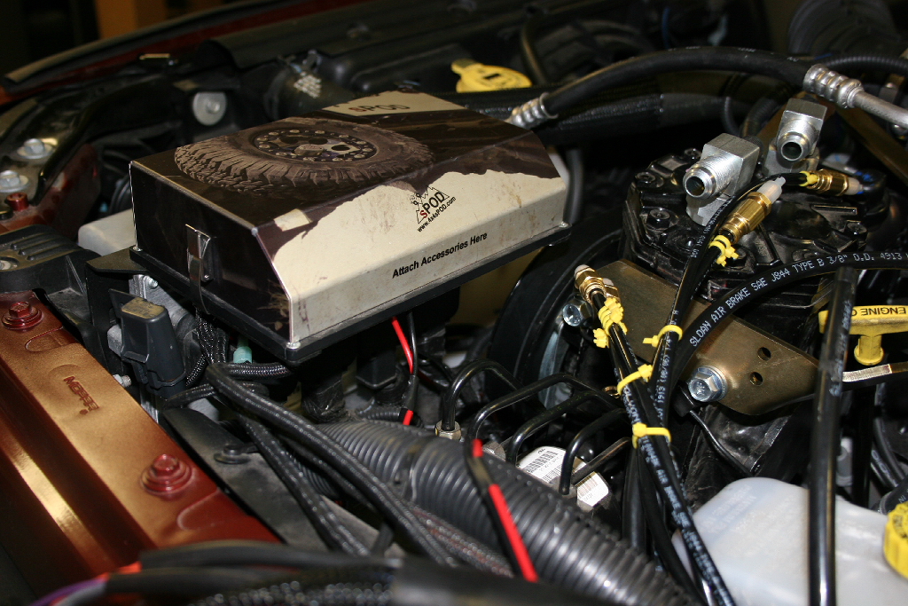
1. Assemble the Mainfold. Make sure you use teflon tape to seal all the threads for each item you install. The mainfold has (3) 3/8" fittings located in the base, one is in the back, and (5) 1/4" fittings on top. I plugged 2 of the 1/4" fittings, and the other 3 received a pressure gauge, the relief/safety valve, and the pressure switch.
Note: My system was installed to provide air for an AiROCK suspension so will vary slightly on fittings. |
 |
 |
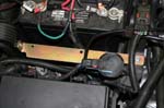
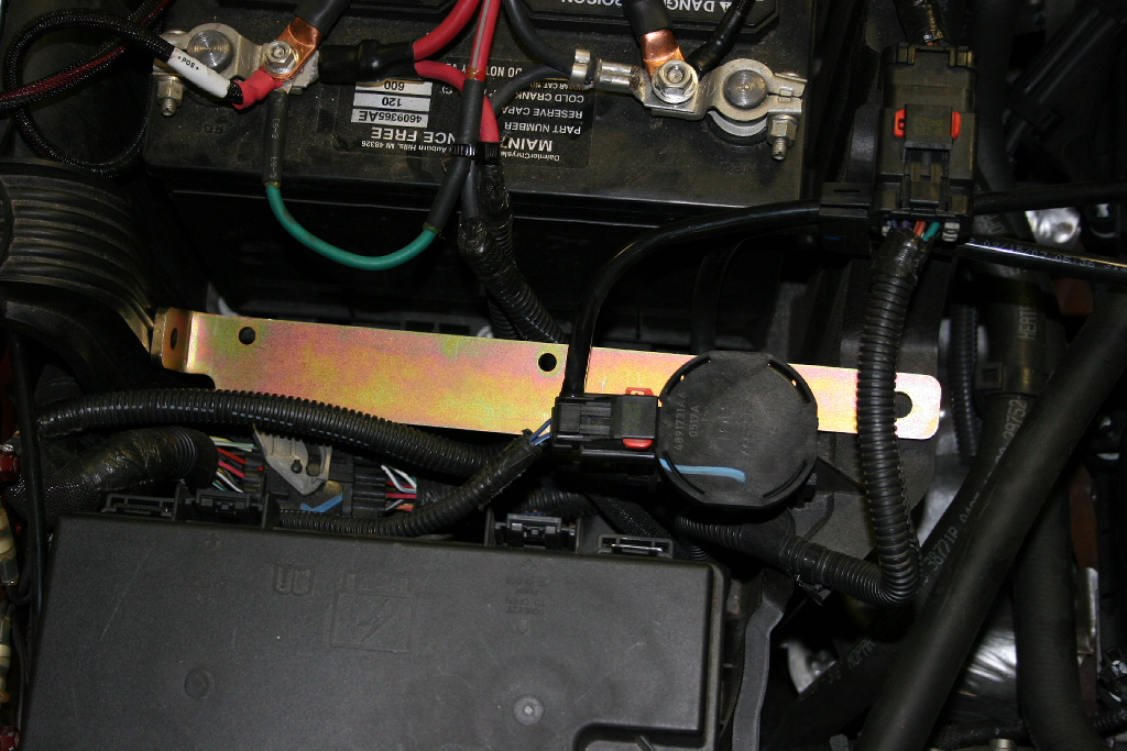
| 2. The Manifold bracket installs in front of the battery. |
 |
| 3. Position the bracket as shown. Mark the plastic bracket on the passenger side fender. |
 |
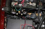
4. Drill a ½” hole for the supplied well nut in plastic bracket on the passenger side fender. Insert the well nut. |
 |
 |
| 5. Install the 1/4" x1" bolt and 1/4" washer through the bracket and into the well nut. |
 |
| 6. Mark the other side of the battery box. Drill a 5/16" hole in the battery box. I just pushed the bracket aside after I marked the hole and drilled it. |
 |
 |
7. Install the 1/4"x1 bolt, (2) 1/4" washers, and 1/4" nut through the bracket and into the box. |
 |
| 8. Install the assembled manifold with (2) 10/32” x 1 1/2” Socket Head Bolts and (2) 10/32” Hex Machine Screw Nuts. These can be a little hard to install. |
 |
 |
| |
| Hooking it all together: |
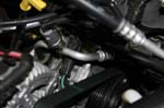
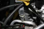
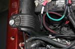
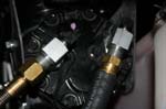
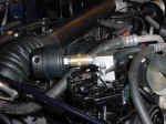
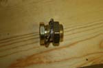
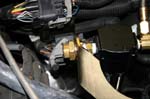
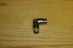
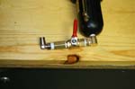
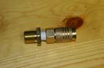
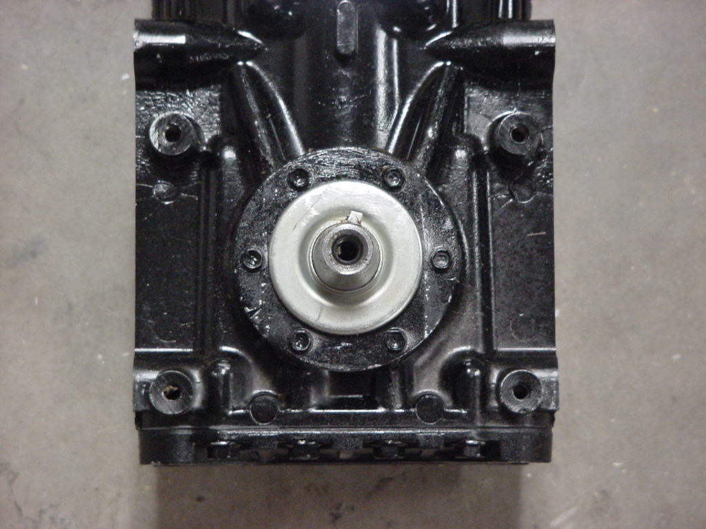
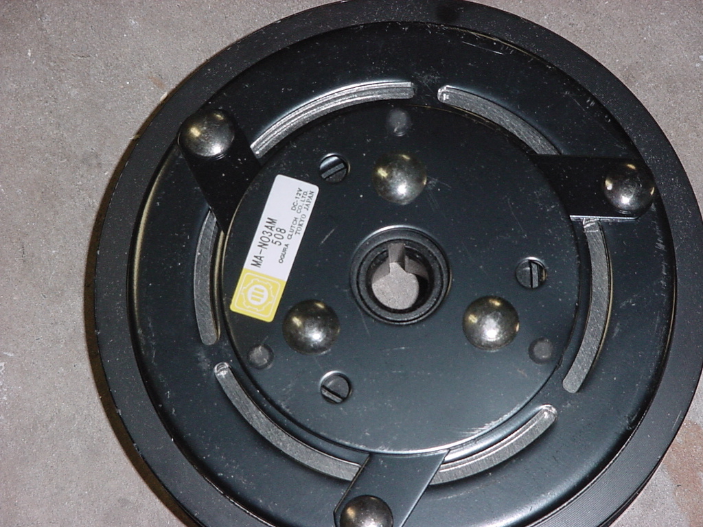
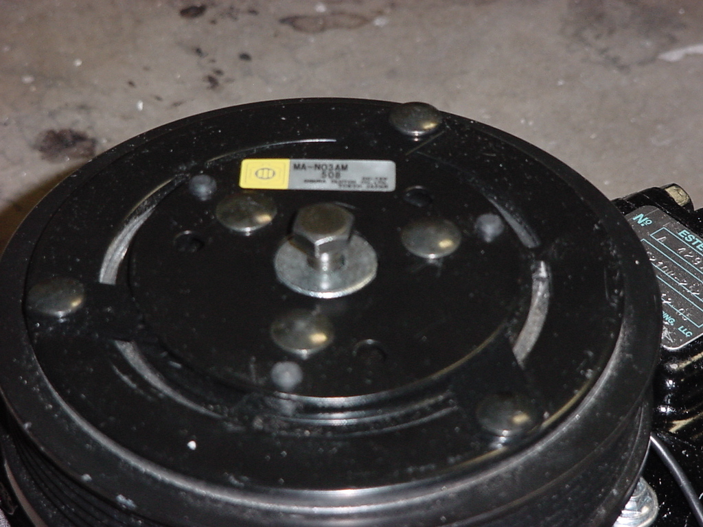
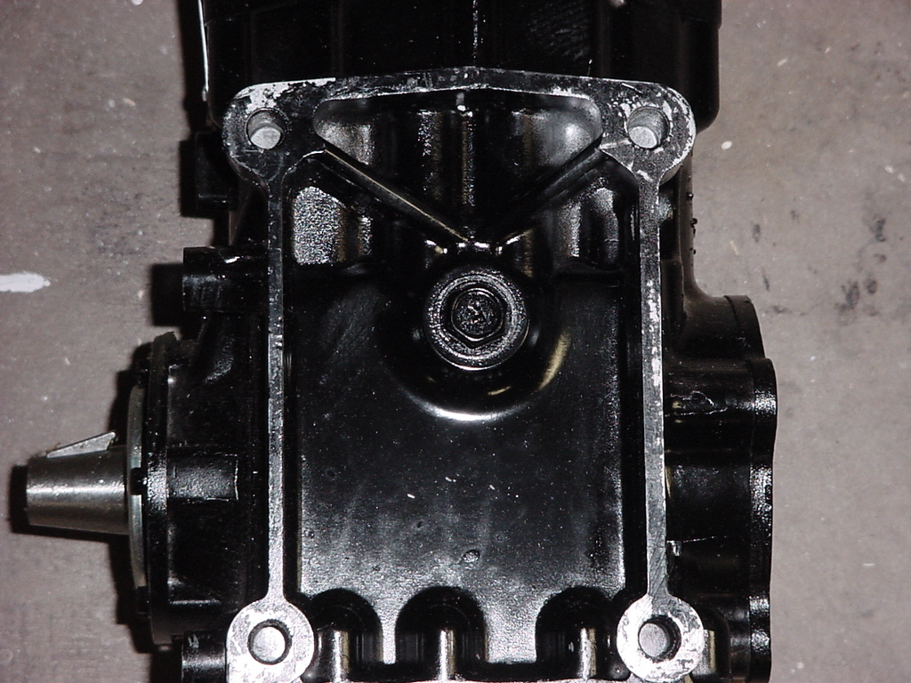
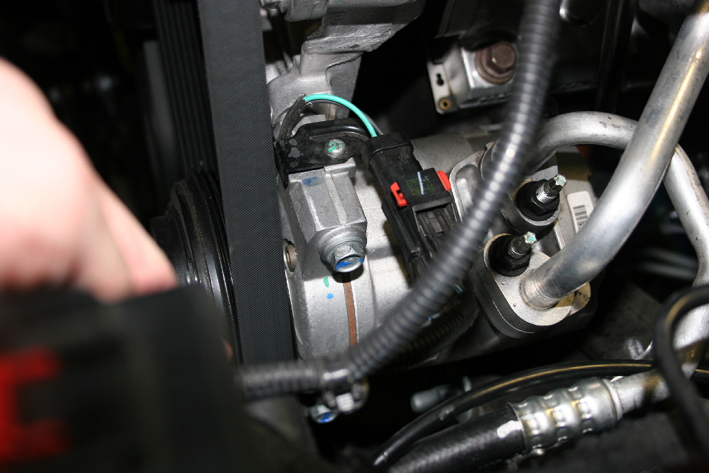
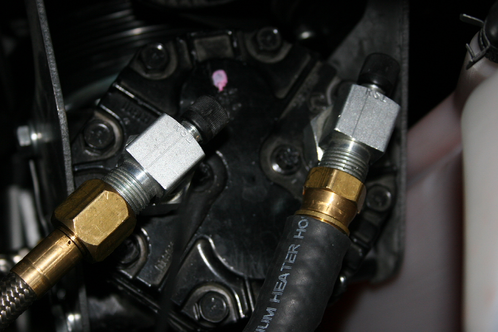
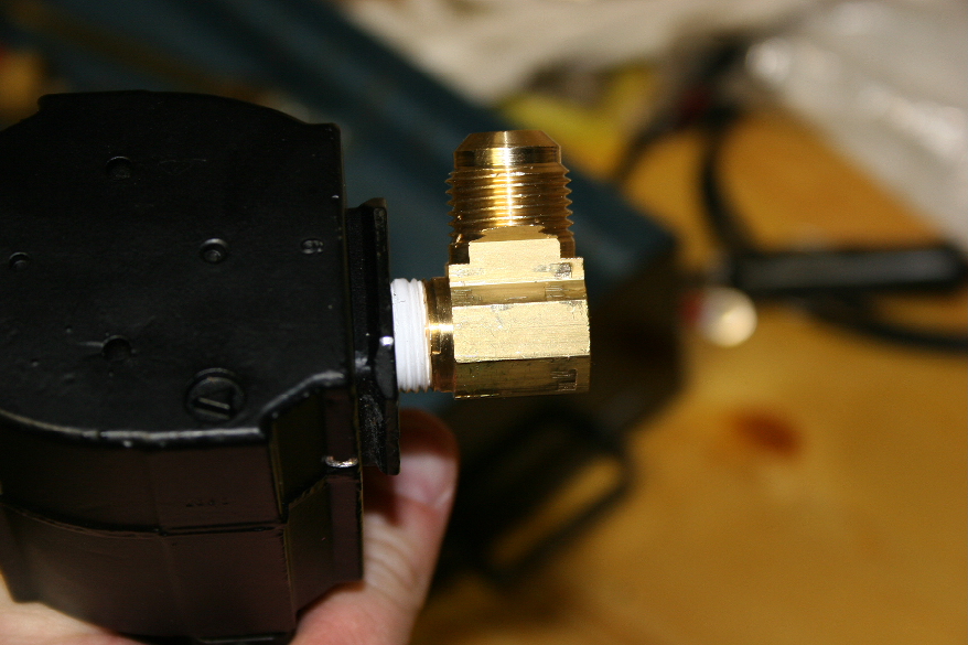
1. Attach flange fittings or rotolock fittings to suction and discharge ports on top of compressor. The ports are marked with a S (Suction) and D (Discharge). |
 |
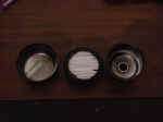
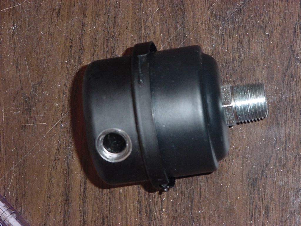
| The
Kilby's air filter. I opened it up just to make certain that
there was nothing inside of it. |
 |
 |
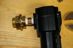
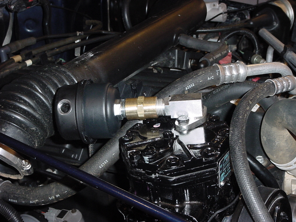
2. Attach air intake filter to suction port. You will need a 7/8" Combo Wrench and a 12"
Adjustable Wrench. I didn't use this type of filter so the picture actually shows a TJ's engine compartment, the filter will point towards the back of the compartment. |
 |
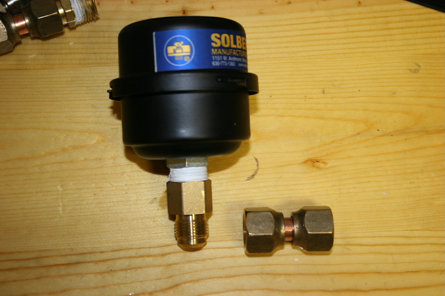
| I needed to make a slight modification since my rotolock fitting were set up for hoses. |
 |
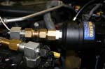 |
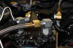
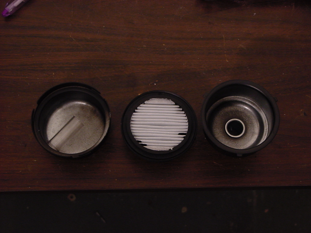
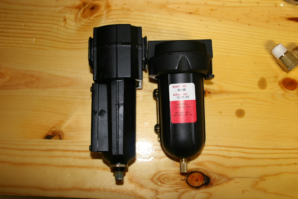
| 3. Screw the check valve into the outlet of the coalescing filter and then screw the bulkhead fitting onto the check valve. The nut and washer on the bulkhead fitting will go on the side away from the coalescing filter. This is the coalsecing filter from ORO. Kilby's is smaller and rated for a higher temperature. I switched later to Kilby's filter. |
 |
 |
| Kilby filter next to the Off Road Only filter. |
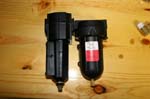 |
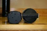 |
| Same parts layout. |
 |
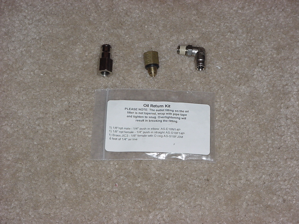
| 4. Install the oil return fitting on the bottom of the coalescing filter. I was using a filter with an auto drain, so just installed a fitting. Install the inlet fiting to the coalescing filter. I used a 90degree since I had a longer hose from ORO vs a straight fitting if I would have used all of Kilby's setup. |
 |
 |
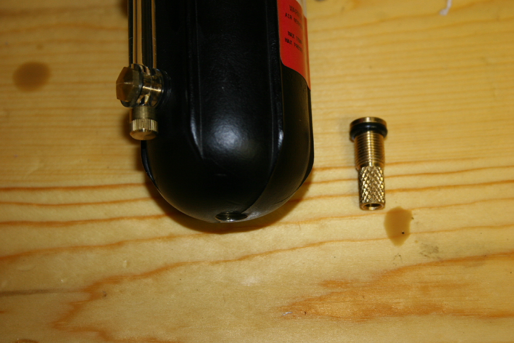
| On the Kilby filter you will need to remove the bottom drain plug and install the manual drain kit. The drain screws into the filter to remove. Mine is slighly different than Kilby's kit, since I used some parts I had in the drawer. Basically 1/8" MPT elbow, adaptor and a 1/4" drain valve. |
 |
 |
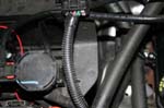
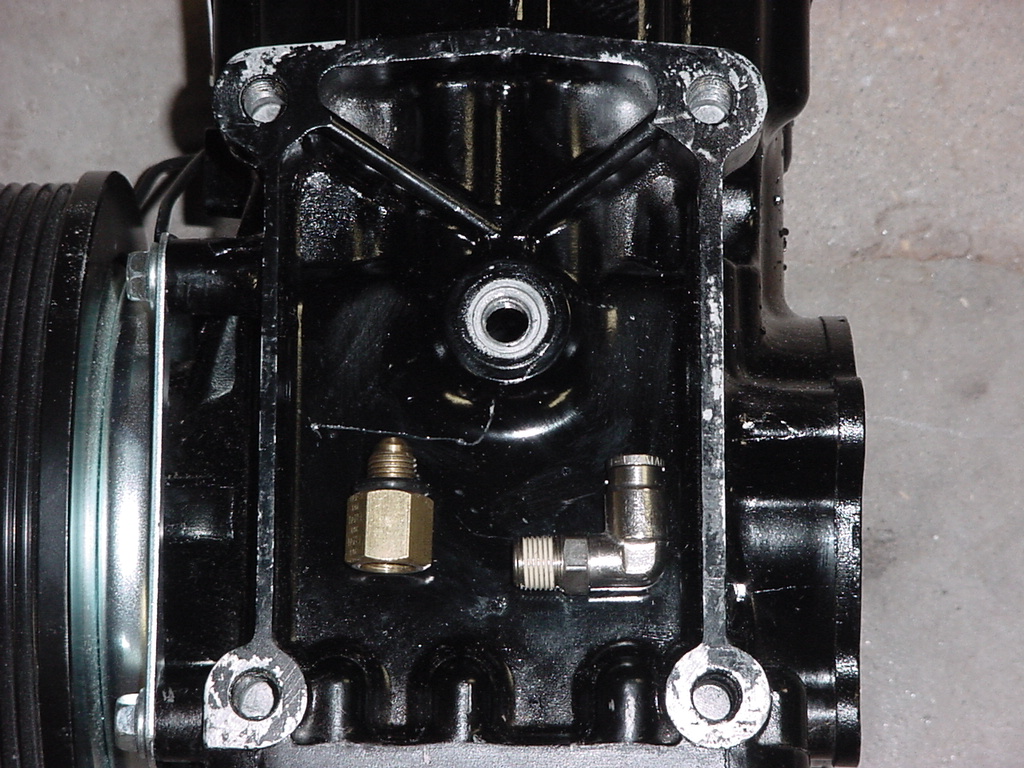
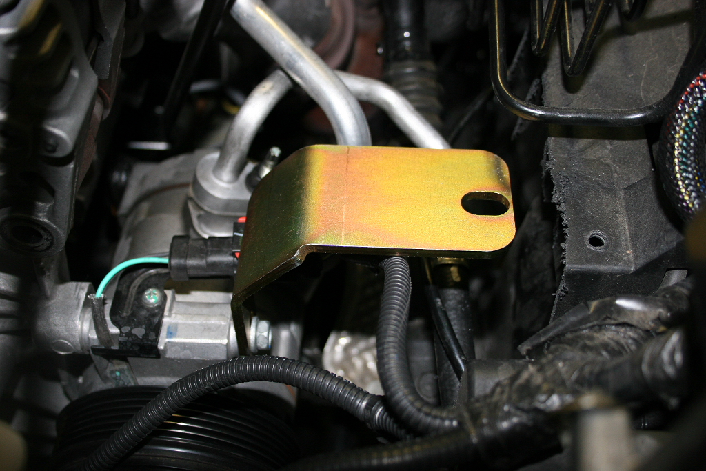
3. Using supplied bracket,Attach coalescing filter to the side of the compressor. |
|
 |
4. Attach air line to discharge port. Route the discharge line to intake of coalescing filter. |
 |
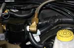 |
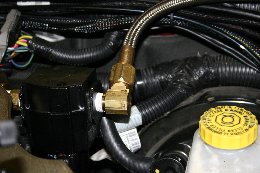
| 5. From the discharge of the coalescing filter, route air line to the Air tank |
|
|
| 6. From the air tank route the air line to the air manifold. |
|
 |
| 7. If you are using Kilby's manual oil return system. Attach the valve to the bottom of the coalescer filter and route back to the compressor. |
 |
 |
| |
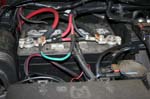
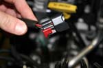
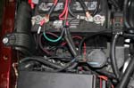
| Electrical Connection: |
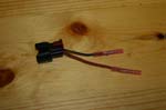
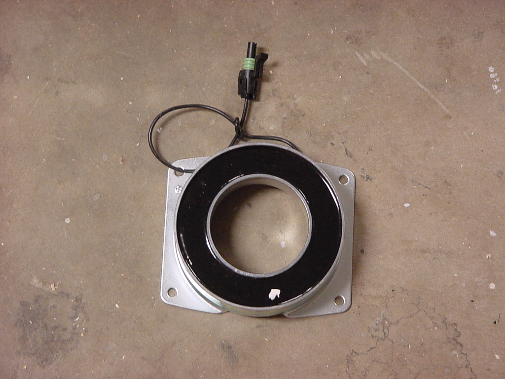
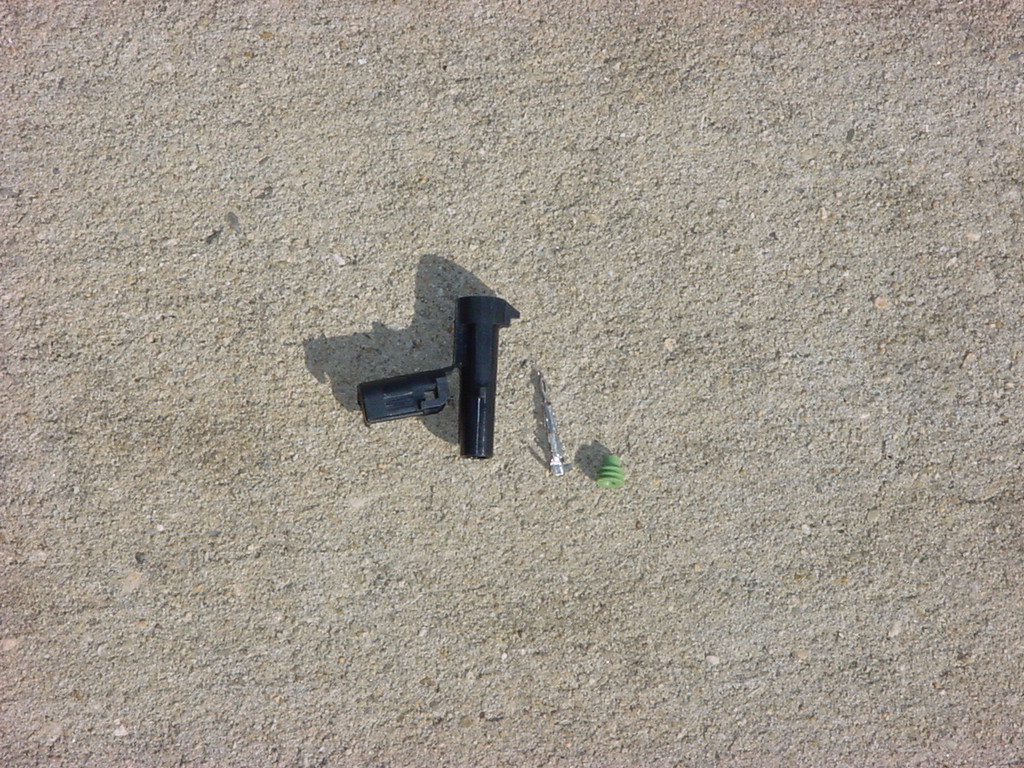
| 1. The
kilby's compressor came with a fitting on it to hook up electrical
power for the clutch. Now you could easily just cut this fitting
off and connect straight into the wire, but I liked the idea of being
able to disconnect the compressor if I needed to remove it.
So a quick trip to Pep-Boys netted me the other side of the connection.
I also wanted to be able to turn off the clutch just incase something
happened, like the pressure switch failing or a line blowing. |
 |
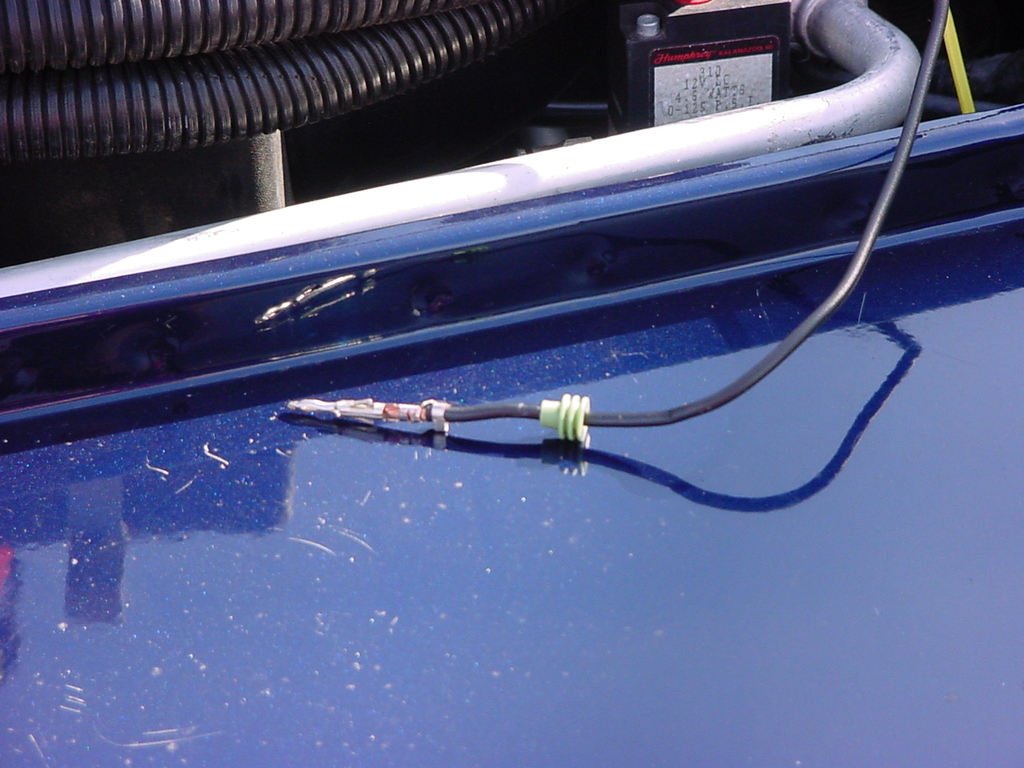
| 2. Insert
the rubber plug onto the wire, then crimp the end on to the wire.
Insert this into the plastic housing and close the end cover. |
 |
| 3. Connect
the fittings together. |
 |
4. There are a few different ways to power the compressor.
- Switchable power, On/Off Switch, pressure switch, compressor
- Switchable power, On/Off Switch, pressure switch, relay, compressor.
- sPOD, pressure switch, compressor
- AiROCK for the JK's does not use a switch, it operates the compressor slightly different, so that the compressor comes on when you trigger AiROCK's mode changes, it does not wait for the pressure switch to activate.
|
| 5. Find a suitable location for your switch inside the jeep and connect the wires as described above. |
|
| |
| Air Hose Fittings: |
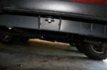
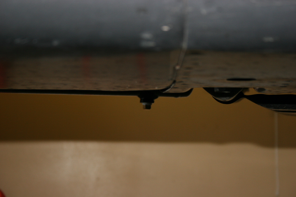
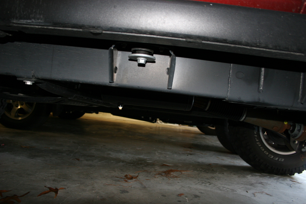
| I am waiting on my bumpers before I install these. I have seen a few options on locations to mount these. Inside the cab at each of the front doors, behind the grill, in the rear fender well to name a few. I intend to drill a hole and mount these to the front and rear bumpers. |
 |
 |
 |
 |
| |
| Completion: |
| 1. Start engine, check for leaks. You now have onboard air! |


