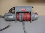
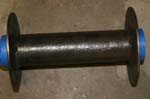
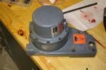
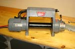
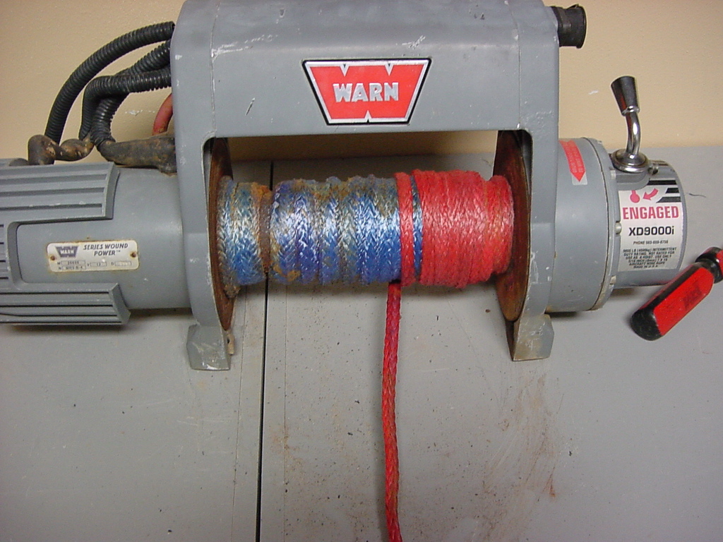
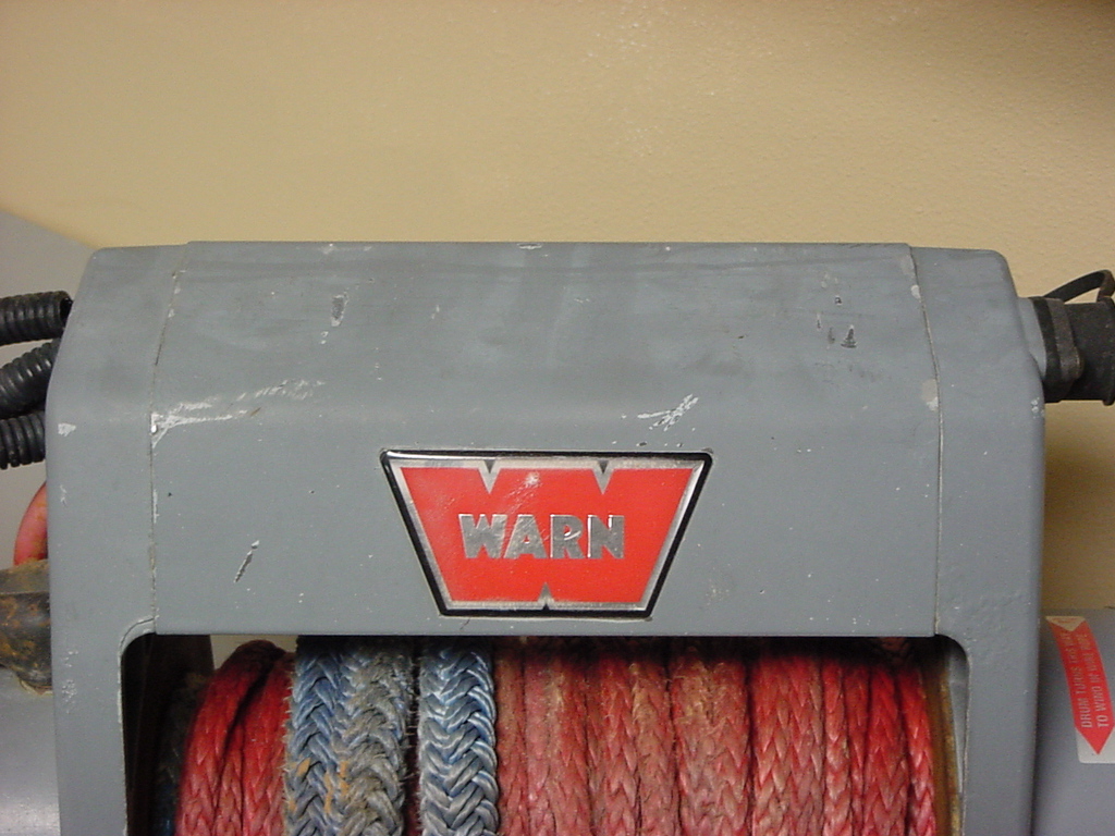
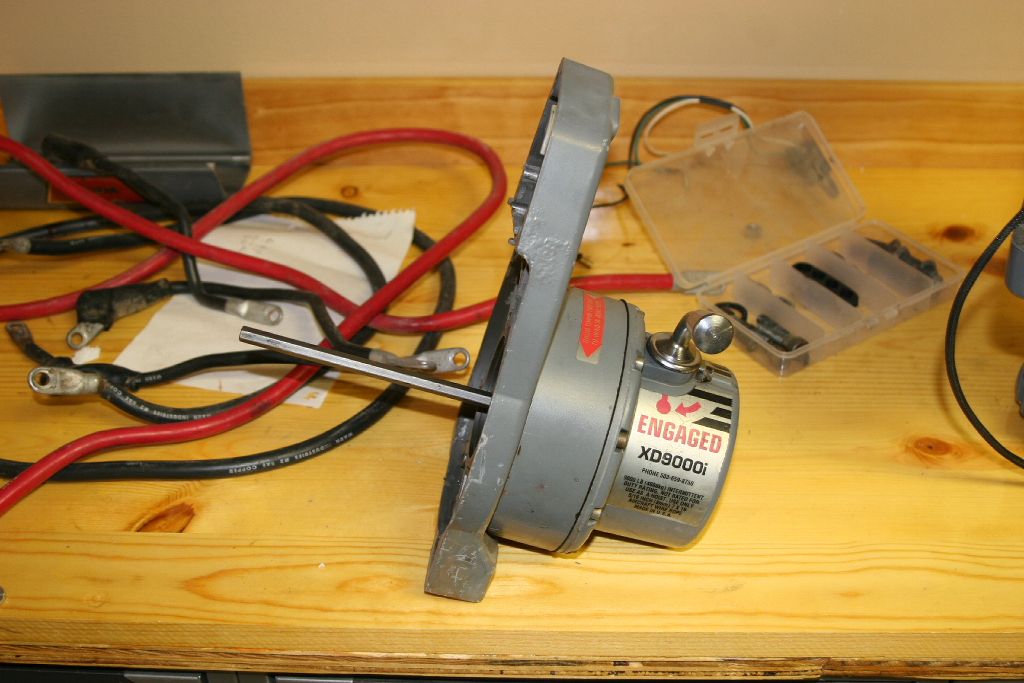
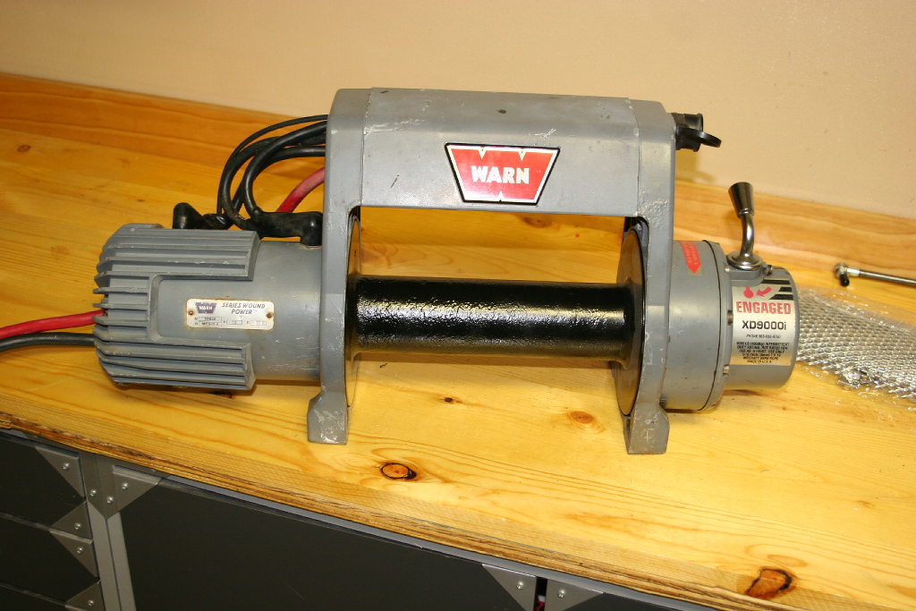
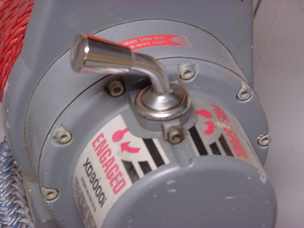
My Warn xd9000i has been on the front of many of my Jeeps over the years. I have taken it apart and regreased it in the past, and I figured it was due for another dissassembly and rebuild again now that I had the Jeep Wrangler JK. The winch was pretty filthy and the synthetic winch line had definately seen better days. So I looked around to see where I could get rebuild parts for it on line. I came across www.warnserviceparts.com. Now I'm not providing a clickable link to them for the simple fact their customer service was worst then terrible. I order a few gaskets and seals from them. They shipped me the wrong box, then never shipped me the correct parts, I had to call them, and got the "Owner" who promptly didn't remember ever talking to me about things, then when I repeated her conversation she said she would check into it. She called me back and said she was sorry and didn't have any employees to blame this mistake on. The owner blaming an employee for a mistake and telling a customer that. In all it took me almost 3 months to get $12 worth of parts, not a place I will or would recommend doing business with. Since then Mike at www.4x4rockshop.com has become a certified Warn dealer and can get repair parts to you. I've done a lot of business with Mike and have always gotten excellent service. I know who I'm going to use next time I rebuild a winch.
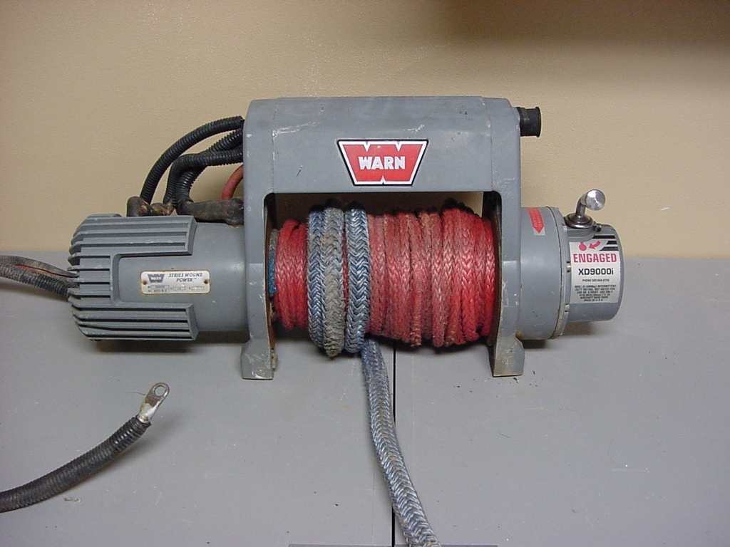
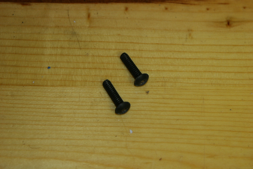
| I've had this warn winch dating all the way back to my 91 YJ. It's seen it's fair share of recoverys, dunkings, and even landscaping projects over the years. I rebuilt it a while back after it was underwater for a while and was still dripping the next day. This would be it's second rebuild over the time. I also wanted to see how well the gears were holding up after everything. Make sure you have a container to put all the screws and nuts you take off into. You don't want to lose anything, some of these are hard to find. |
 |
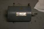
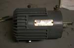
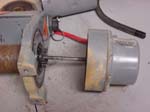
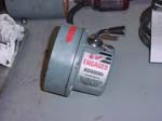
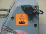
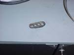
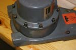
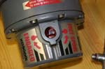
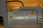
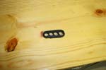
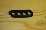
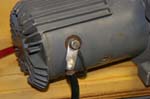
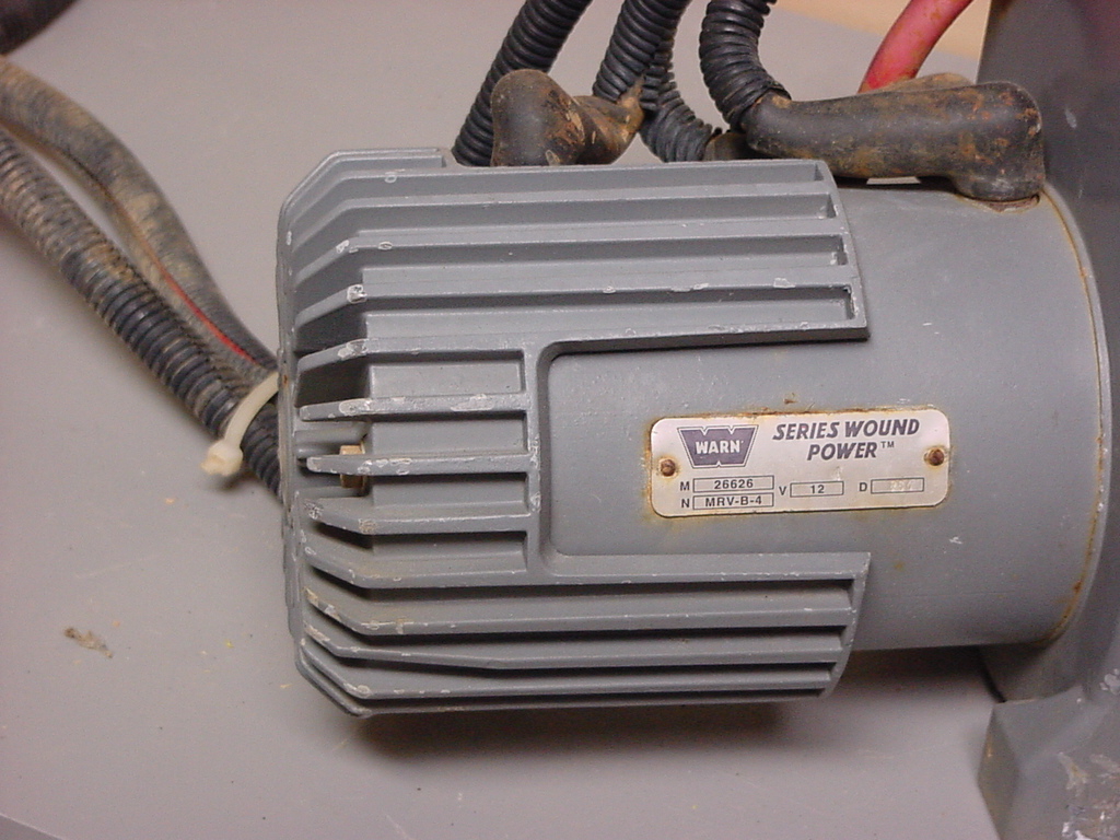
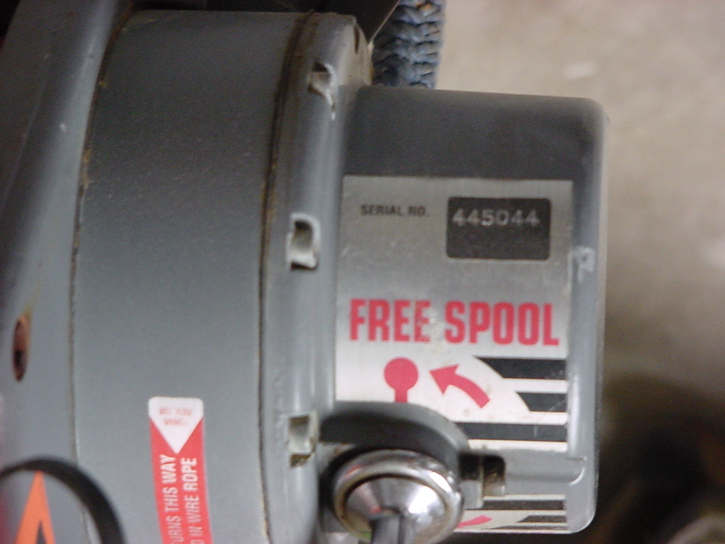
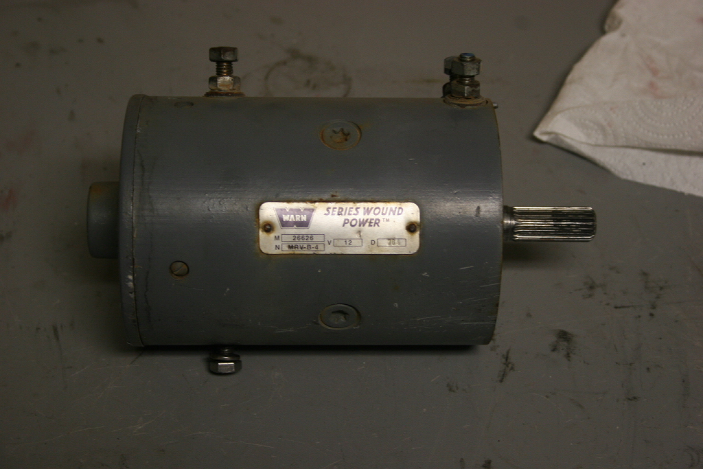
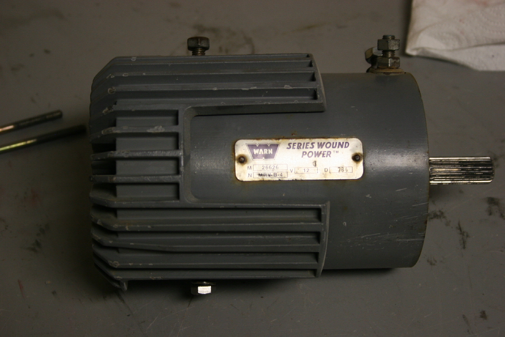
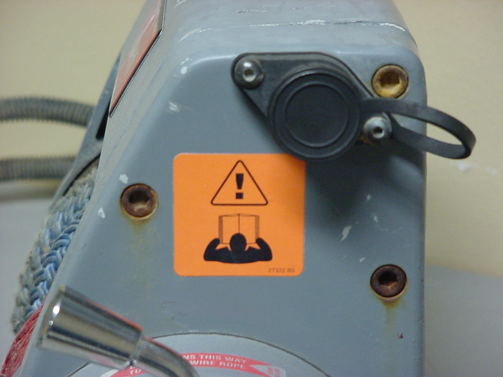
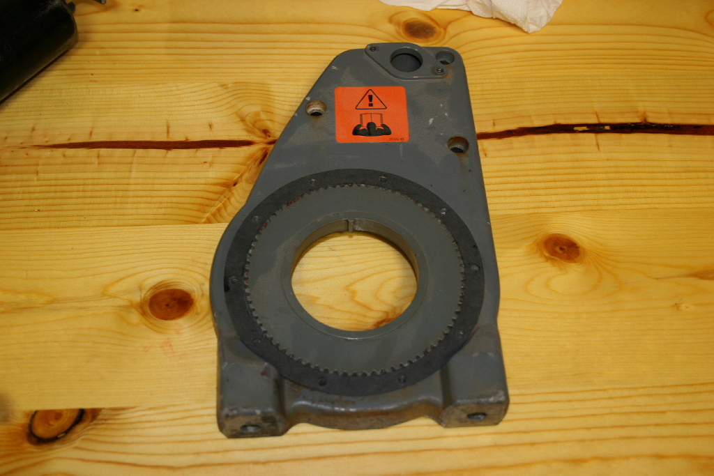
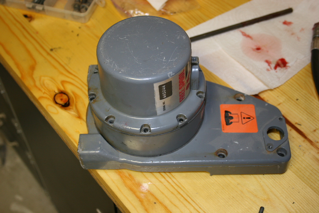
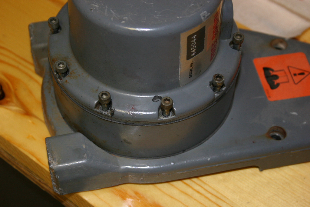
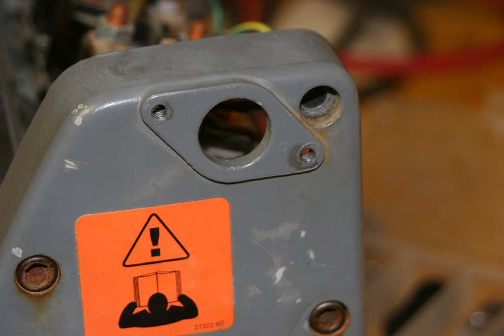
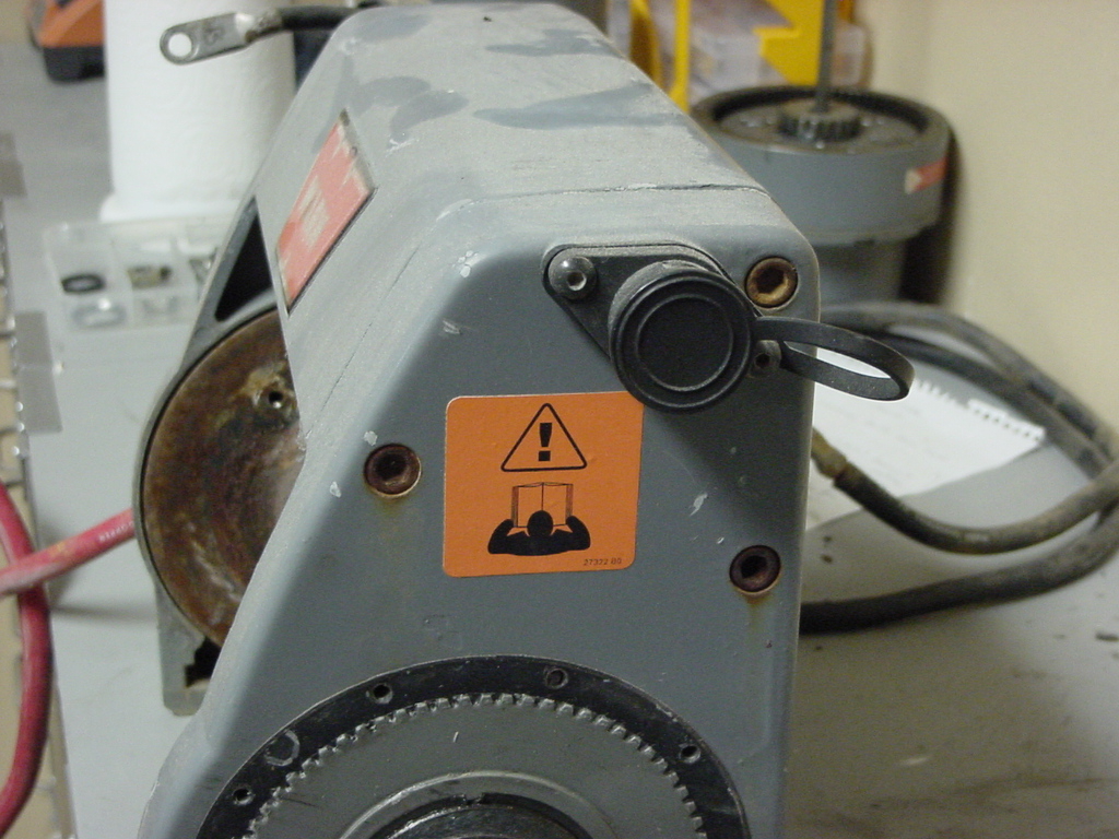
| There are two label plates on the winch that you will or may need. One is on the motor with the motor information. The second is the serial number which will give you the correct parts list to look at. |
 |
 |
| |
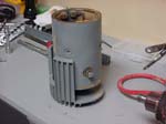
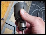
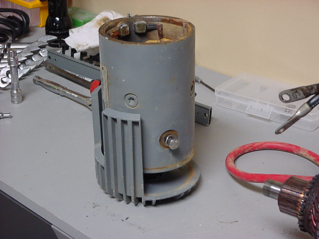
| Dissassembly of the motor: |
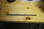
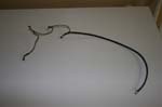
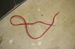
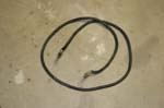
| 1. Pull out and remove the cable or robe from the winch drum. I had to pull the last few layers apart to get the synthetic line off. I don't know if the line is reuseable or not at this point, I need to clean it up and drop it off to my buddies at the harbor to take a look at. |
 |
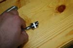
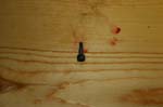
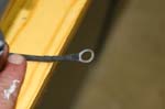
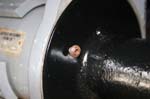
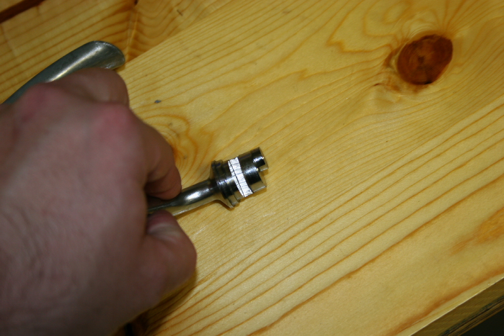
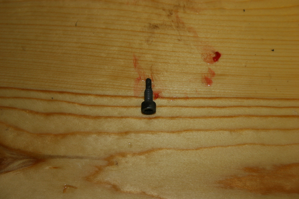
| 2. Remove the end of the cable by removing the retention screw. Mine was held on with a 5/32 " allen head screw. |
 |
 |
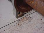
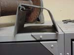
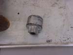
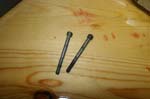
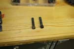
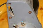
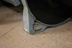
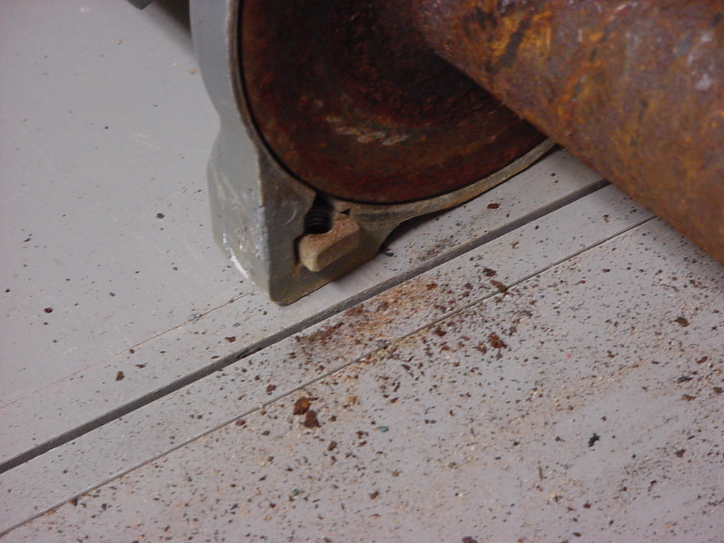
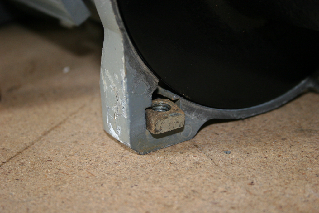
| 3. Remove the square nuts from the feet of the winch. Mine were crusted in so you may need to dig them out with a scribe. |
 |
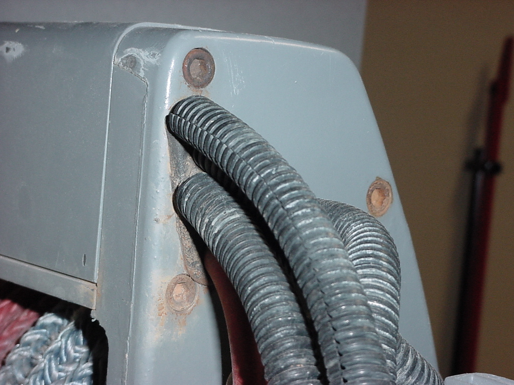
| If you put any wire loom over you cables to protect them, you will need to remove them. I don't know if I will put them back on, they just seemed to collect all sorts of dirt. |
 |
 |
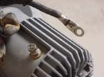
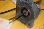
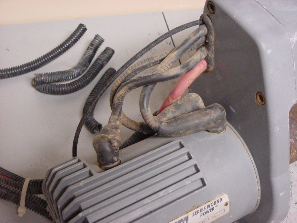
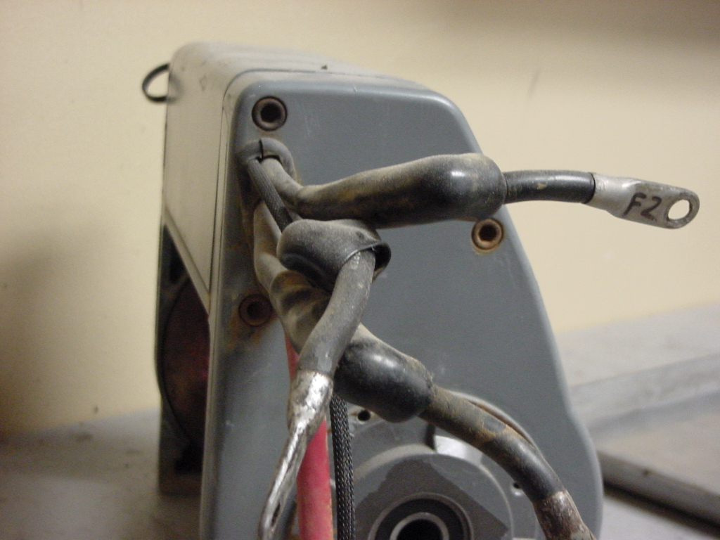
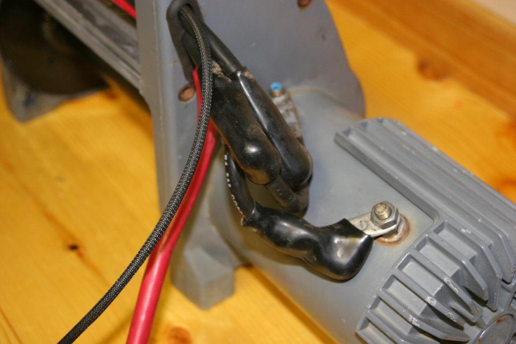
| 4. Pull back the rubber boots protecting the terminals on the motor. |
 |
 |
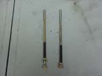
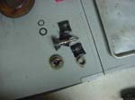
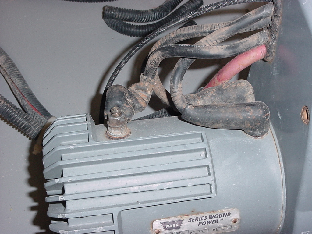
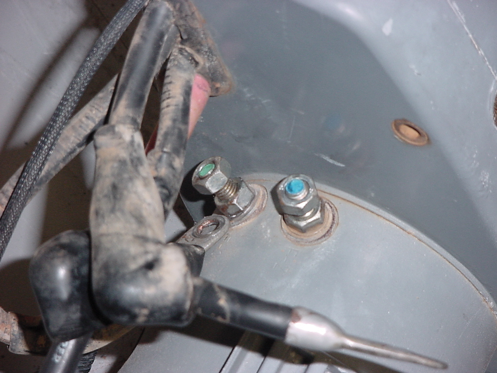
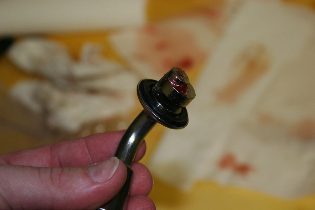
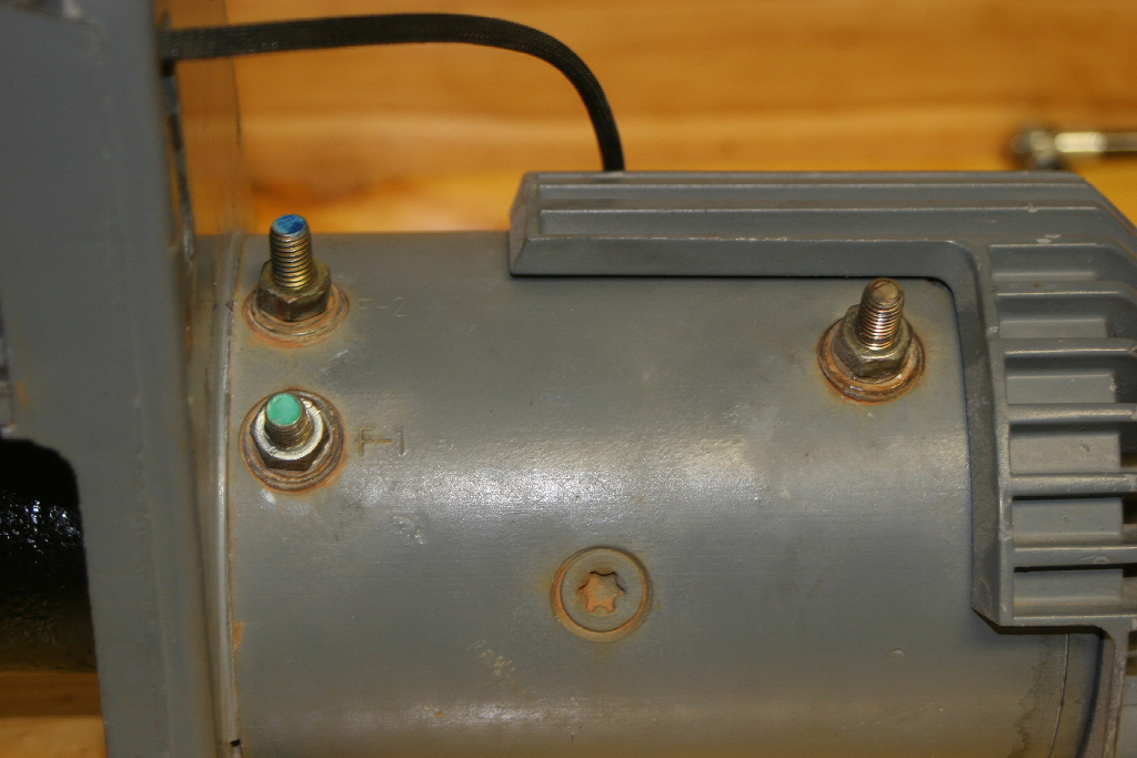
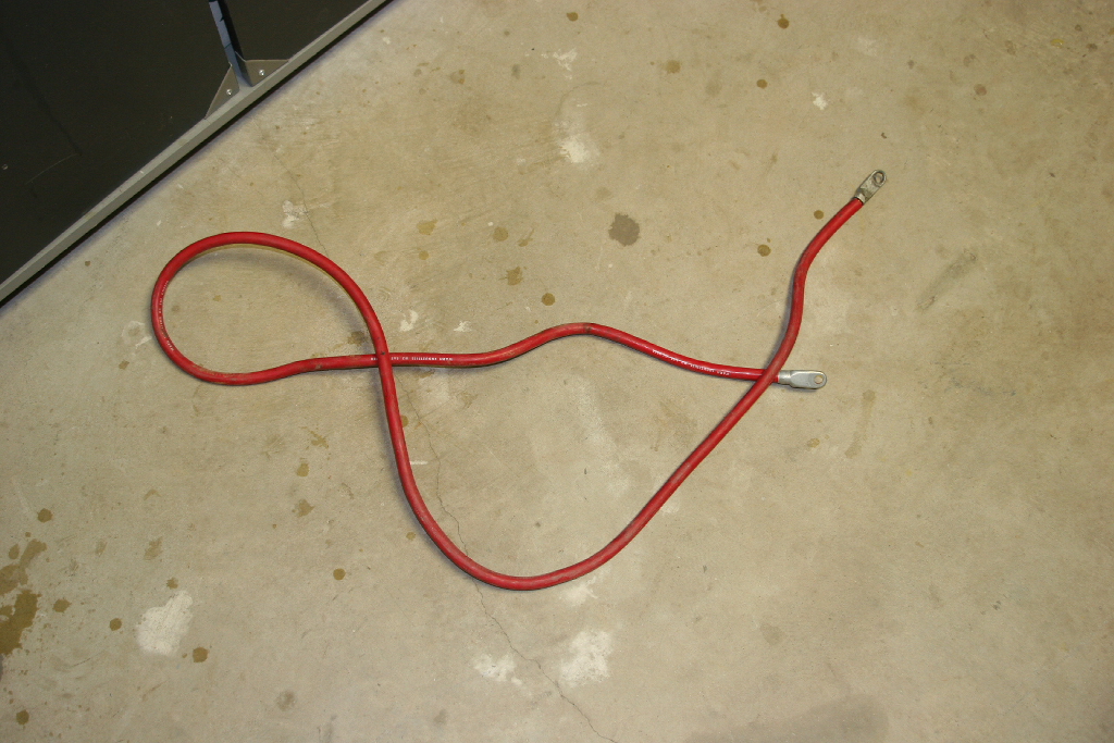
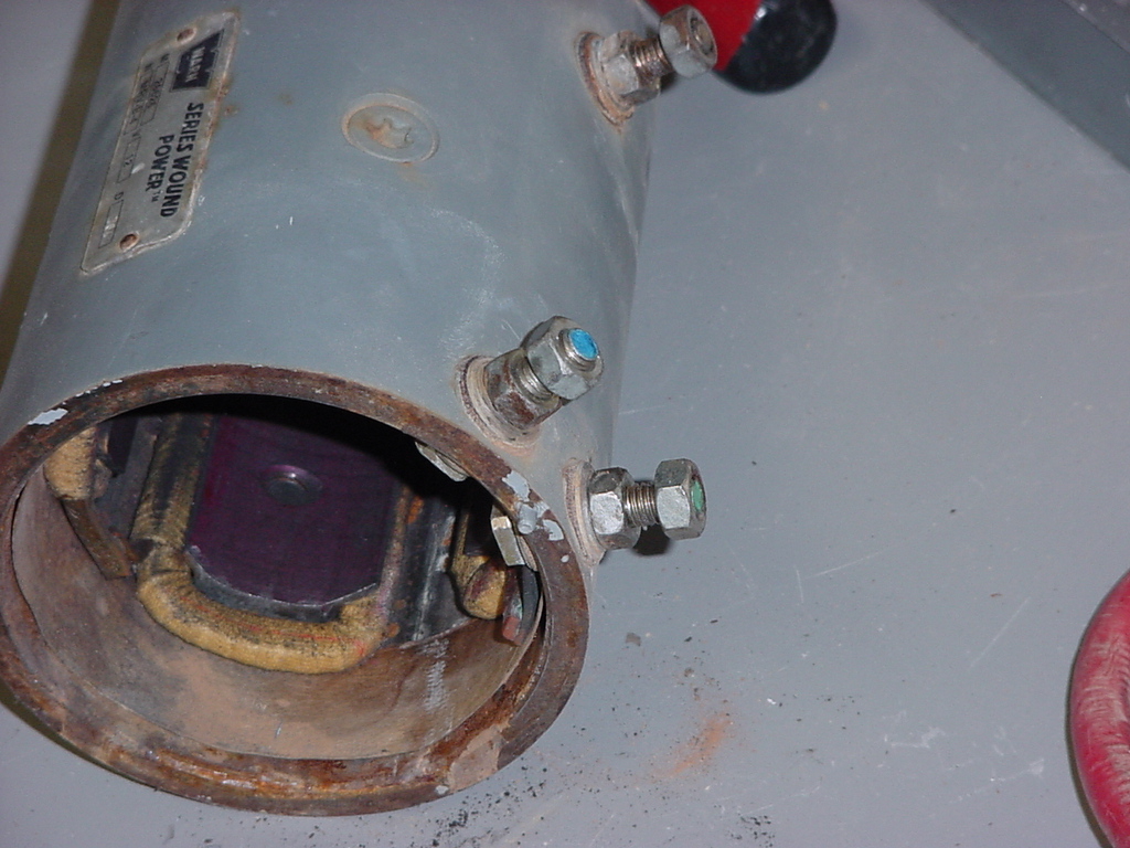
| 5. Mark and remove each cable from it's terminal. The terminals on my motor were embossed, so all I needed to do was mark the wire ends. This is very important, you don't want to cross the wires when reassembling. You will need a 1/2" socket or combo wrench |
 |
 |
 |
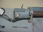 |
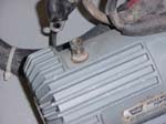
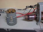
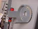
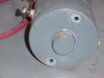
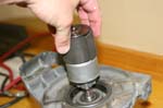
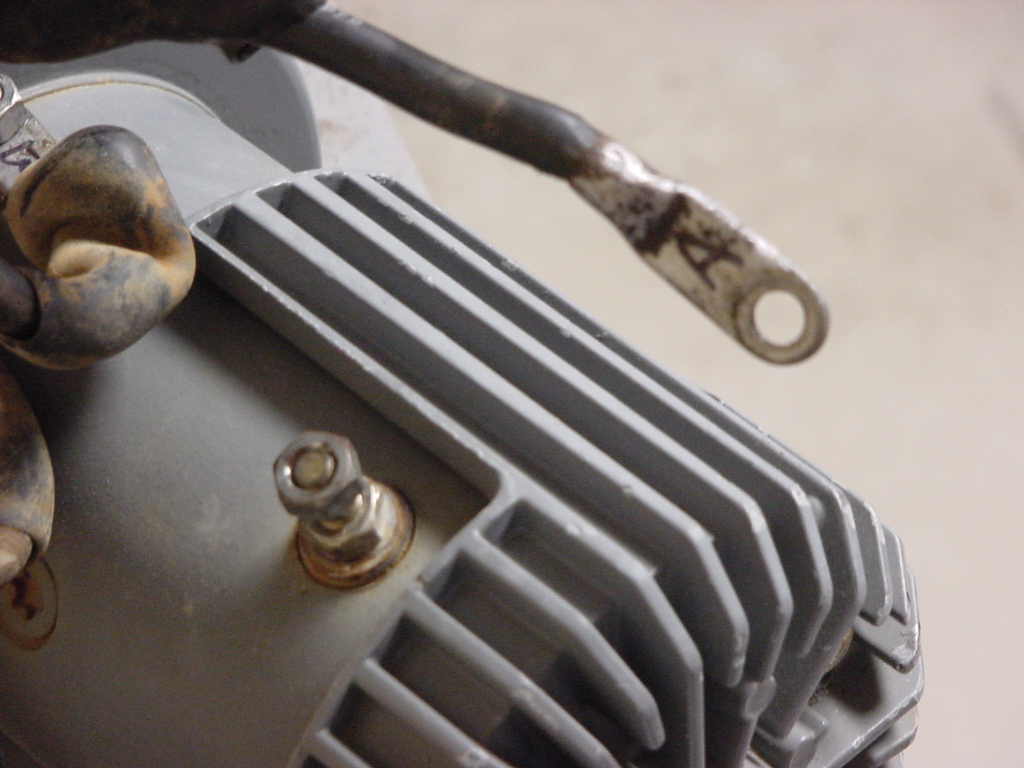
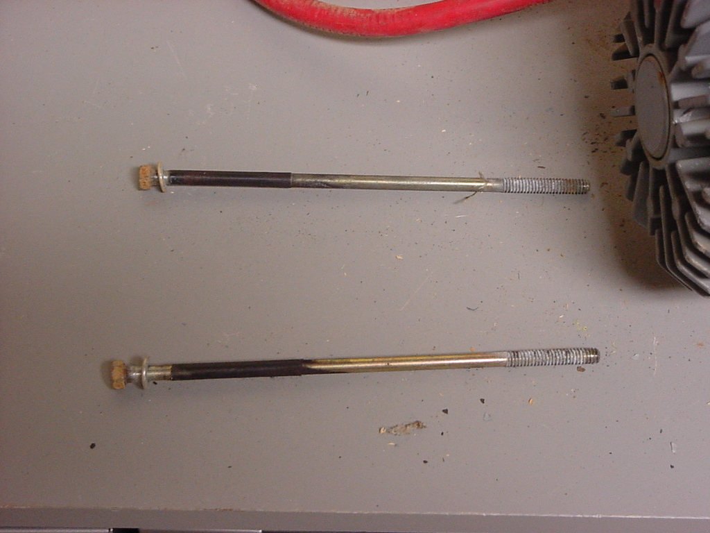
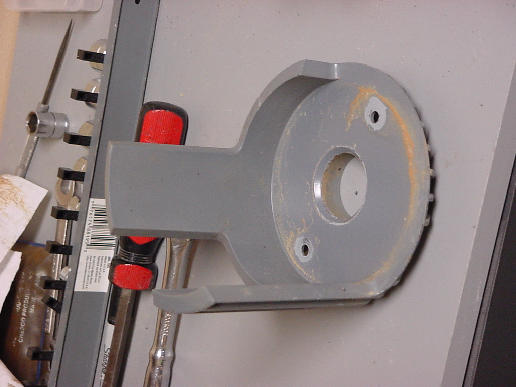
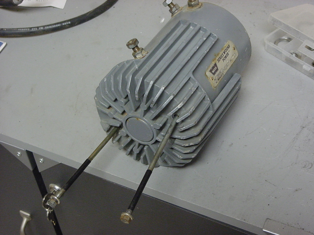
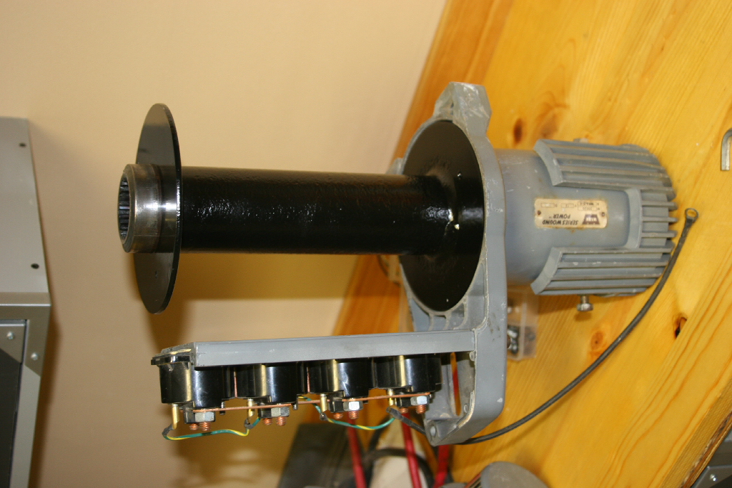
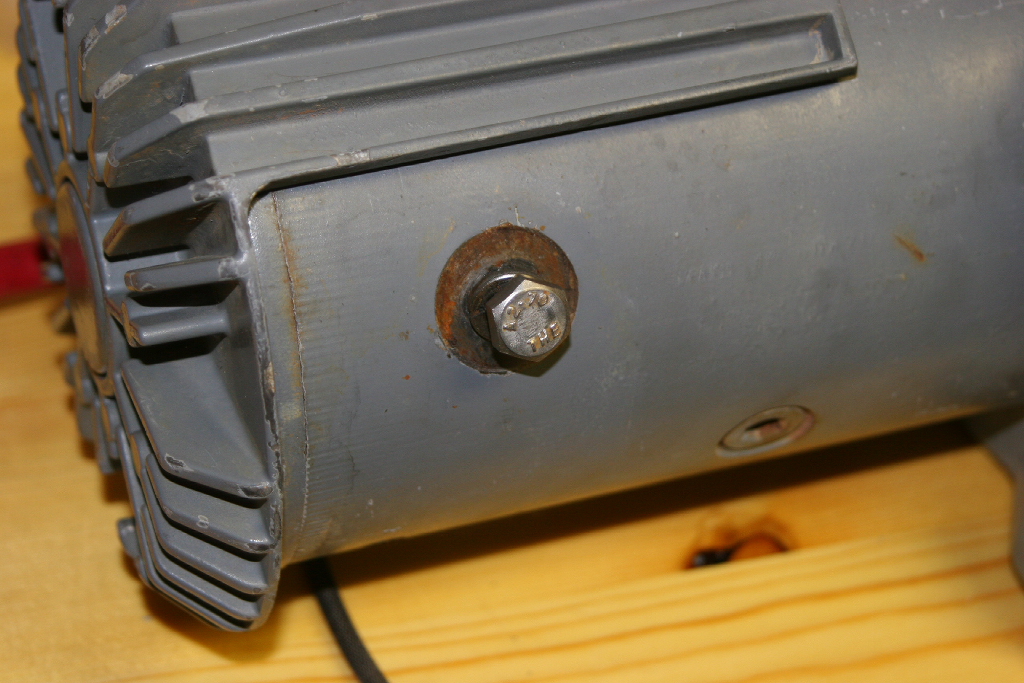
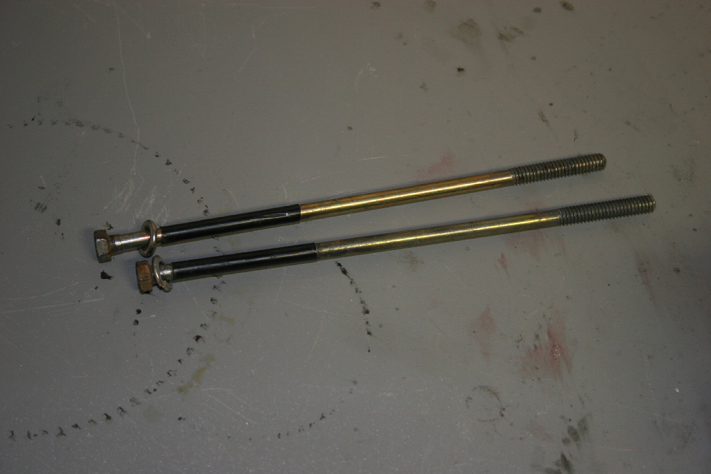
| 6. Remove the two bolts holding the motor to the winch with a 3/8" socket. |
 |
 |
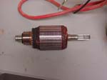
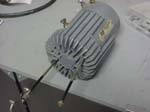
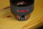
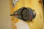
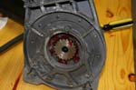
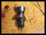
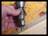
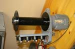
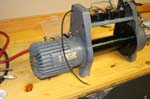
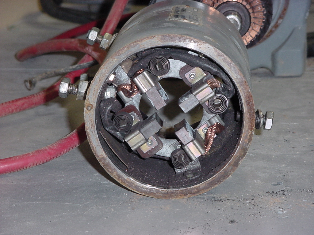
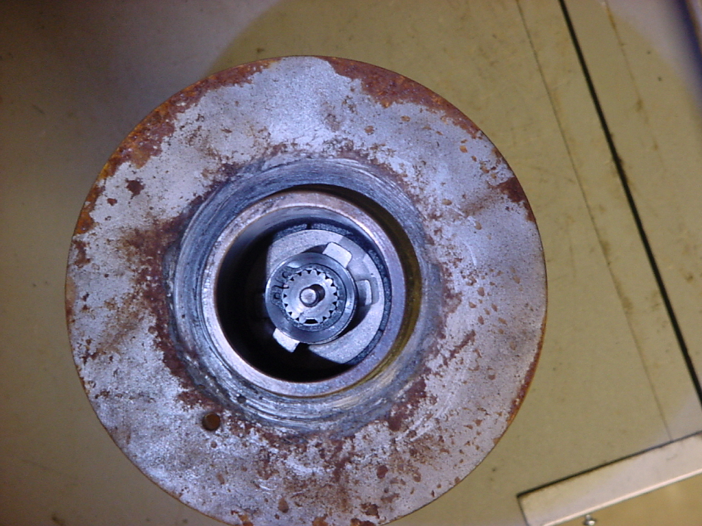
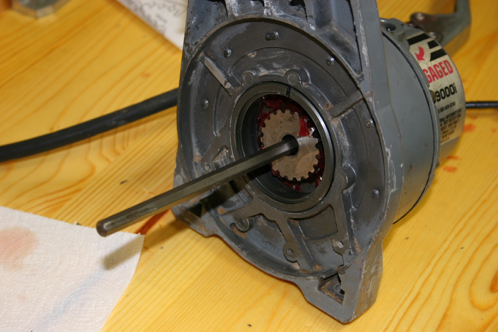
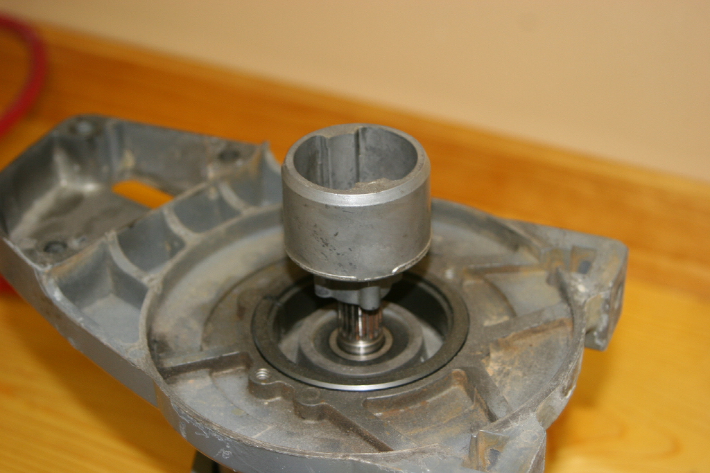
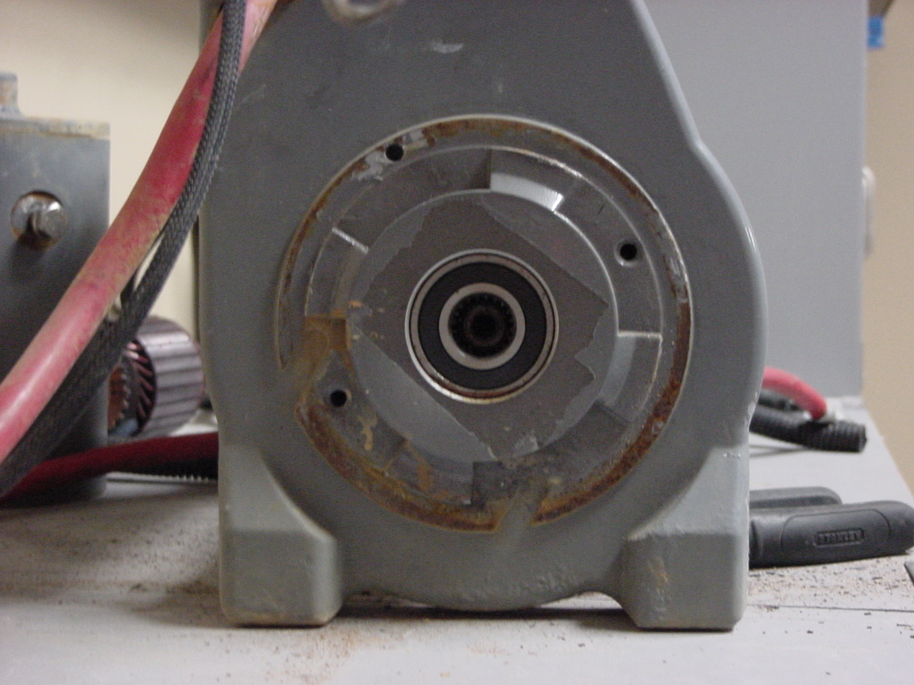
| 7. Remove the motor from the winch. It just pulls out, if it's stuck. lightly wrap on the housing right at the joint with the winch. Hopefully the rotor comes off with the housing, not left in the winch like mine. If it does, just pull the rotor out of the winch and set it aside. I will continue as if the rotor was still in the motor housing. |
 |
 |
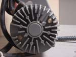
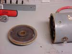
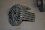
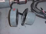
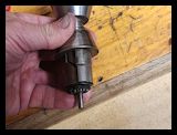
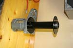
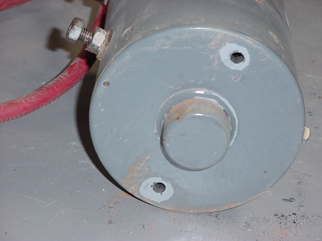
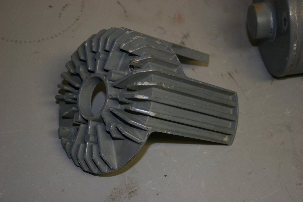
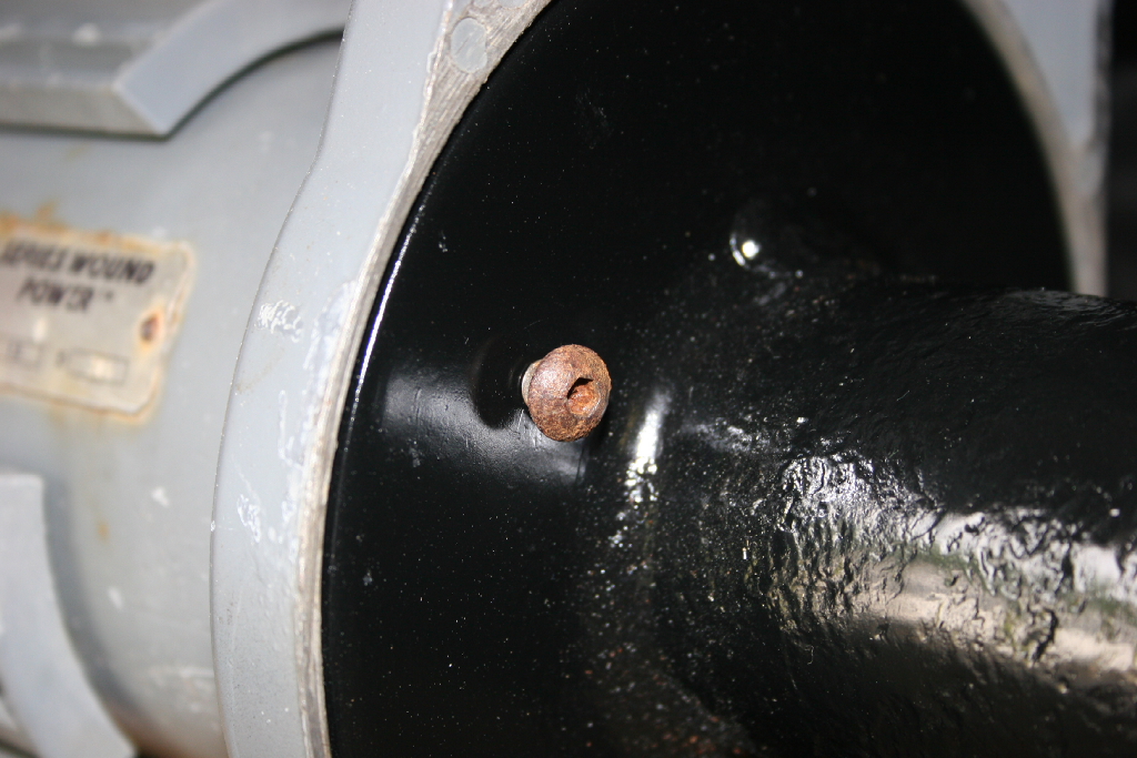
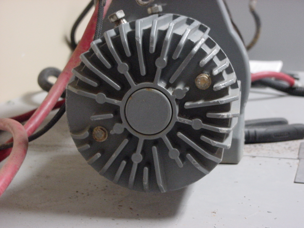
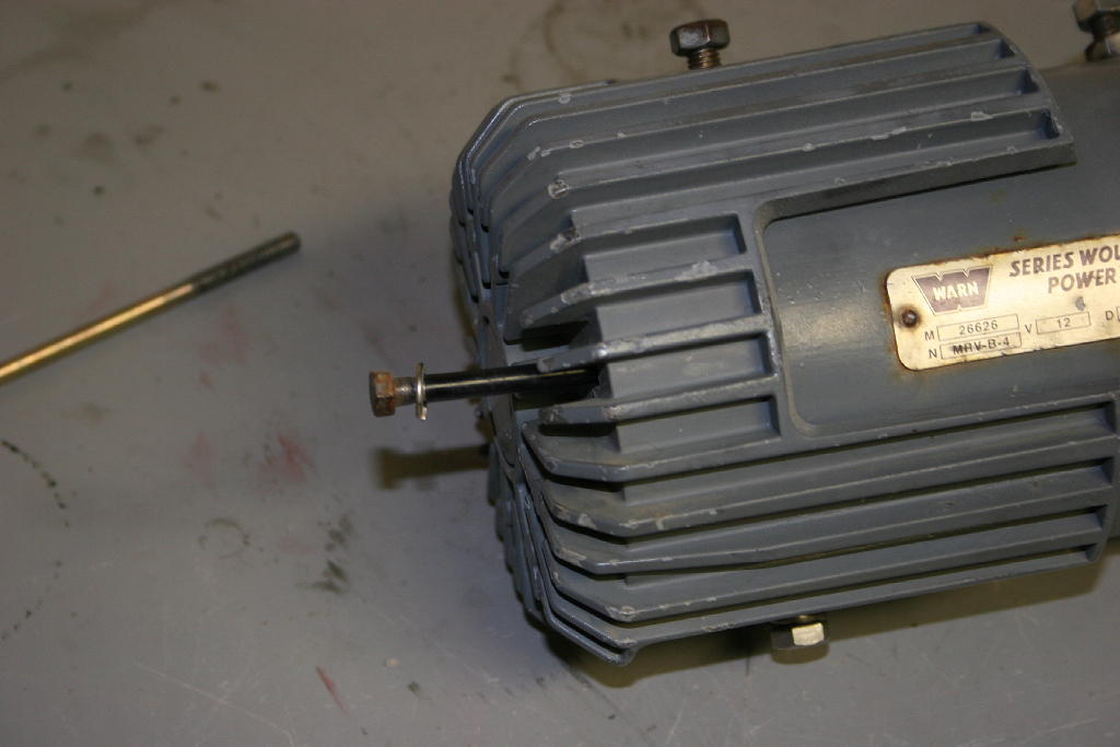
| 8. If your winch has cooling fins, you will need to tap them off. They fit over the beveled button on the end of the motor housing. |
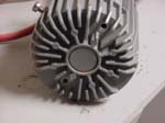 |
 |
 |
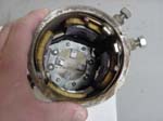
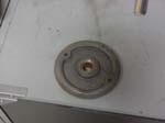
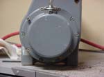
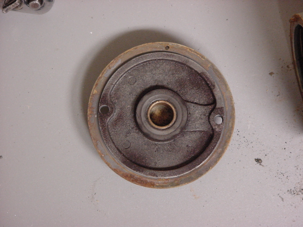
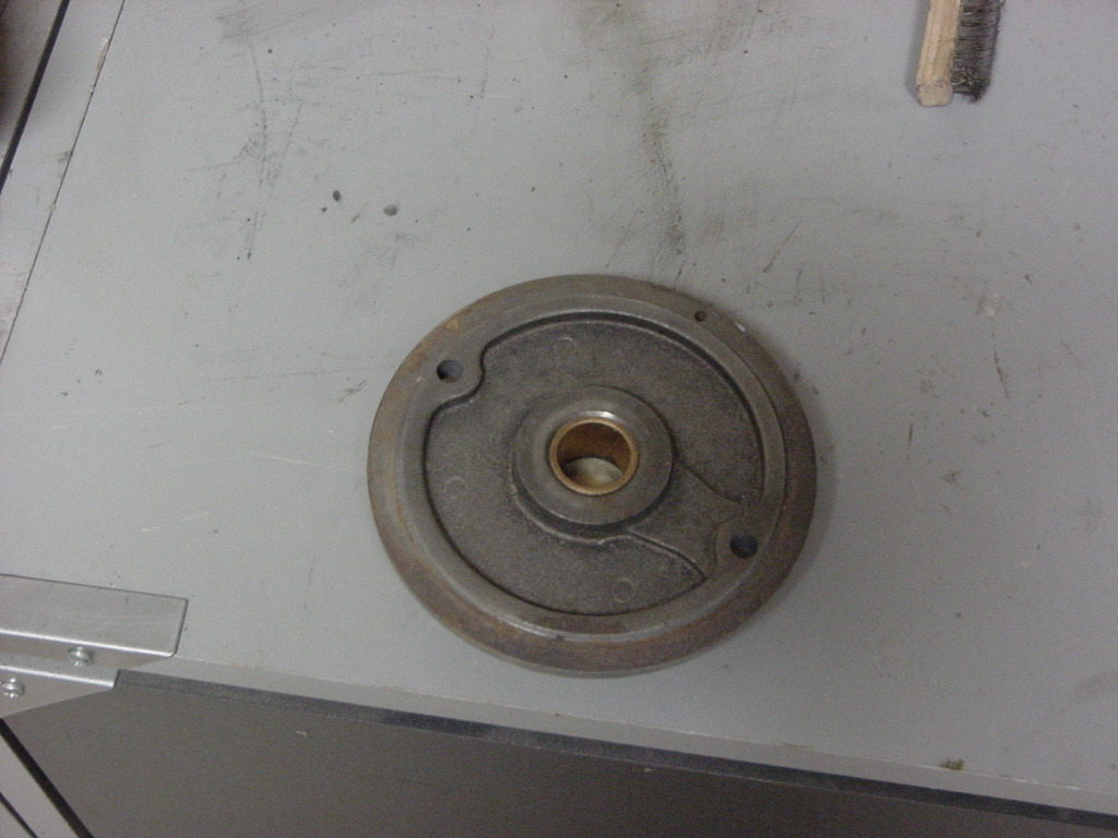
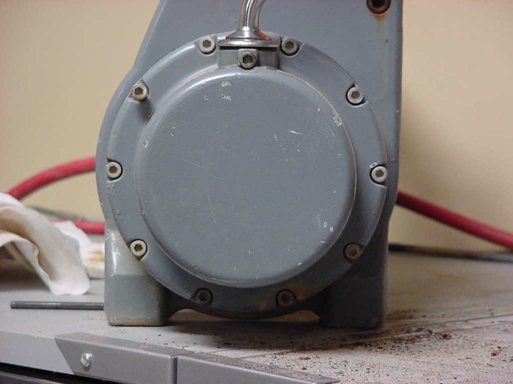
| 9. Remove the end of the motor housing, by lightly tapping at the joint line until the cover comes off. |
 |
 |
 |
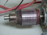
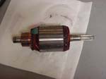
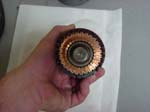
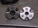
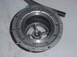
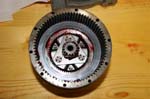
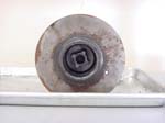
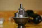
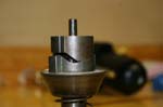
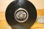
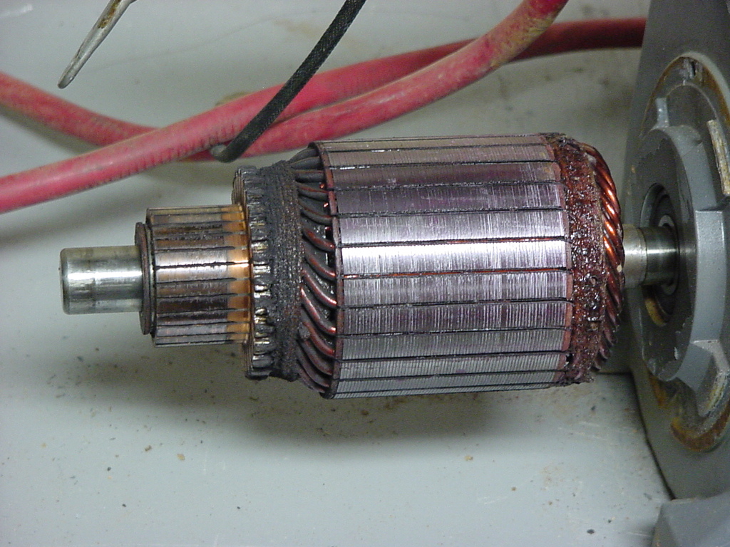
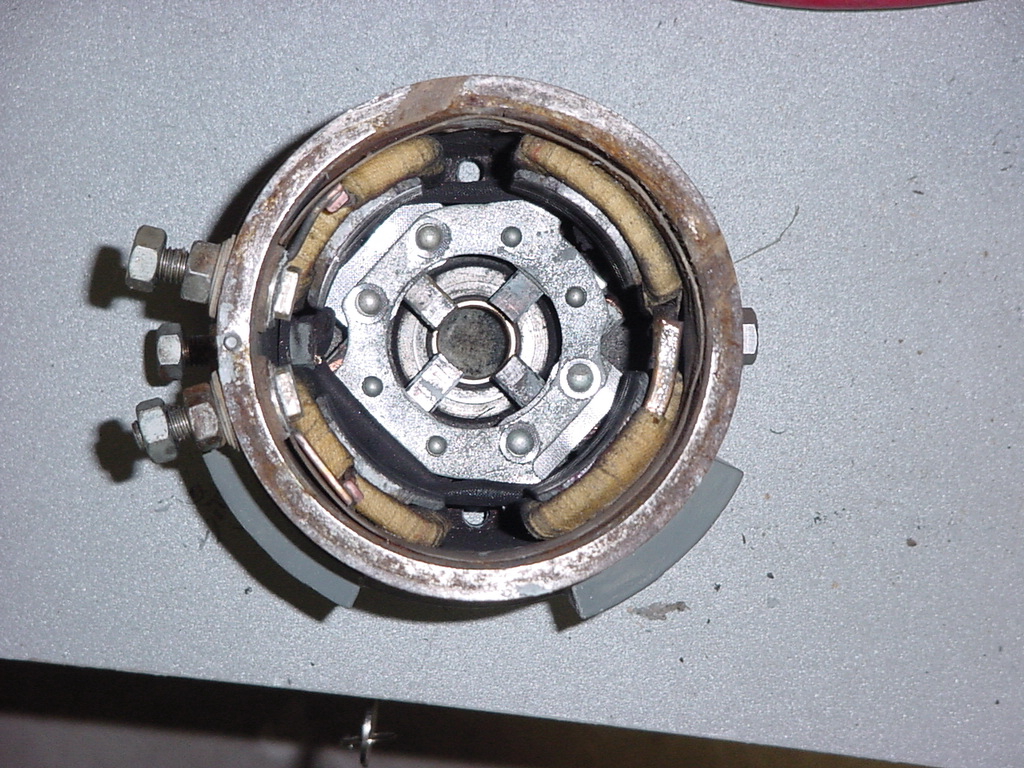
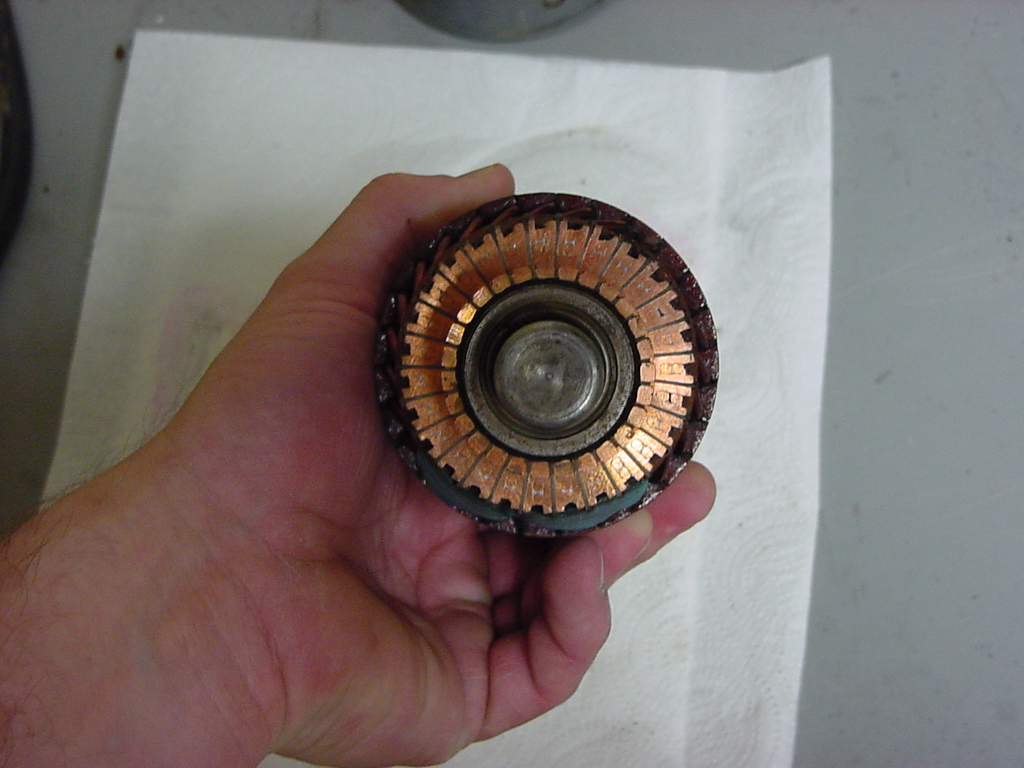
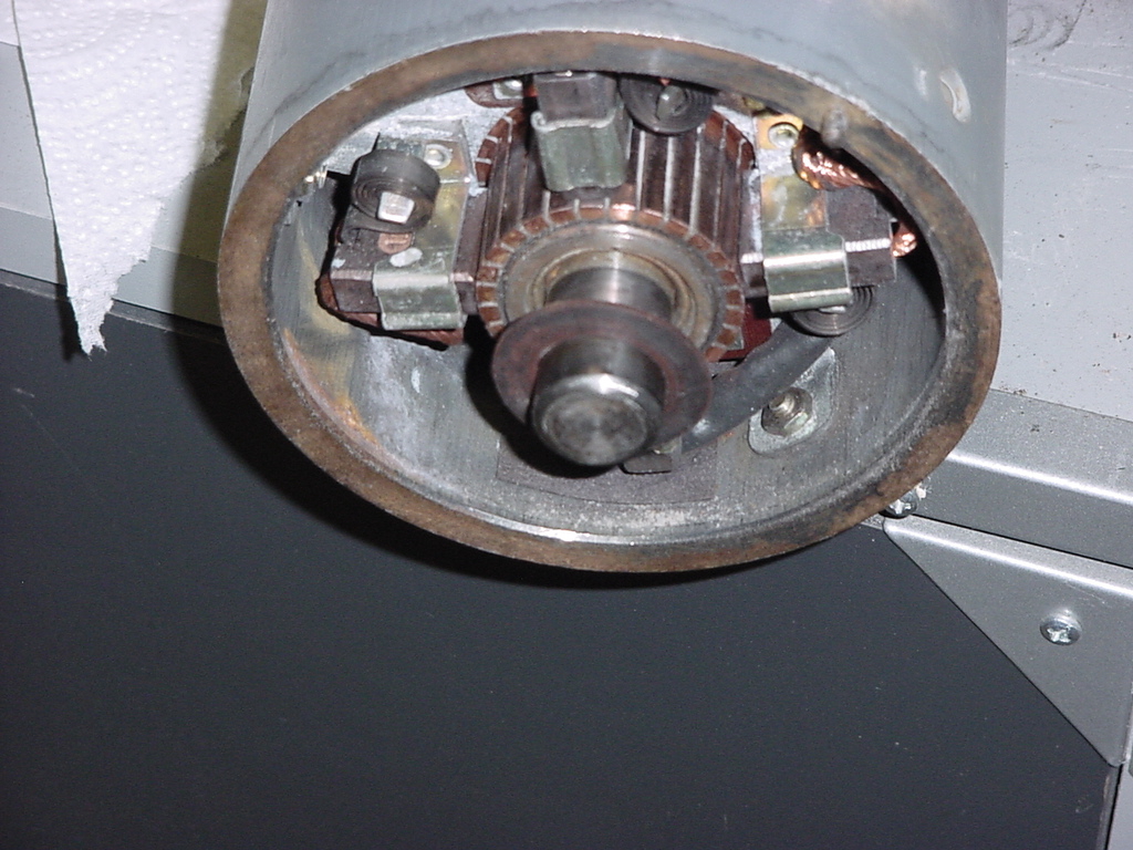
| 10. Now slowly pull the rotor out of the motor housing (if it's still in there). This will give you a good look at how much you have left on your brush's. (Those 4 spring loaded square objects in the center of the picture) |
 |
 |
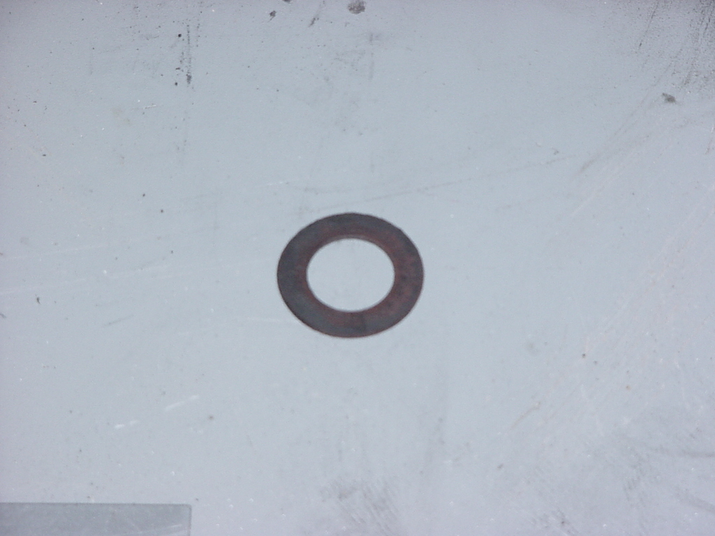
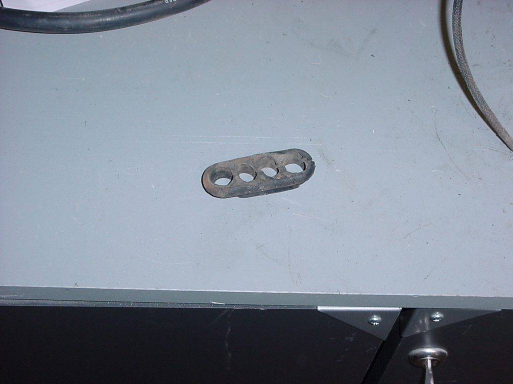
| 11. You may have a felt or cardboard looking washer on the end of the rotor shaft. Carefully remove this and set it aside, you will reinstall it later. |
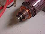 |
 |
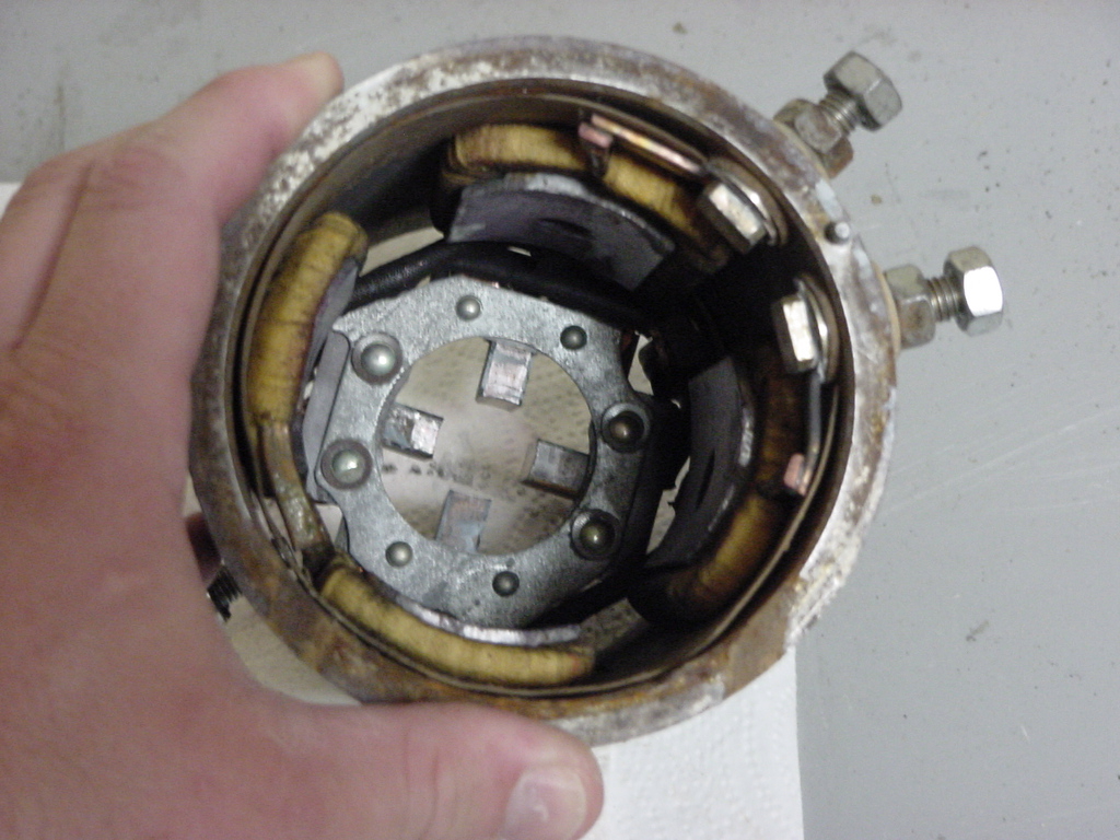
| 12. Inspect everything, looking for any charred, any bright shiny spots (possible damage or rub spot), damaged wires, or contacts inside. Clean everything out. I used a toothbrush and some canned air to blow the dust and debris out of the motor. If you have some electrical cleaner you can wipe down all the contact points, rotor and inside the housing. |
| |
| Reassemble the motor: |
| 1. Slide the rotor back inside the motor housing. The short shafts section goes in first. |
 |
 |
| 2. Make sure nothing is inside the motor housing and slowly slide the rotor inside. Do not drop the rotor into the motor housing, you could snap off the brush's at the end of the housing. |
 |
 |
| 3. Hold steady pressure on the rotor, and using a small wood dowel, or similar wood object slowly push each brush back into it's housing. The brush will catch on the side of the rotor. Once all 4 are pushed out you can finish inserting the rotor in the housing. |
 |
| 4. Install the washer on the end of the rotor. |
 |
 |
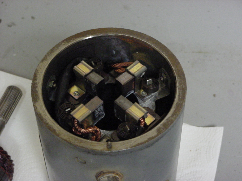
| 5. Line up the hole in the edge of the cover with the alignment pin on the motor housing and install the cover. |
 |
 |
| 6. If you had cooling vanes, reinstall the vanes over the end of the motor housing. |
 |
 |
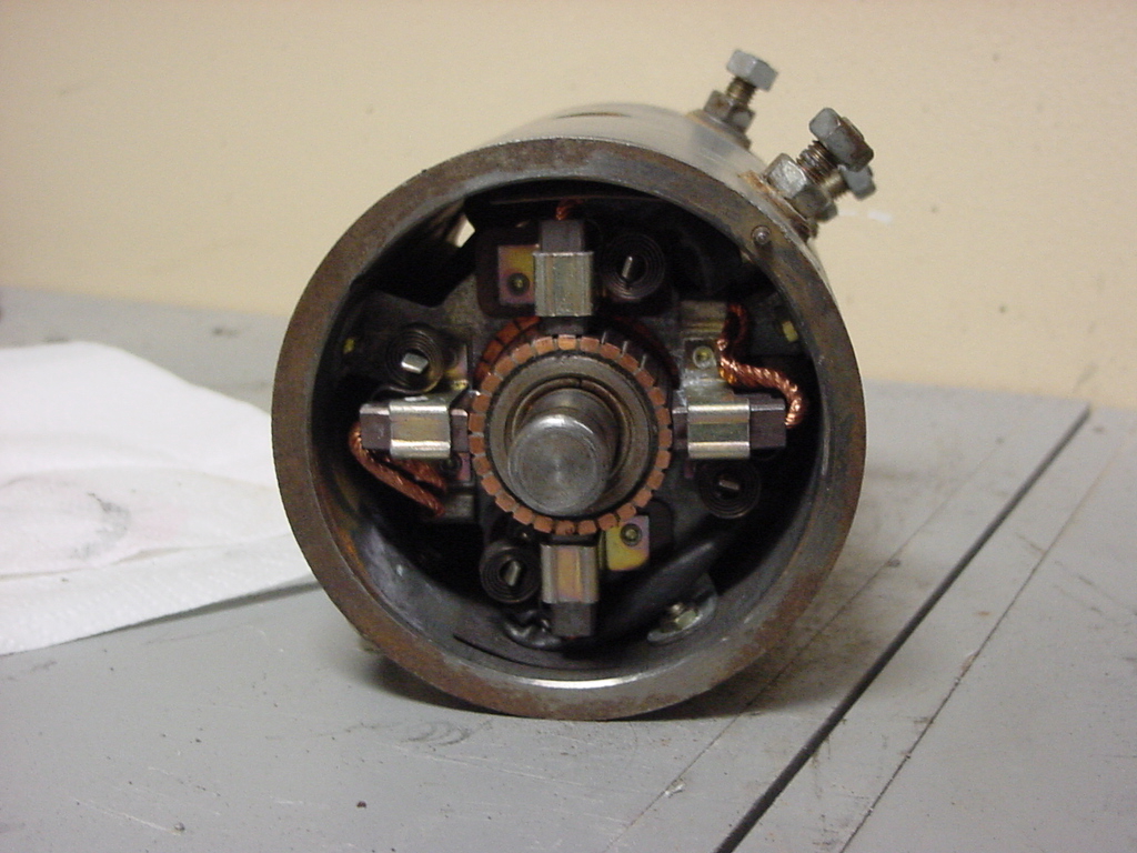
| 7. Insert the two motor bolts so that you don't lose them, and set the motor off to the side somewhere safe. |
 |
 |
| |
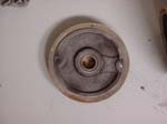
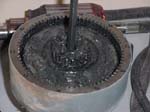
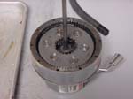
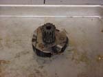
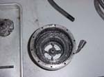
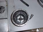
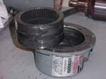
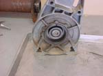
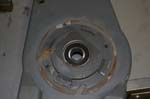
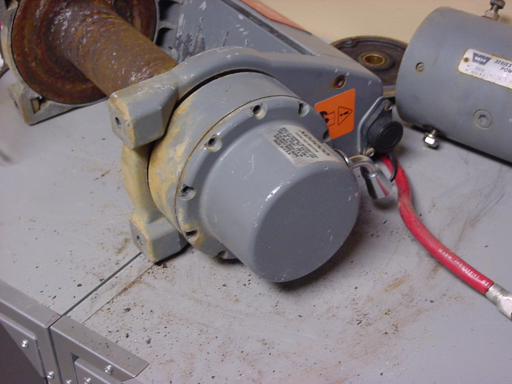
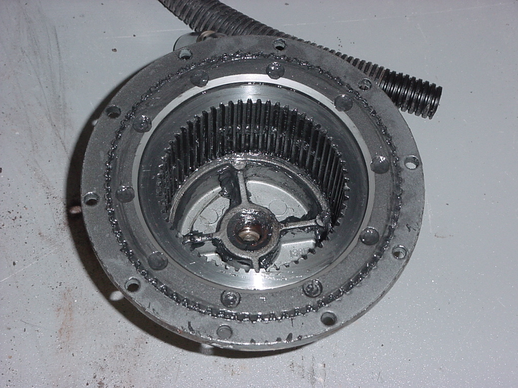
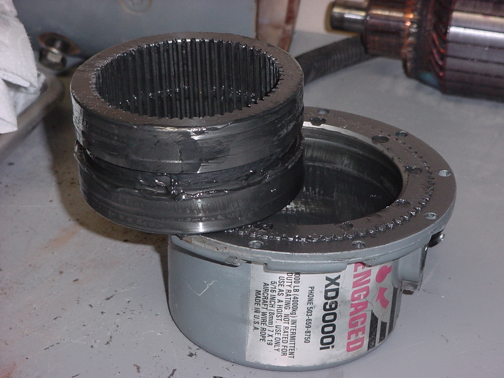
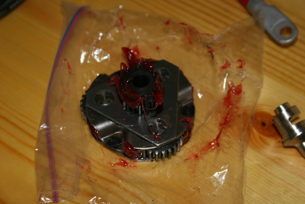
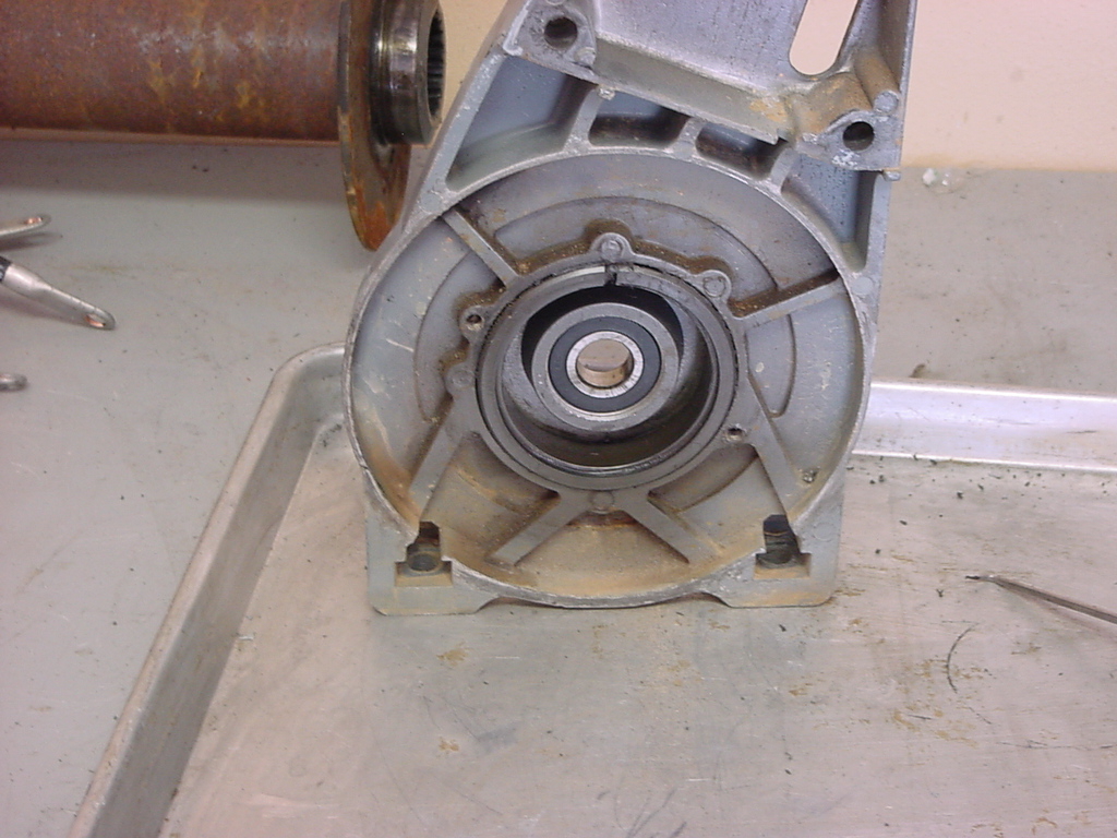
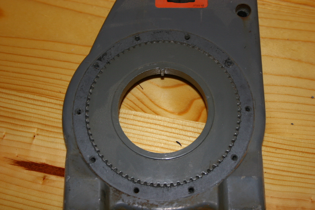
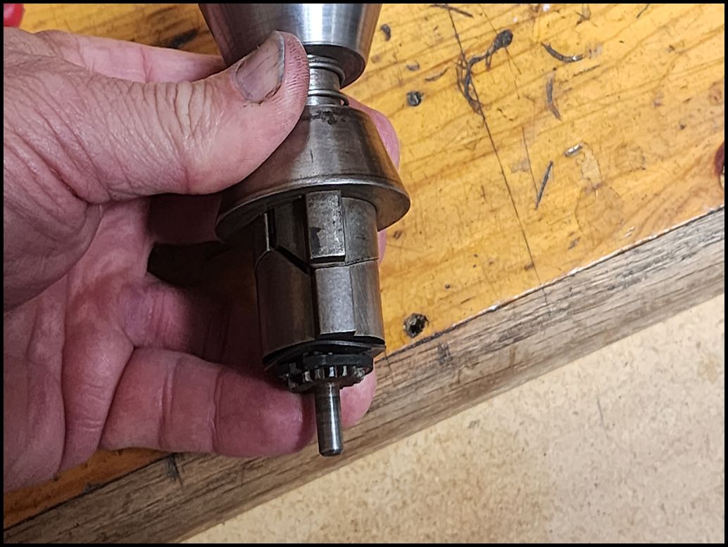
| Planetary gear disassembly: |
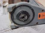
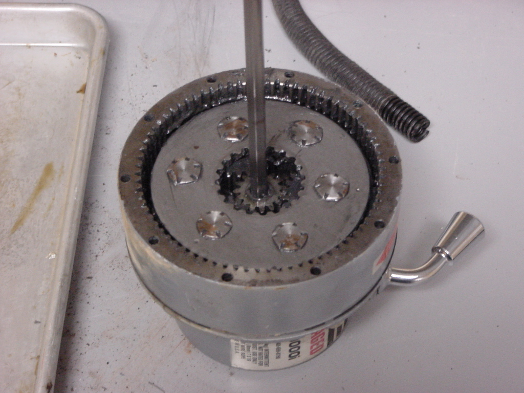
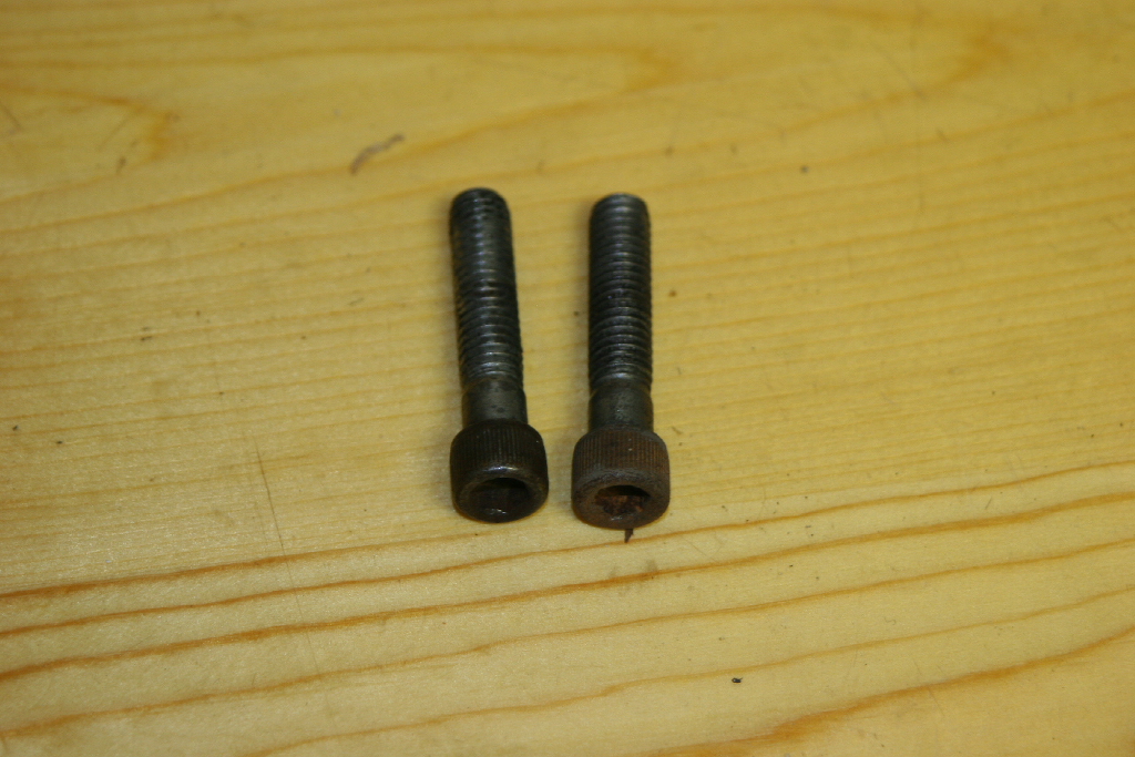
| 1. Remove the ten (10) allen head screws from the end housing of the planetary gear assembly with a 5/32 " allen wrench. |
 |
 |
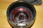
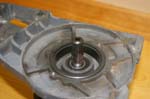
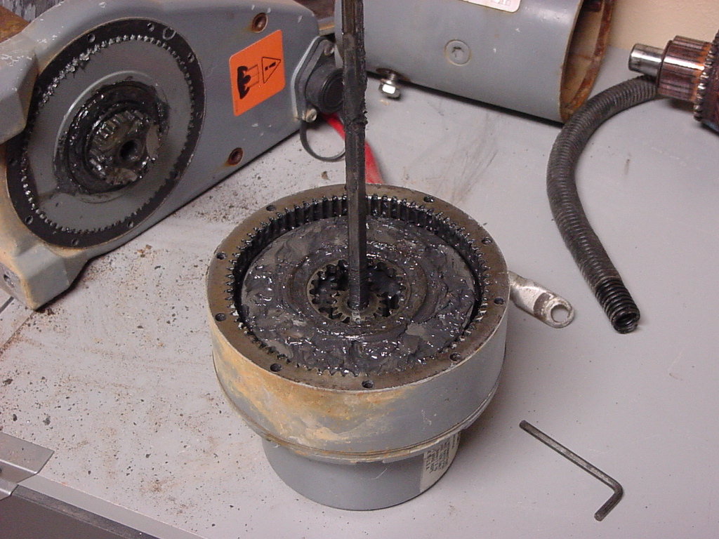
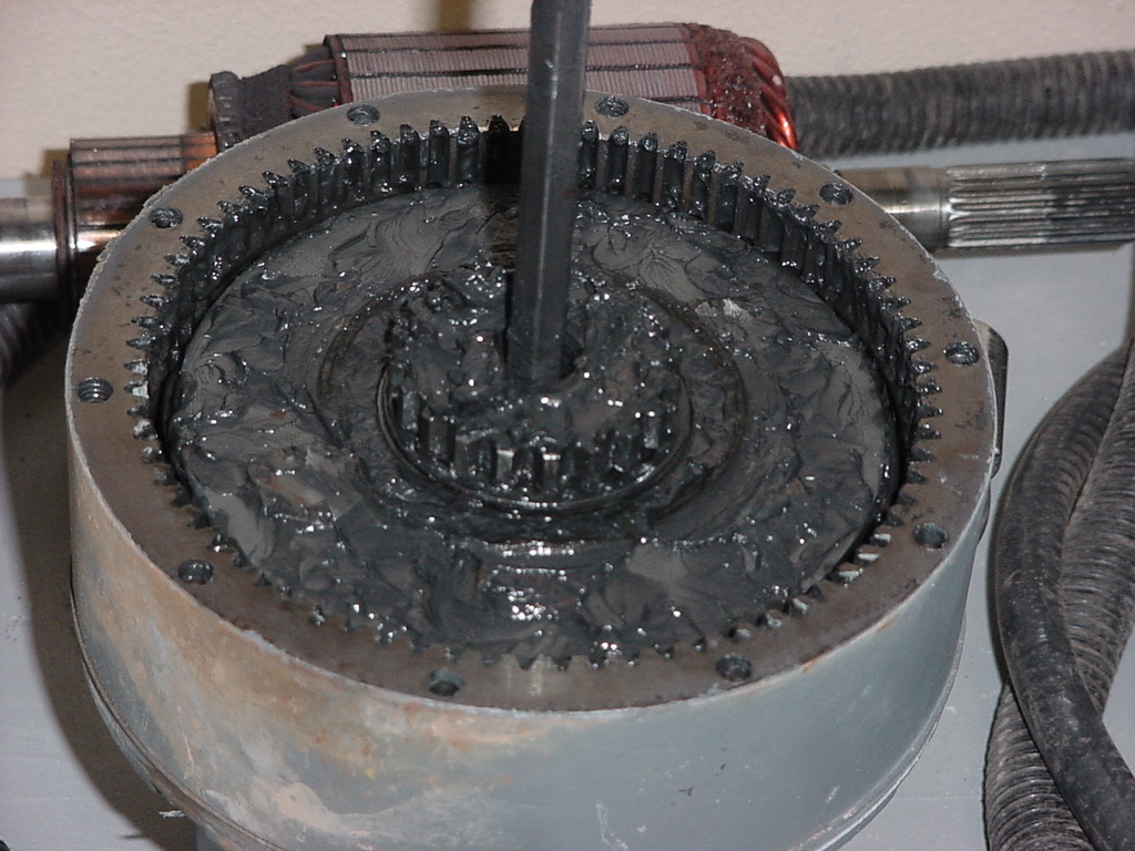
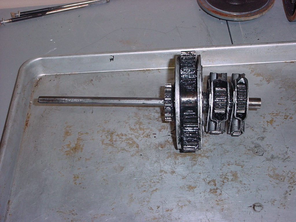
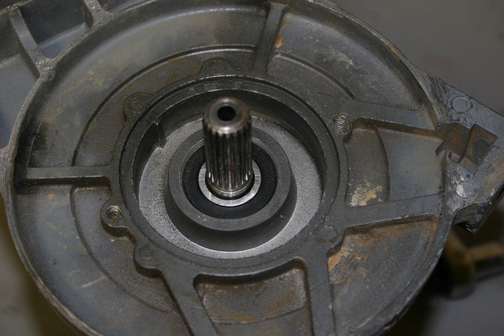
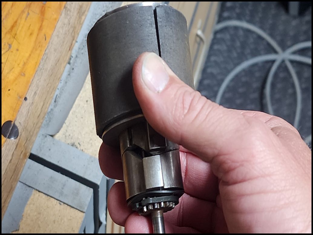
| 2. Remove the planetary gear assembly from the winch by lightly tapping on the housing and pulling it straight off. There will be a long center shaft that you will need to pull all the way out. |
 |
 |
| 3. Stand the assembly on end so that nothing falls out of it. |
 |
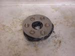
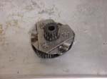
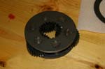
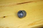
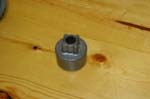
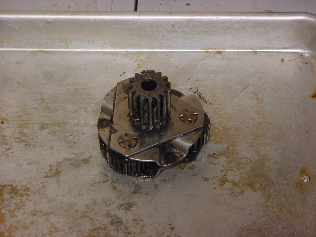
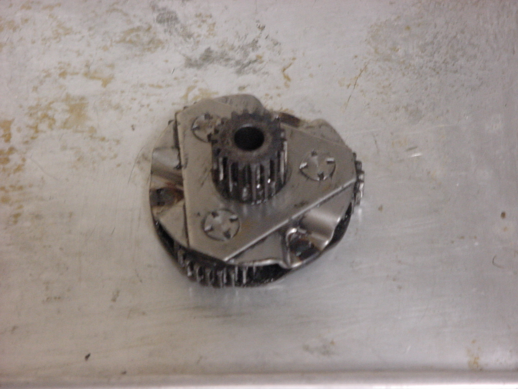
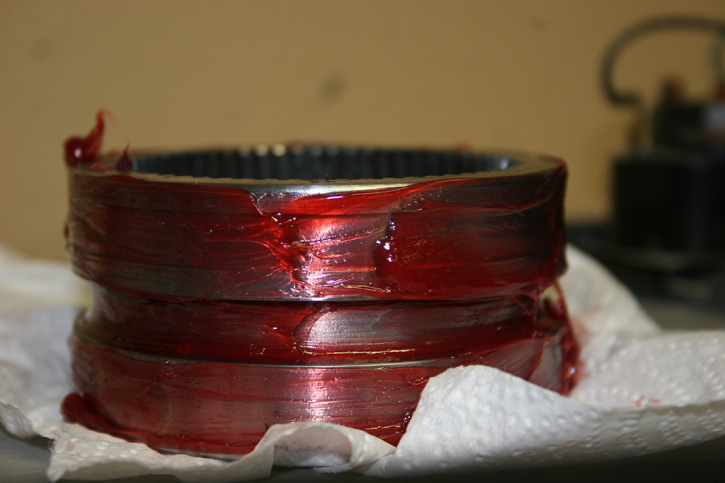
| 4. The drive spline may remain in the winch drum. Just pull it off. |
 |
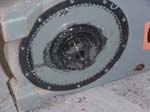 |
 |
| This is how it should have looked coming off. |
 |
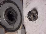
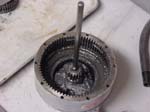
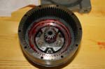
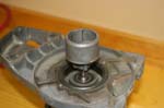
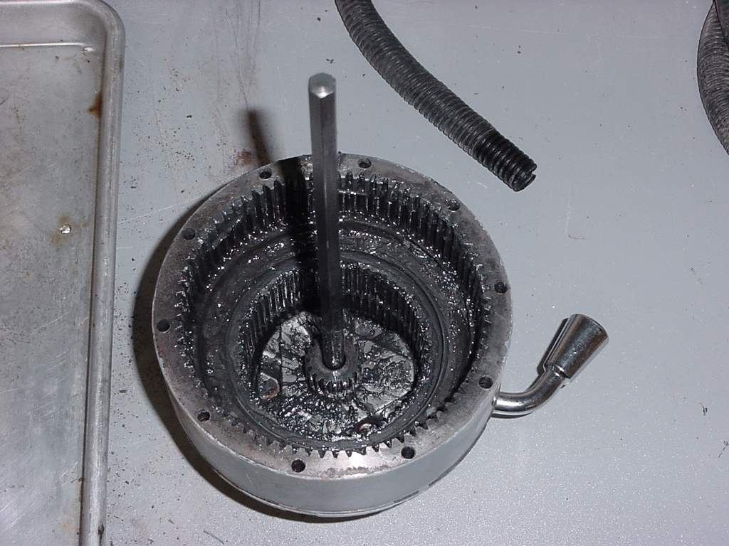
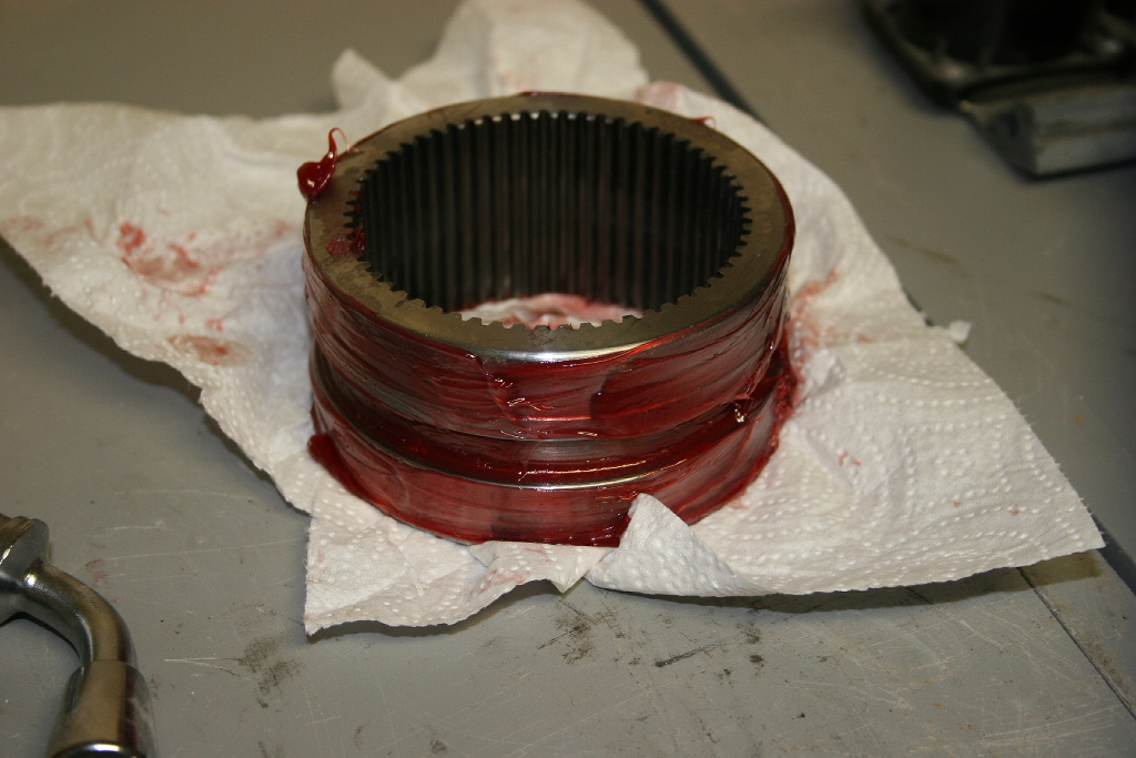
| 5. Remove the drive spline and wipe off the grease. I used some degreaser to clean out all the old grease on the drive gear. Do not spray degreaser into the housing with the parts in there, you will make them even harder to remove if you do. You may be able to remove the hex shaft at this point. Mine was stuck, so is still visible in these pictures. |
 |
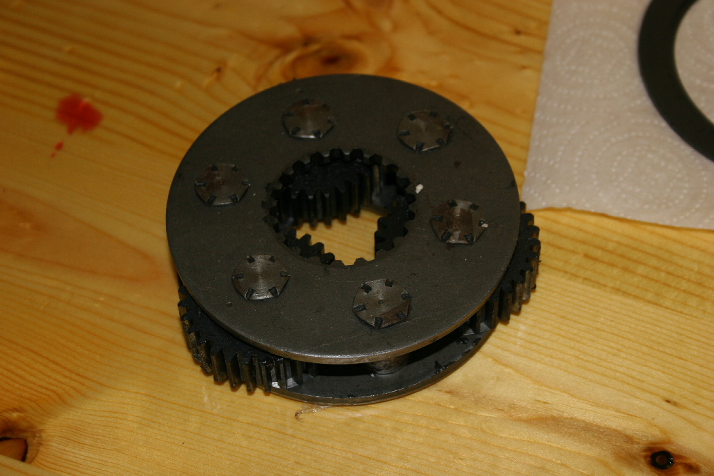
| 6. Remove the Stage 3 carrier assembly, wipe off the grease and clean. |
 |
| 7. Remove the Stage 2 carrier assembly, wipe off the grease and clean. |
 |
 |
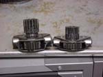
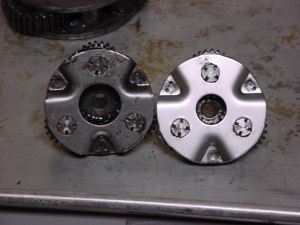
| 8. Remove the Stage 1 carrier assembly, wipe off the grease and clean. |
 |
 |
| Don't worry about mixing up the Stage 1 and 2 carrier assemblies. They are different sizes and one fits inside the other. |
 |
 |
| 9. Remove the hex shaft if you haven't already. Wipe off the grease and clean. |
 |
 |
| I stuck all the pieces together at this point just so I didn't forget how they went together. Not really necessary, but it did keep the parts in one location. |
 |
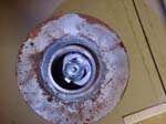
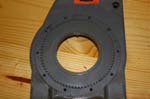
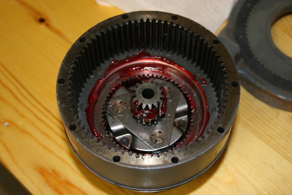
| 10. Remove the small sun gear from the bottom of the planetary gear assembly end housing. Wipe off the grease and clean. This part was not labeled in the diagram that matched my serial number, but was listed in the parts list. |
 |
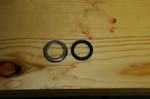
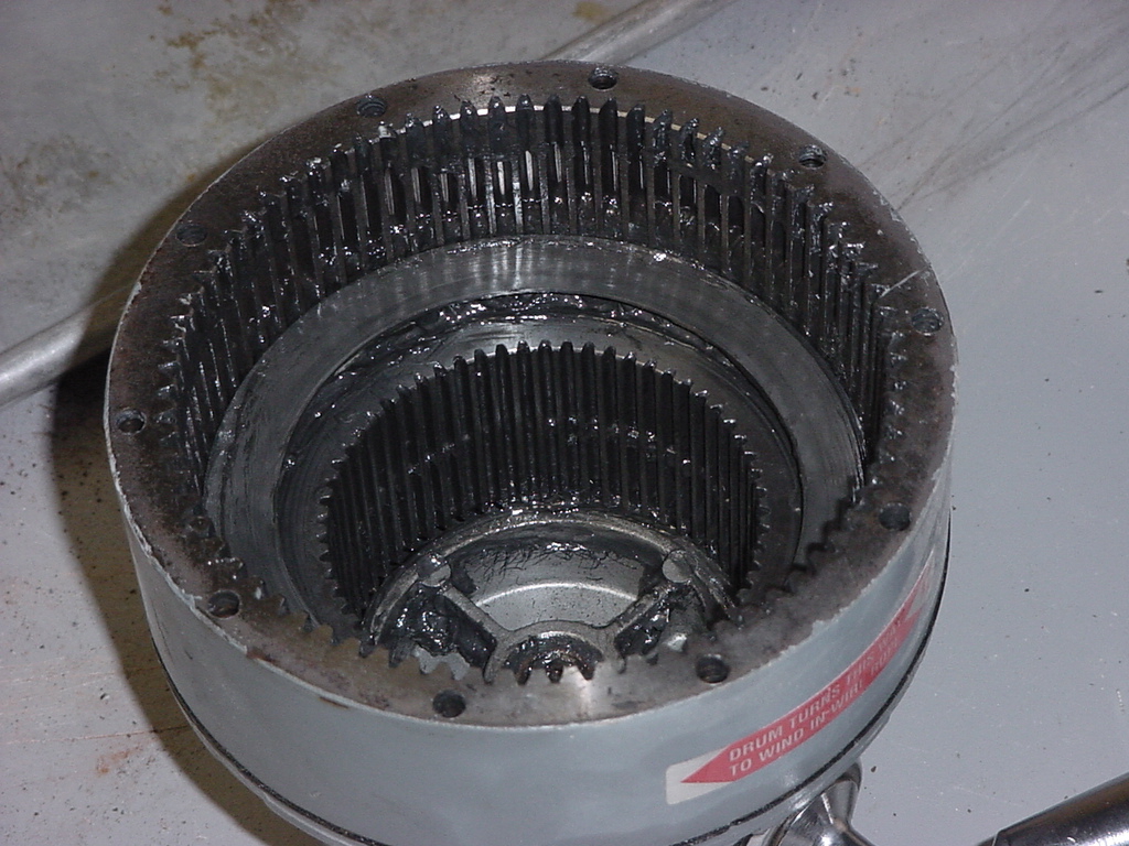
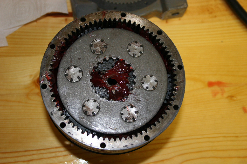
| 11. Wipe off the grease from inside the housing. You will expose a plastic thrust bearing. Note the way that the bearing is installed. |
 |
 |
| One side of the thrust bearing has a grove in it. This grove goes down when you reassemble it. |
 |
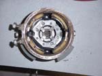
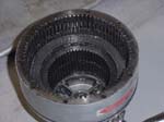
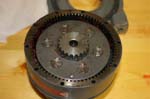
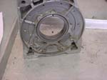
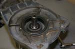
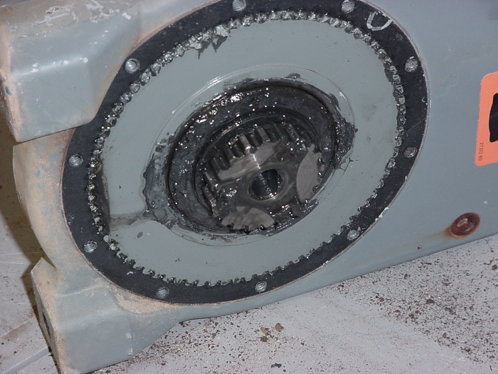
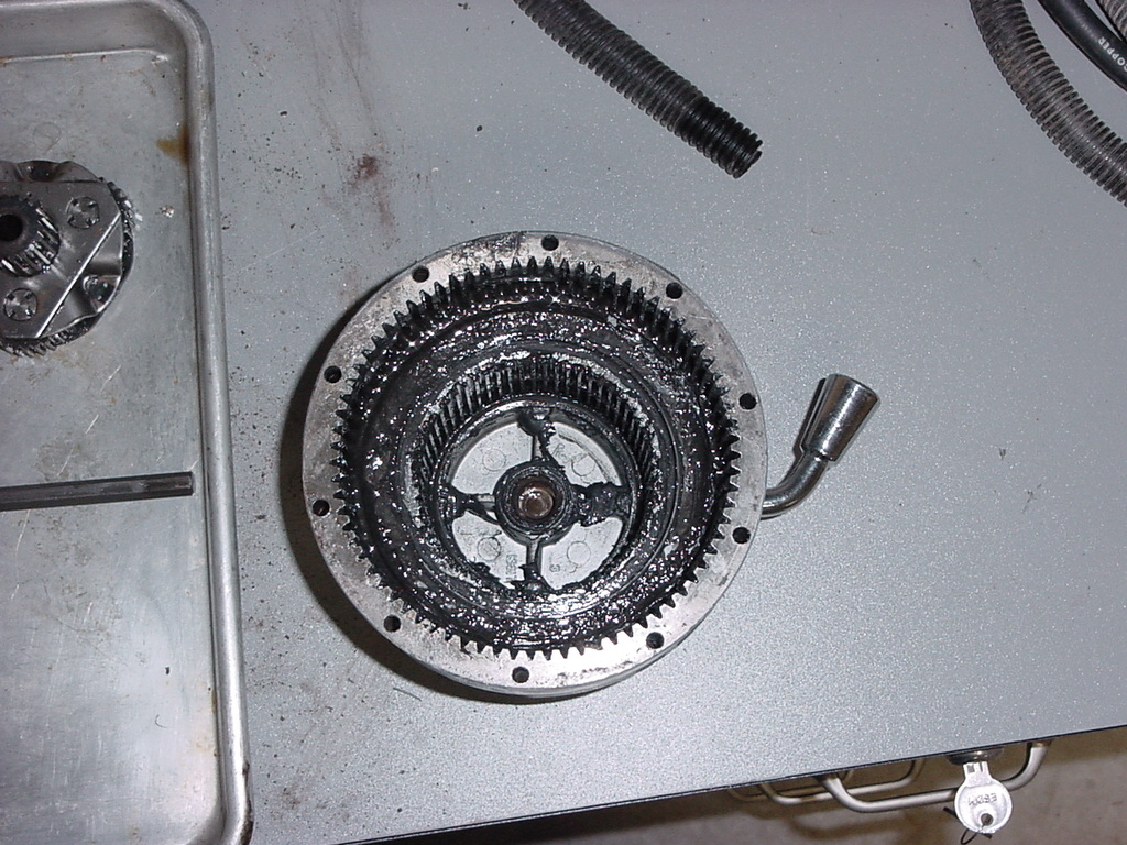
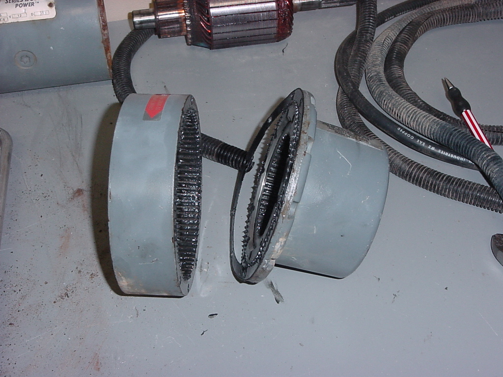
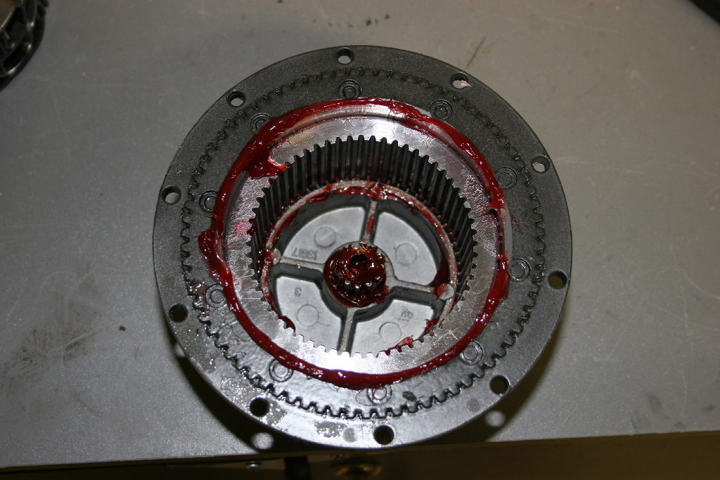
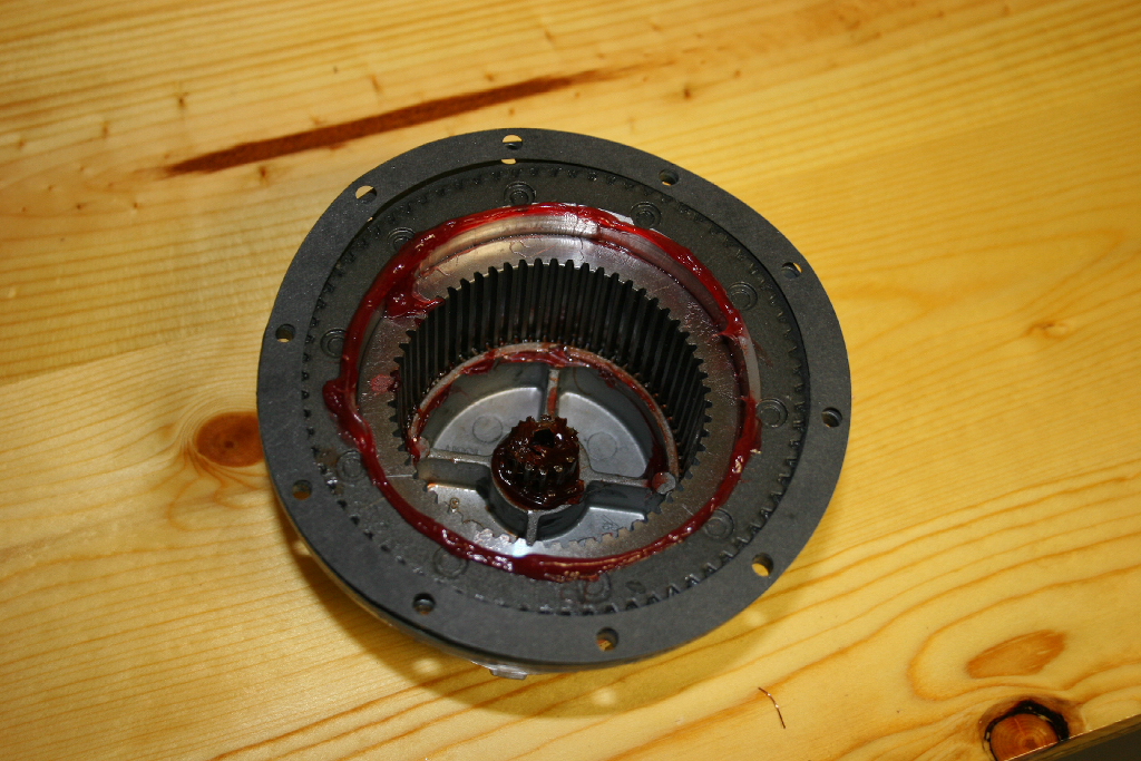
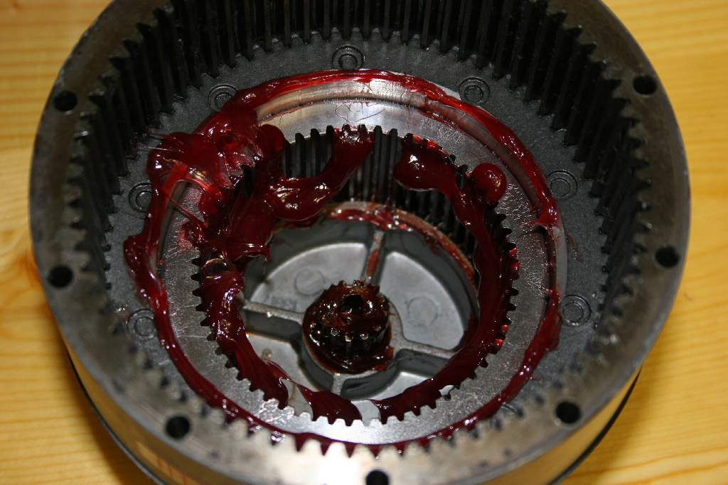
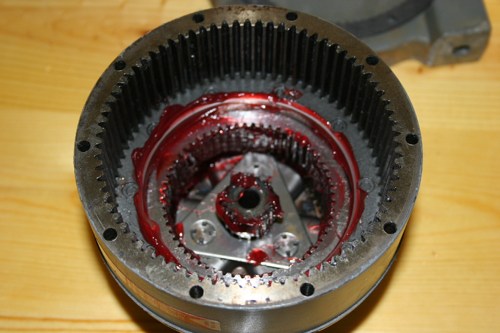
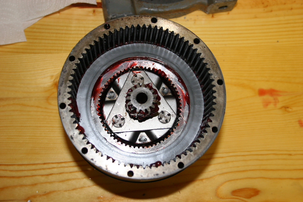
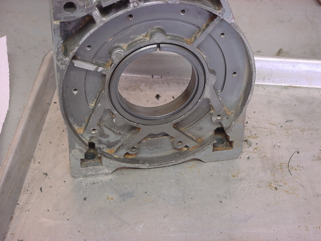
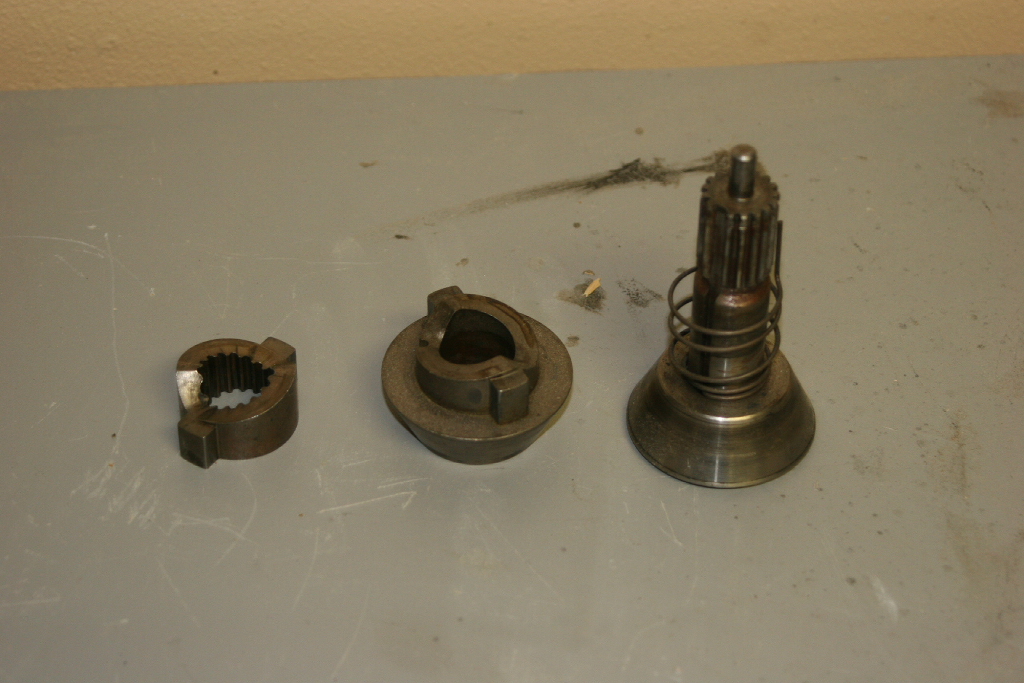
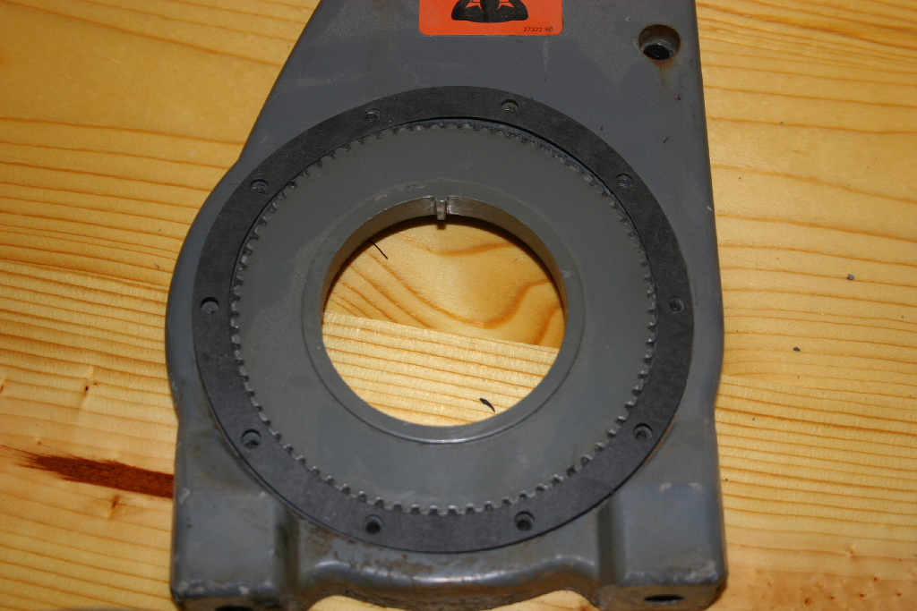
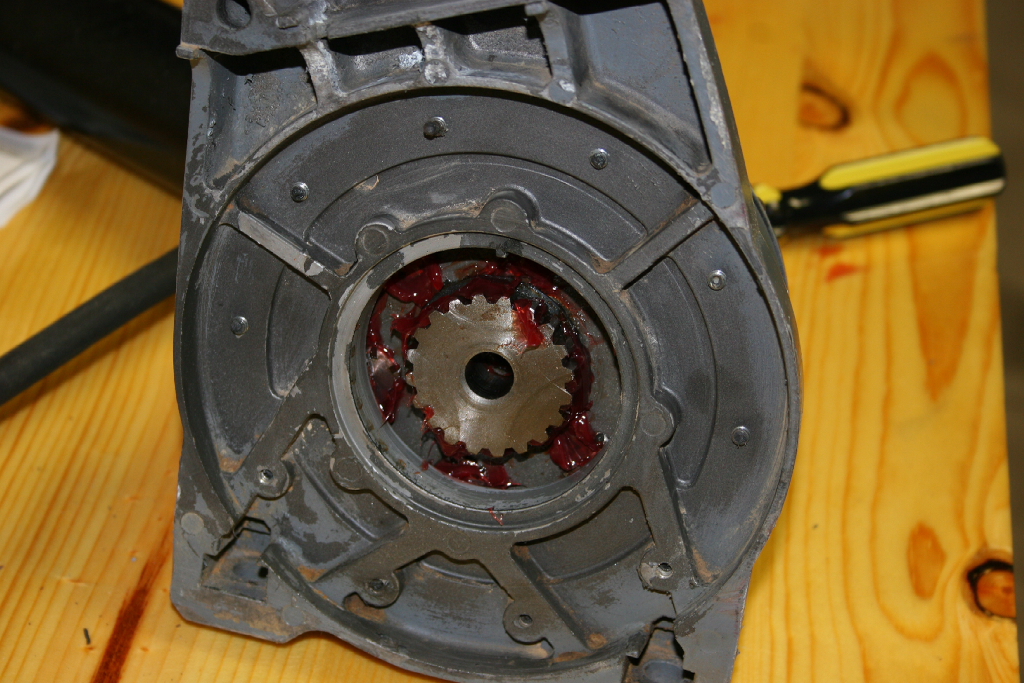
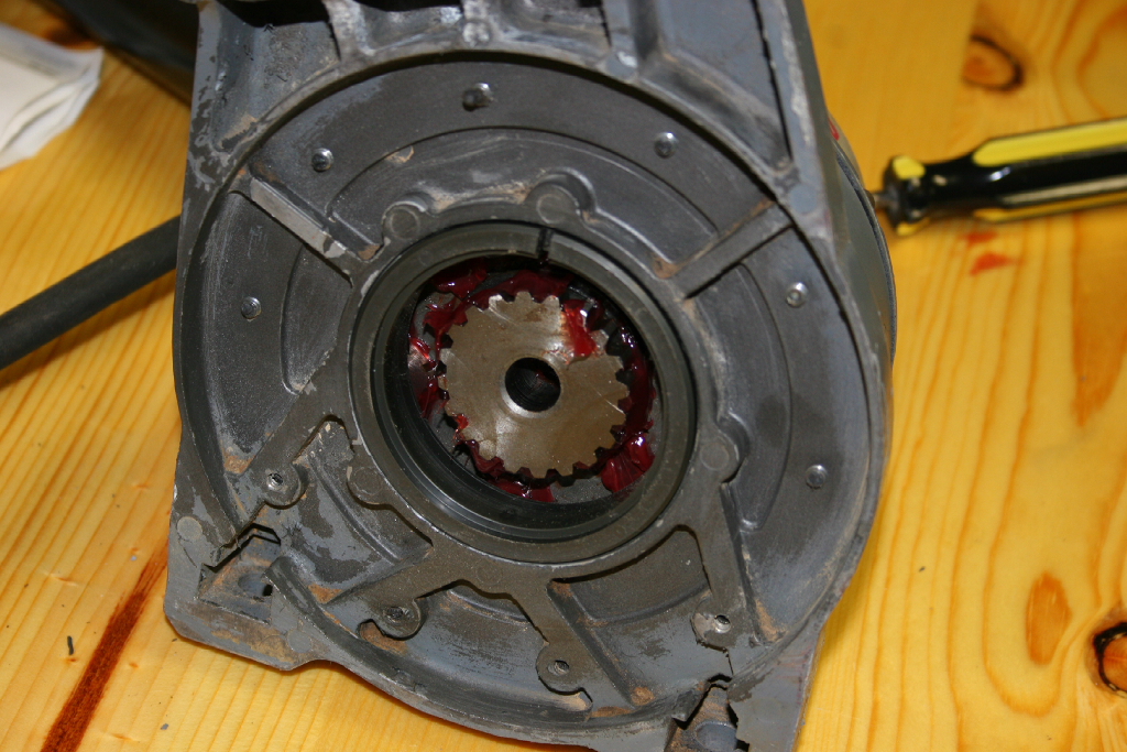
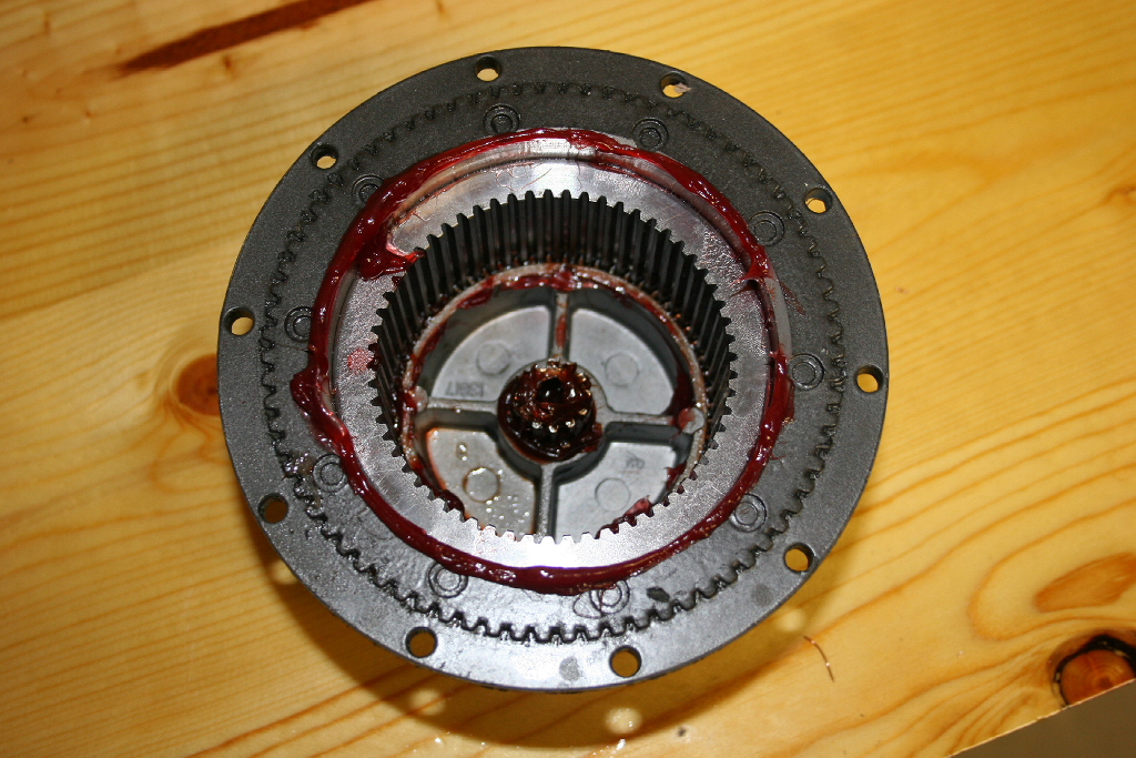
| 12. Seperate the two halves (ring gear and end housing) by lightly tapping at the joining line until they seperate. |
 |
 |
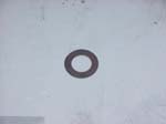
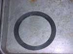
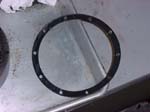
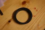
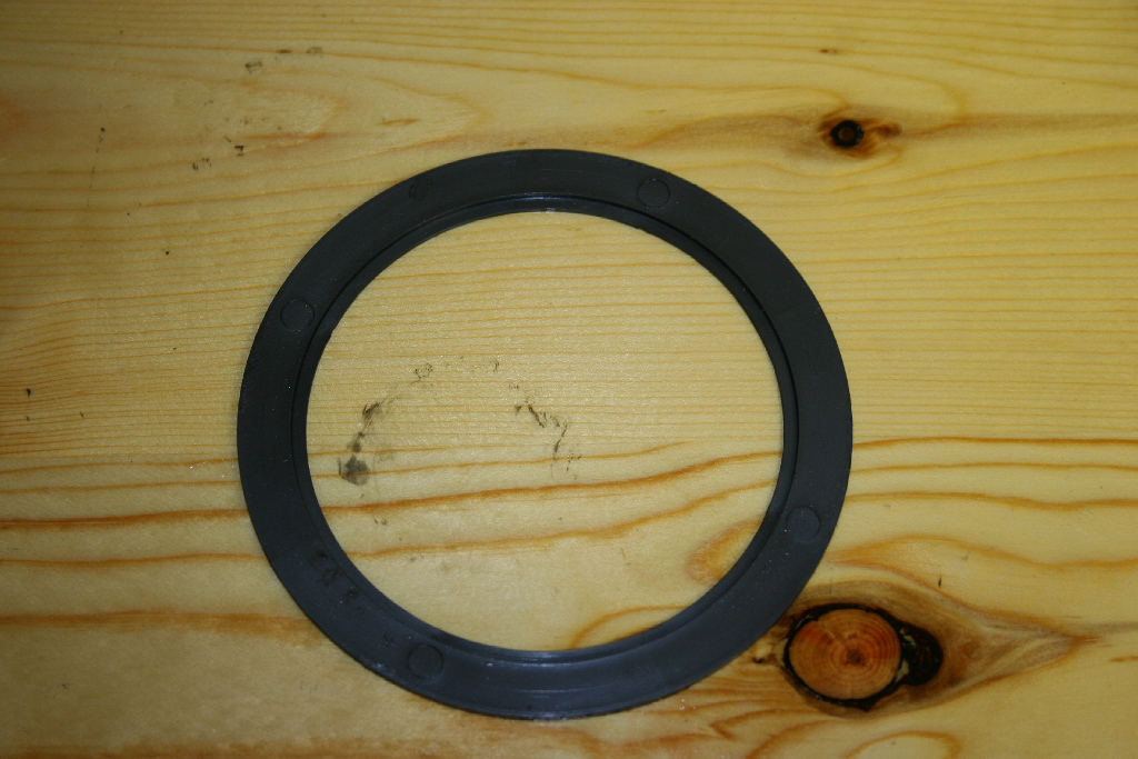
| 13. Remove the old gasket from between these two halves. |
 |
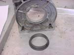
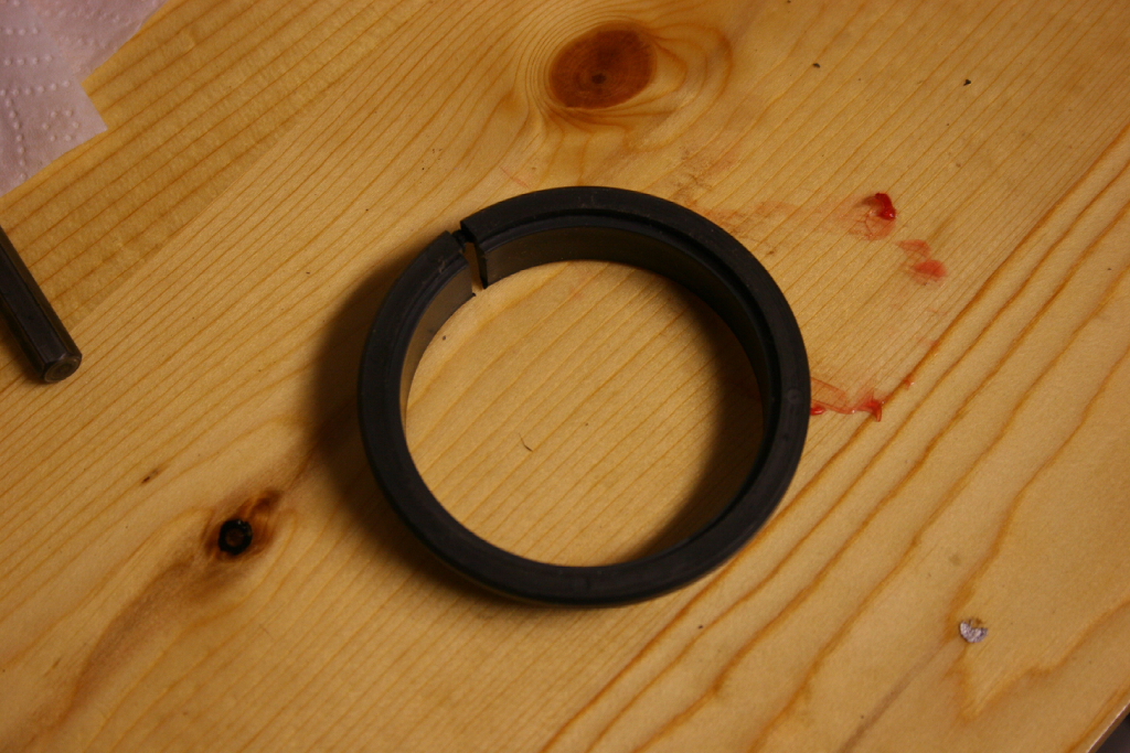
| Now we need to remove the sliding ring gear from the assembly. |
 |
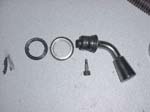
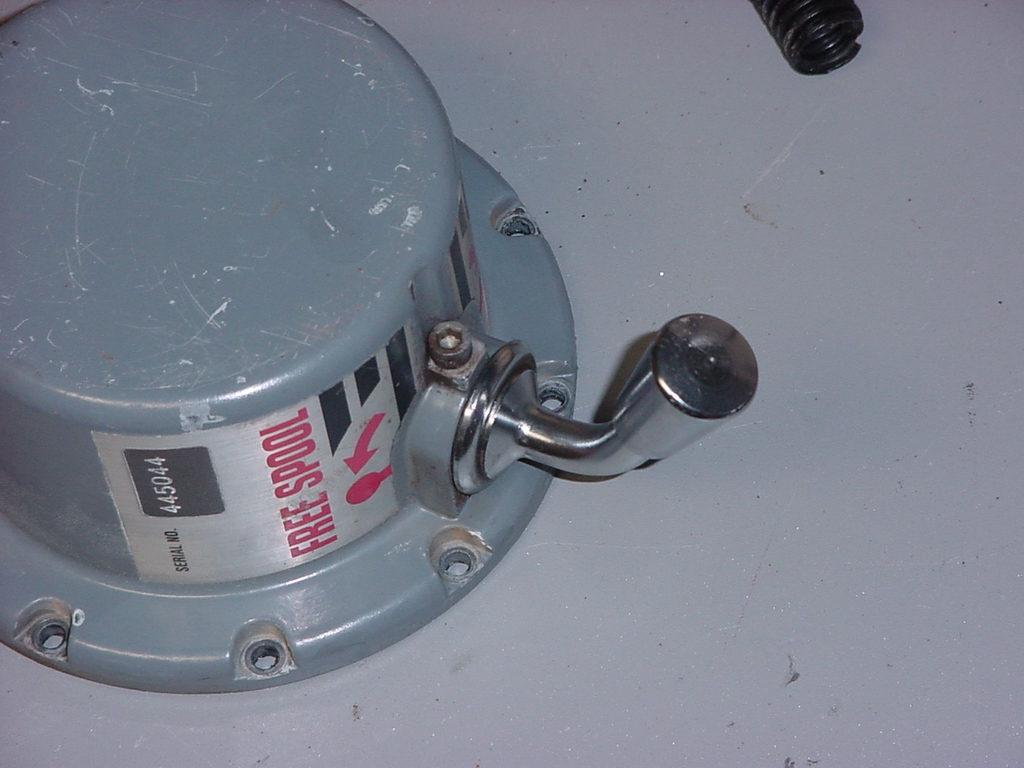
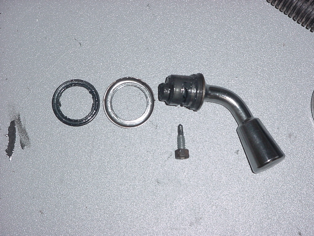
| 14. Remove the clutch lever by removing the clutch lever detent screw with a 5/32" allen wrench. Pull the handle out of the housing and remove the o-ring seal and seal retainer. |
 |
 |
| 15. Remove the sliding ring gear. Note which way the gear came out. The center grove is slightly off center with the thinner section going in first. My top had a slight grove in it. If you reassemble your winch and you can't get it to disengage, you probably put this gear in backwards. |
 |
 |
| Make sure you have cleaned all the old grease out of the parts before you reassembly them. |
| |
| Reassemble the planetary gear assembly: |
| The end housing of the planetary gear set has a thrust washer inside of it. Mine is located underneath a pressed in brass bushing. I managed to pull this bushing out the first time I overhauled the winch, but this time I just checked to see if there was any wear. Even after all this time I didn't see any damage to the thrust washer, so decided not to replace it. Here is what it looks like, just a disk of metal. |
 |
| 1. Grease up the interior of the end housing with some high pressure bearing grease. |
 |
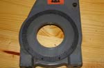
| 2. Coat the sun gear with grease. The picture has just a little to much grease on the gear, but it's in there. Install the gear into the housing. Make sure the center of this gear is not full of grease, you will have a hard time installing the center shaft later. Just use the shaft to push out the grease. |
 |
| 3. Coat the sliding ring gear with a liberal amount of grease. This part rotates. Install it the way that you removed it. Check your notes on this. If you install this part incorrectly you will not be able to disengage the winch. It will remain locked with the gear teeth that were inside the end of the housing. |
 |
 |
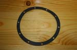
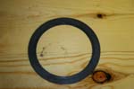
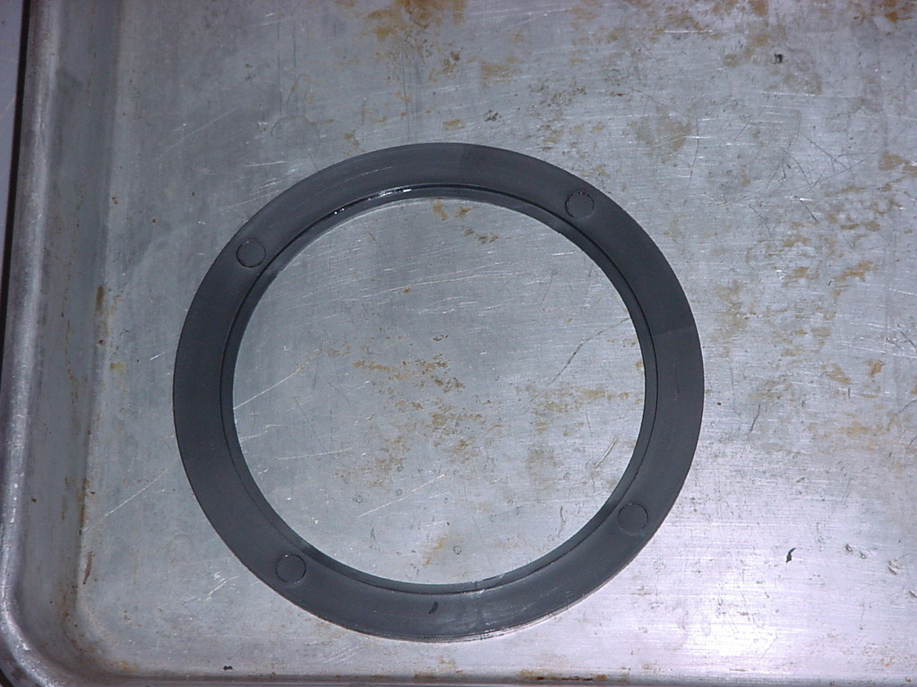
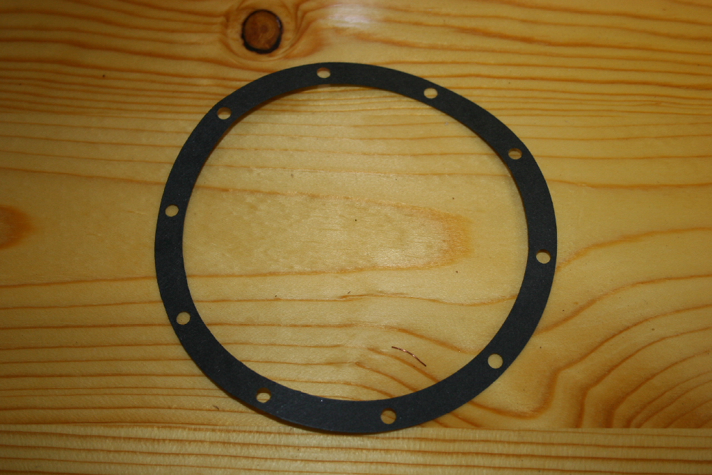
| 4. Install a gasket on the end of the houseing. Line up the bolt holes with the holes in the gasket. |
 |
 |
| 5. Install the ring gear onto the end housing of the planetary gear assembly. If yours has a sticker, make sure the arrow points in the same direction as when you took it off. Mine was pointed towards the front. Line up the bolt holes. |
 |
| 6. Grease up the Stage 1 carrier assembly. |
 |
| 7. Slide it down into place. You may need to rotate it slightly to get it to align with both sets of gears. |
 |
 |
| 8. Grease up the Stage 2 carrier assembly and slid it down into place. You may need to rotate it slightly to get it to align with both sets of gears. |
 |
| 9. Install the plastic thrust bearing with the grove in the same location as during diassembly. Mine was pointed down. This will allow the sliding gear to rise up slightly you disengage the winch. Installed wrong, this may prevent the winch from disengaging, but most likely it will wear and break under the strain. |
 |
 |
| 10. Grease up the Stage 3 carrier assembly and slid it down into place. You may need to rotate it slightly to get it to align with both sets of gears. |
 |
 |
| 11. Grease up and install the drive spline in the end of the case. |
 |
 |
| 12. Test fit the hex shaft into the assembly. Then remove it and set it aside. |
 |
 |
| 13. Set the entire assembly off to the side. We will install the handle later, since having it out seems to make reassembly easier. I recommend placing a piece of duct tape over the opening to keep out any debris. |
|
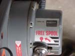
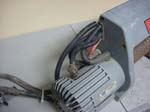
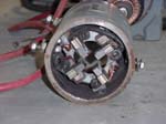
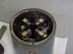
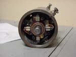
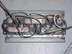
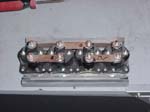
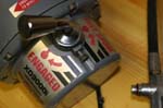
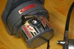
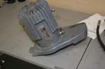
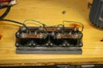
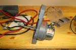
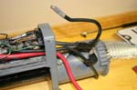
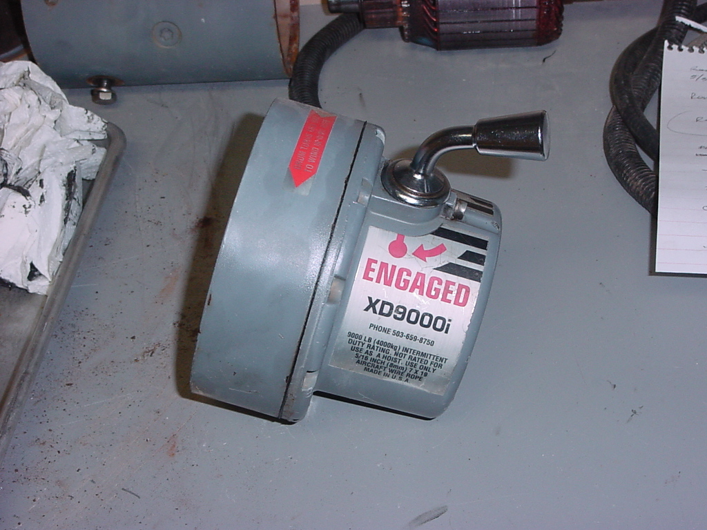
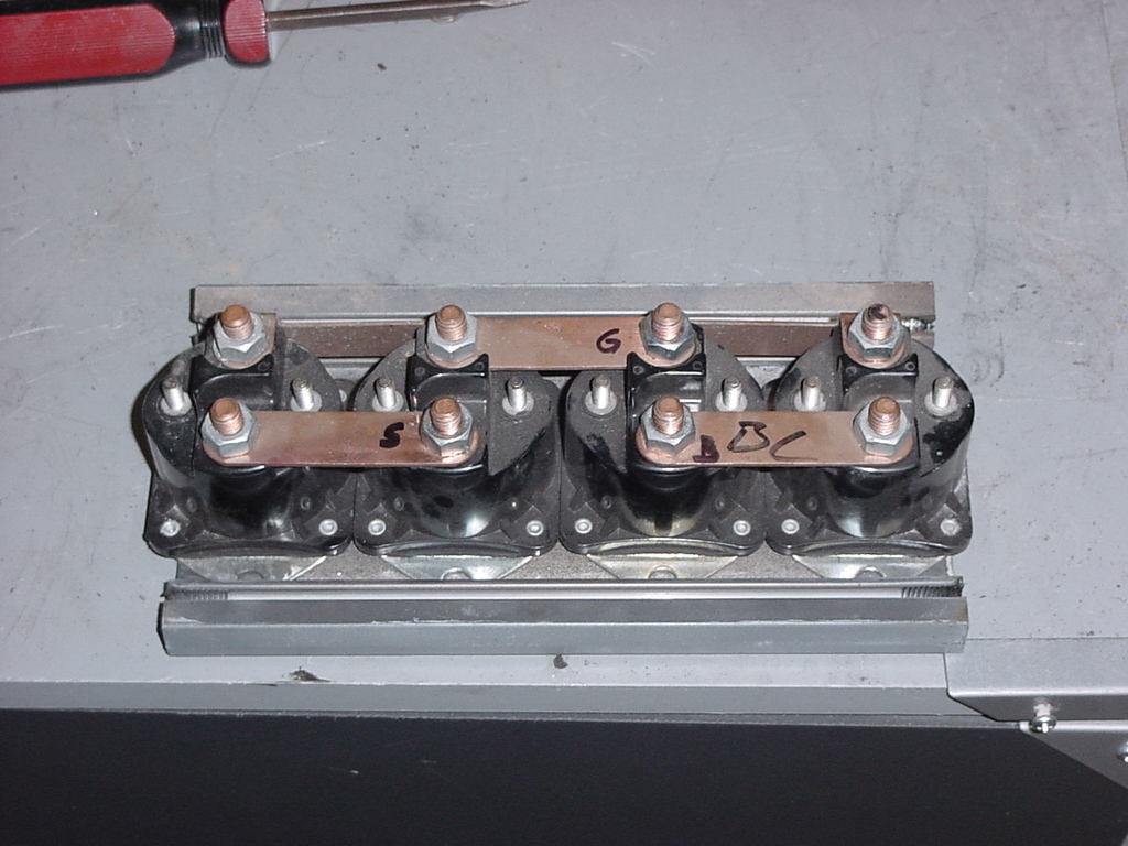
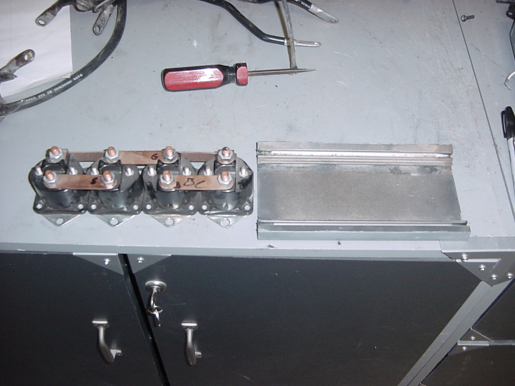
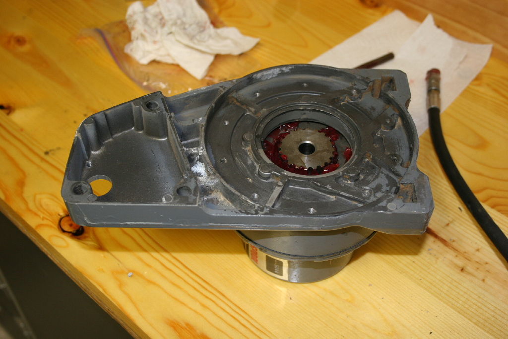
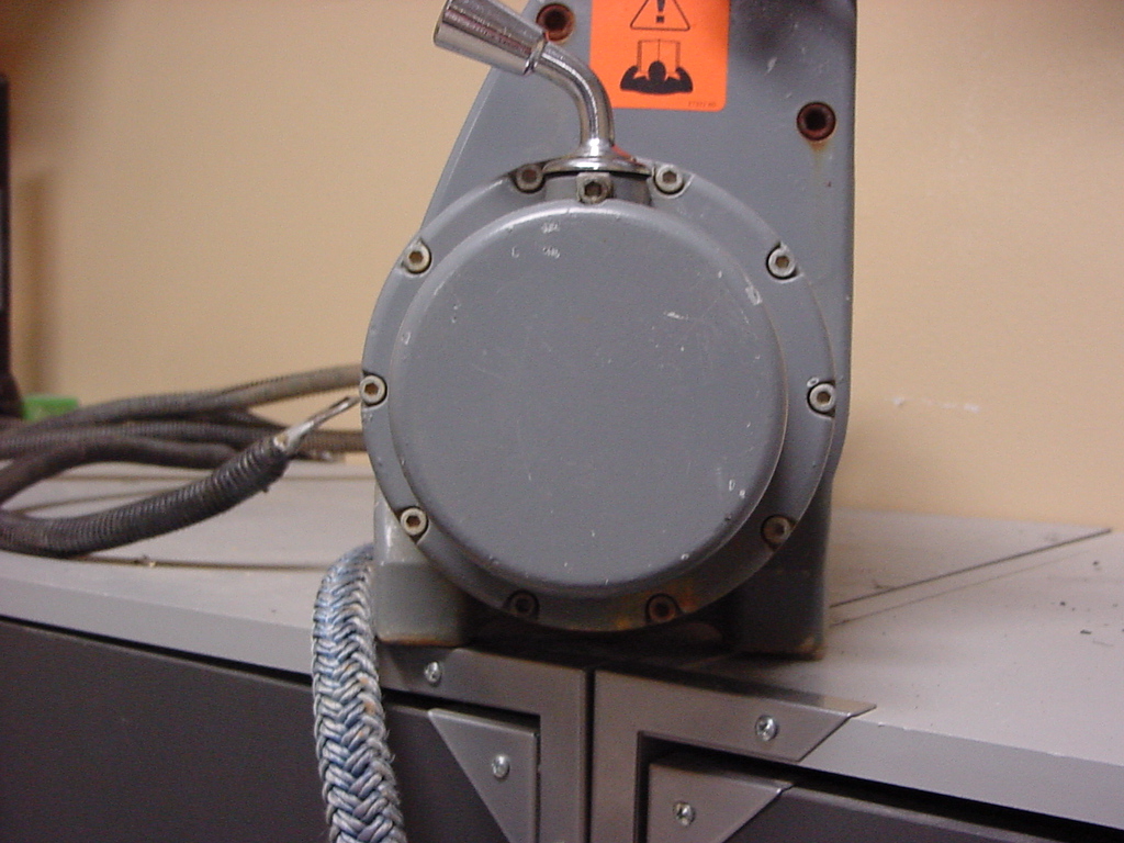
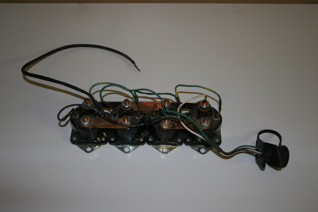
| Winch Drum removal and solenoid disassembly: |
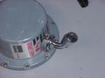
| 1. Remove the solenoid cover. Remove the two upper rear allen head bolts with a 1/4" allen wrench. You might need to loosen slightly (Do not remove) the two bottom bolts. |
 |
 |
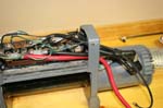
 |
| 2. The cover should tilt forward and then come off. There is a little lip on the front that needs to clear from the bottom plate for the solenoids. |
 |
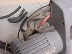
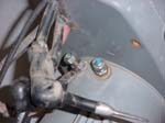
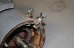
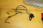
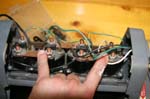
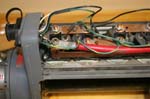
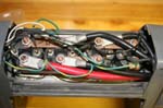
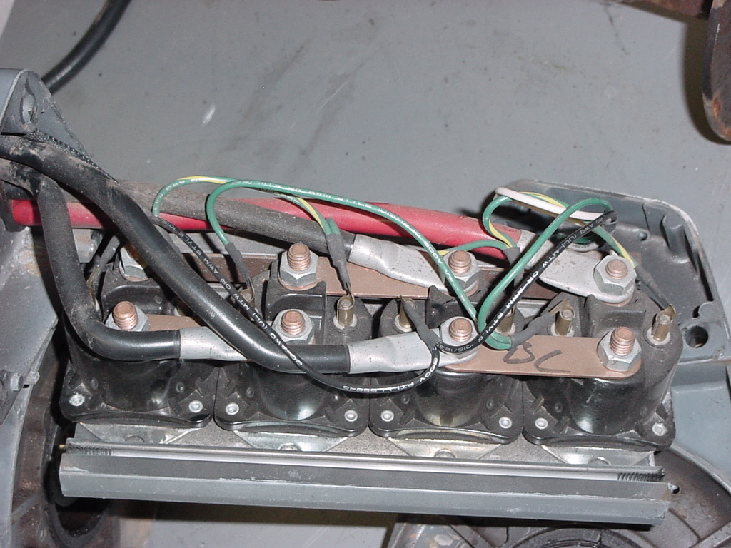
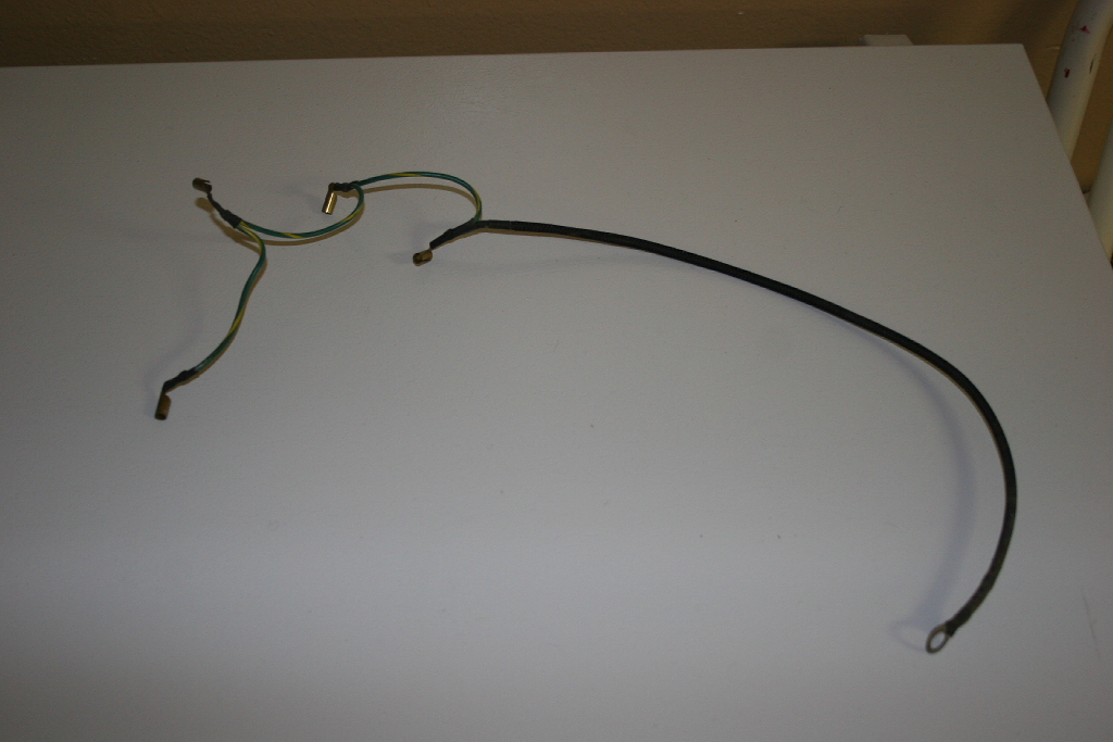
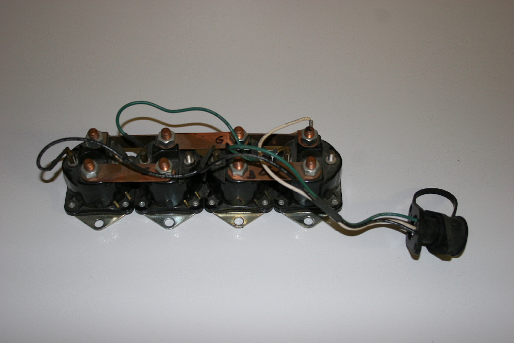
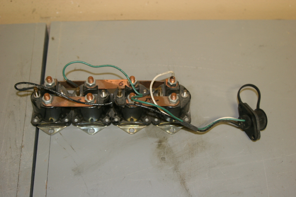
| 3. Mark each wire connection for the power leads and disconnect them. You will need a 1/2" socket or combo wrench. Reinstall the nuts so you don't lose them or get the solenoids out of order later. |
 |
| 4. Make a note as to the order of the wires. This makes reassembly much easier than trying to sort out which wire needs to be where. I'm glad I took a picture, I missed doing this. |
 |
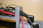
| 5. Remove the rubber grommet from the wires. I found that it push's out from the inside. Pulling on the upper wire does seem to help in getting this out. |
 |
 |
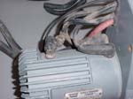
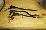
| 6. Remove the power wires from the drum support. Put these aside somewhere so you don't lose them. There will be one small wire that you need to pull back into the housing. |
 |
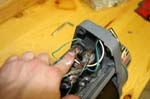
| 7. Remove the two allen head screws holding the socket assembly on to the housing with a 1/8" allen wrench. |
 |
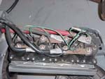
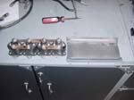
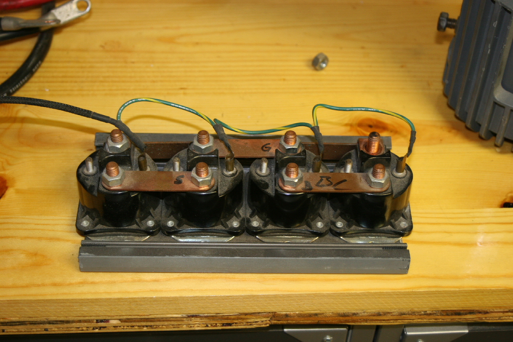
| 8. Mark and disconnect the leads coming from the socket assembly to the solenoids. I found it easier to draw a simple diagram at this point and label it. Feed the wires out of the housing and put the wire harness aside. The only wires you will have left is the ground harness that went out to the motor. Mark and disconnect the leads from the solenoids. Draw this on a seperate diagram. Crossing wires when you reassemble the winch is not health for the solenoids, and they are not cheap. Though they do make a nice blue smoke. |
 |
| 9. Remove the two bottom screws from one side and remove the drum support. The drum assembly can be pulled out of the other side at this point. Remove the two screws from the other side while supporting the solenoind assembly. |
|
|
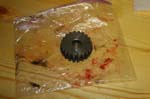
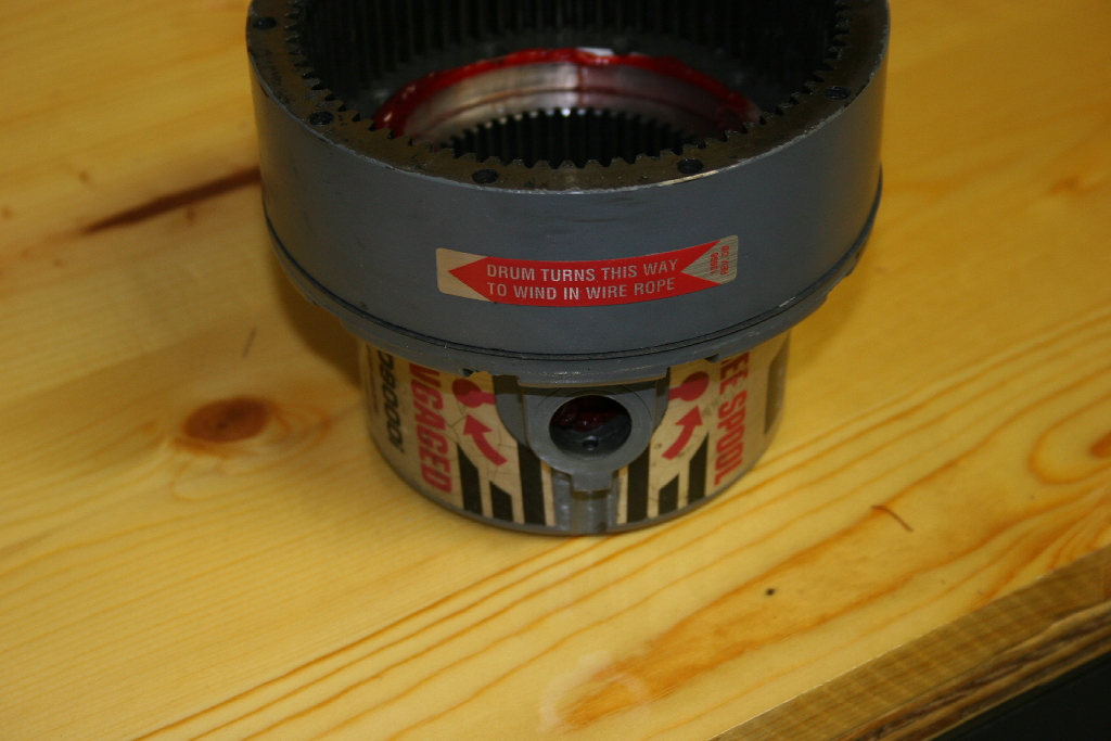
| 10. Put the drum assembly and solenoid pack off to the side. Be careful with the drum, it has a brake assembly inside of it that you do not want to have slide out and hit the floor. It's about $120 for a new one. |
 |
 |
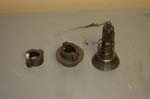
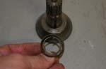
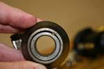
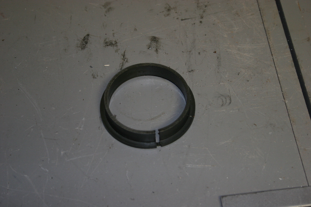
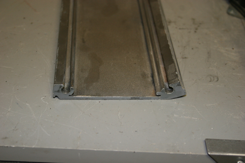
| 11. Remove the plastic drum bushing from the drum support ends. It has a split in it that fits around a tang in the housing. |
 |
 |
 |
 |
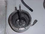
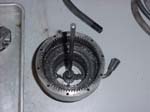
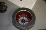
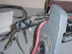
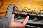
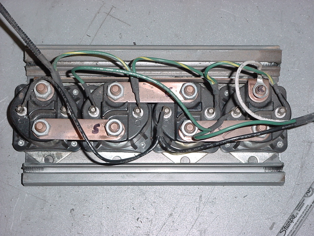
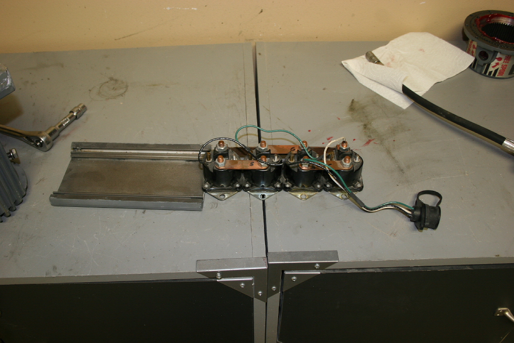
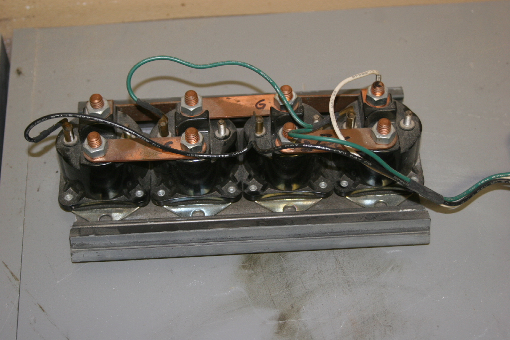
| 12. Remove the solenoid pack from the bottom plate. The pack slides out of the plate. You may not need to do this, I just wanted to clean out all the debris that was underneath it. |
 |
| 13. Clean all the parts. Inspect the solenoid pack for any signs of charring or damage. Inspect the wires for corrosion, or breaks. I needed to seal the ends of a couple of wires with some liquid electrical tape. |
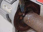
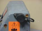
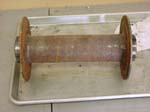
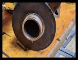
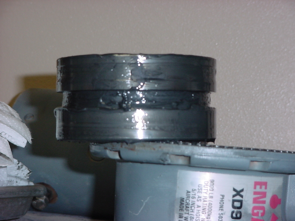
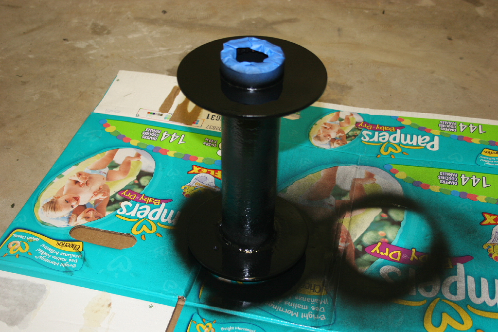
| 14. My winch drum was crusted over with debris, and rust. I took a wire wheel to it to clean it all off, then painted it with some high temp engine paint. I'll see how well this lasts. |
 |
 |
 |
| |
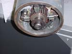
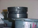
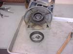
| Brake removal and disassembly: |
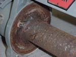
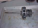
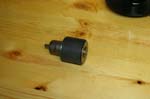
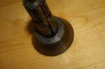
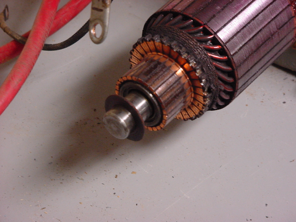
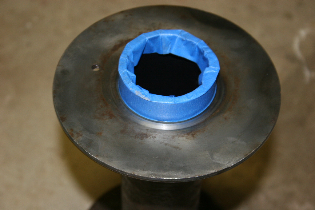
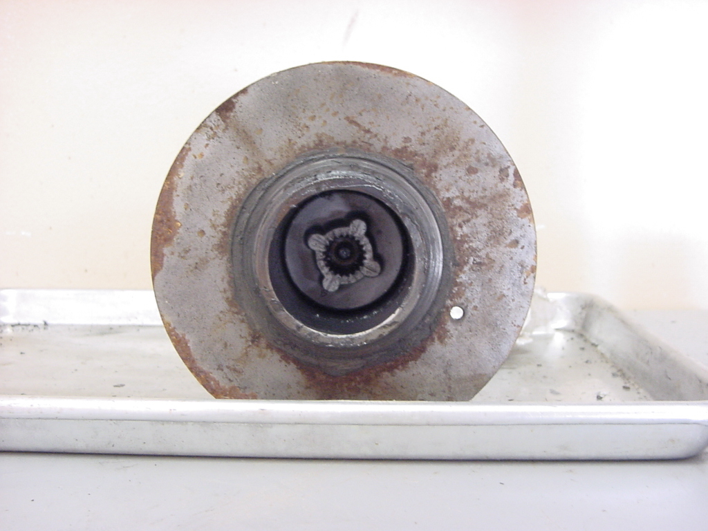
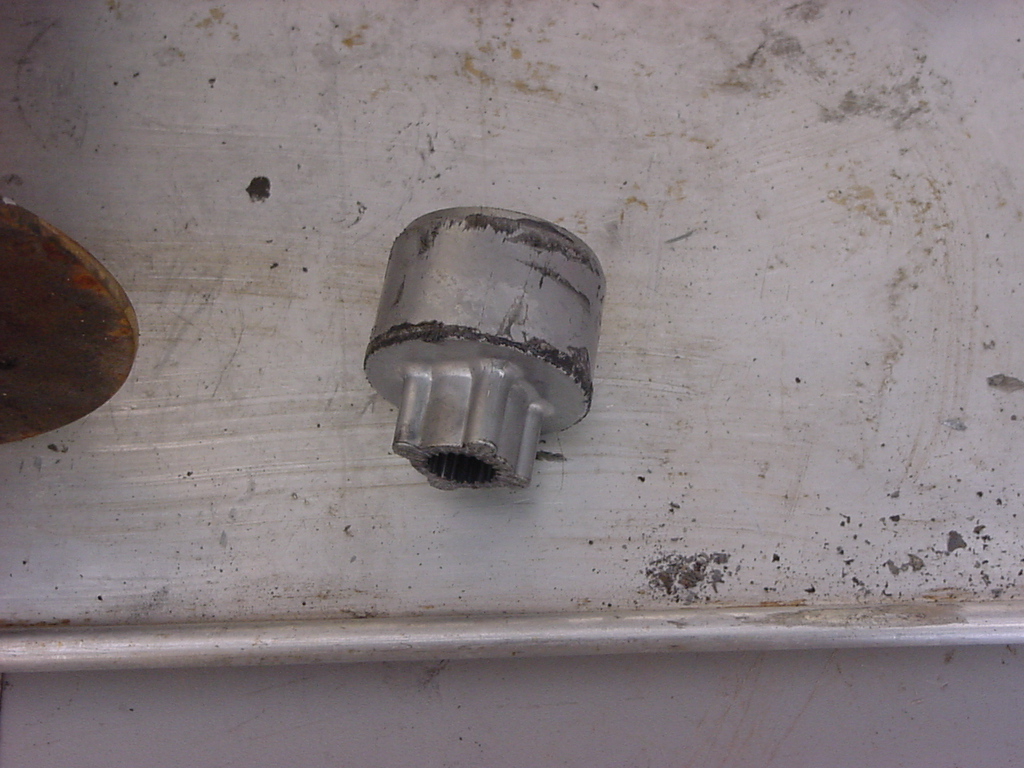
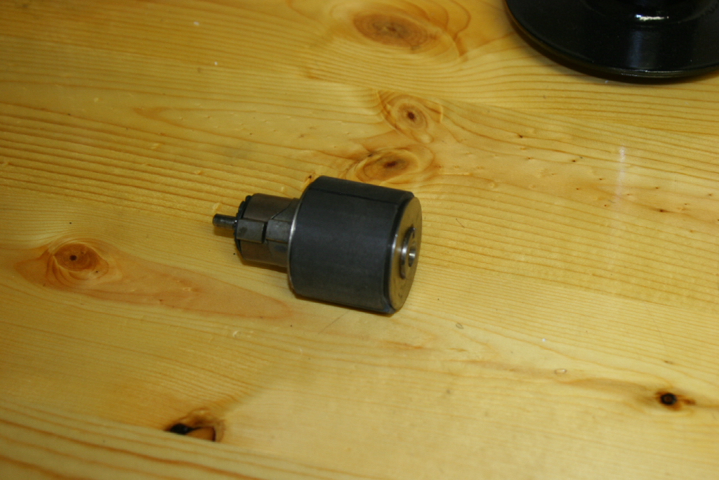
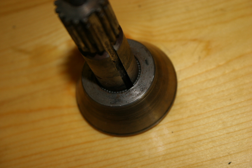
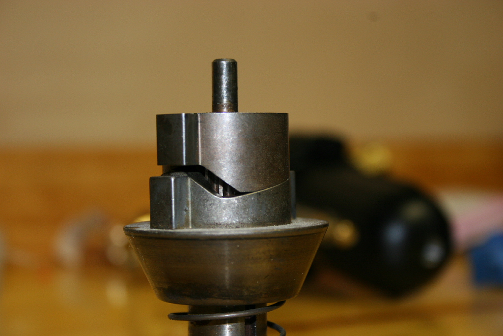
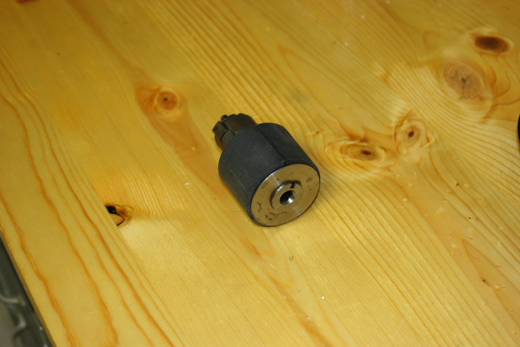
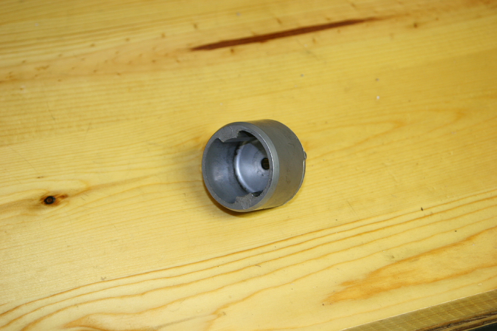
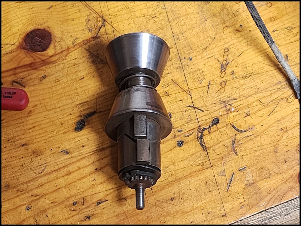
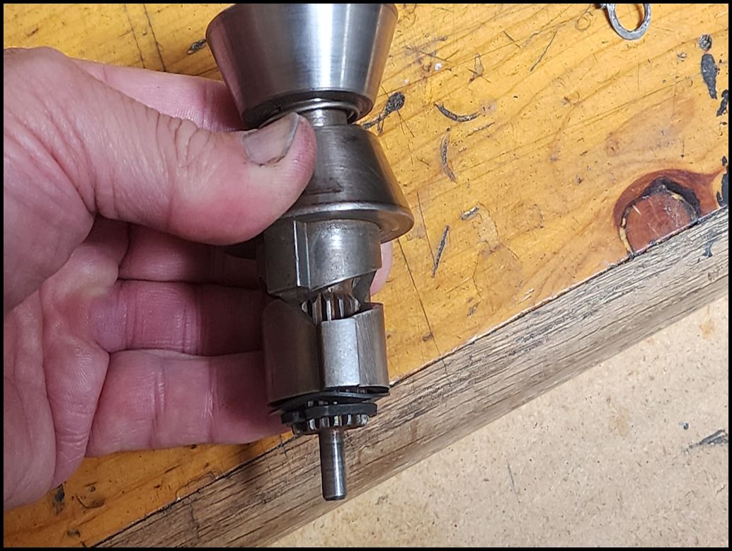
| 1. Remove the motor coupling from the end of the drum. You can either reach in and grab it with a needle nose pliers, or tilt the drum and gently tap it out. It should slide out depending on how much crud is inside. |
 |
 |
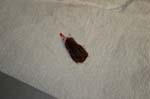
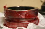
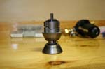
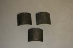
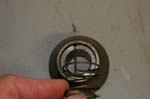
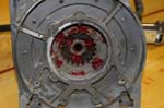
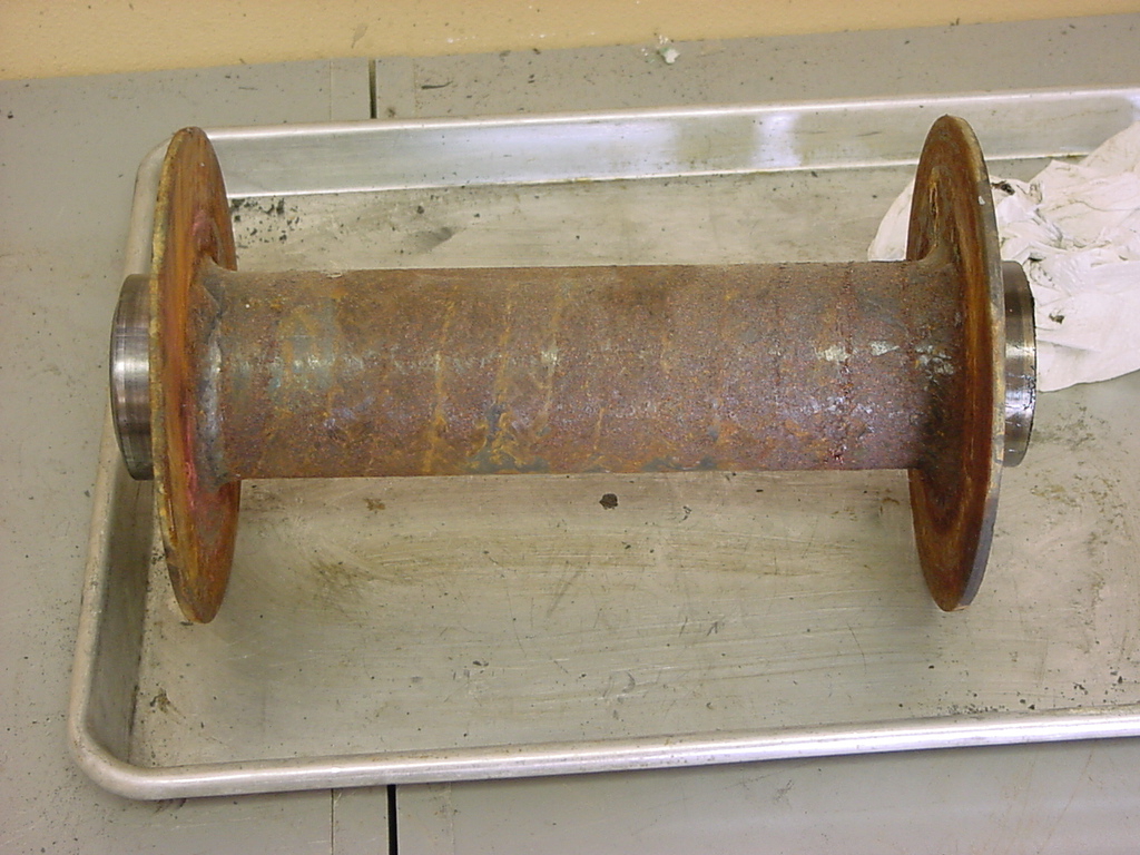
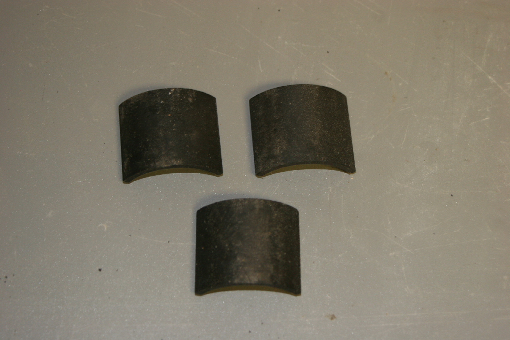
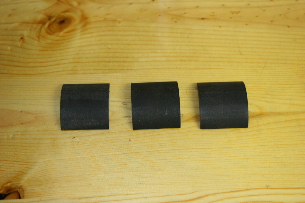
| 2. Tap or push the brake assembly out. Mine actually slide out this time, but I had to insert a wood down from the other side the last time and tap it out. Don't just let it fall out, there are three brake shoes on the assembly that will fall out. If one of these breaks, it's $120 for the assembly. Mine were still in good condition after all these years. They just needed to be cleaned off. |
 |
| This is what it looks like as it comes out, and with the brake shoes off. The shoes are not held on by anything. |
 |
 |
| 3. Set the brake shoes aside, we will clean these up later with some fine sandpaper. |
 |
| 4. Remove the snap ring from the top with a pair of snap ring pliers. Remove the spring washer from the top and the two interlocking halves of the brake assembly. |
 |
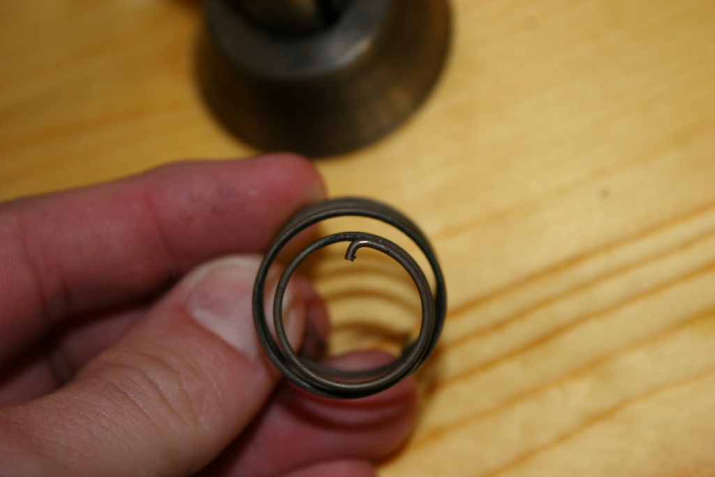
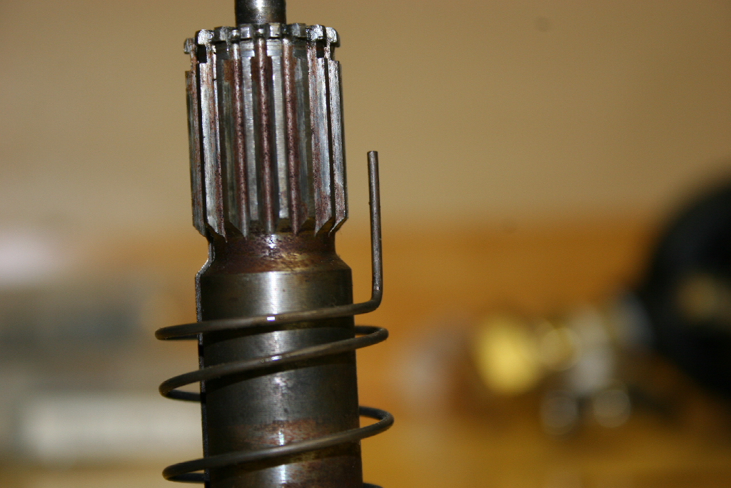
| 5. Remove the spring from the brake assembly. Note the long end of the spring fits into the upper cone and the bottom tip of the spring fits into the grove on the lower cone shaft. |
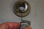 |
 |
 |
| 6. Clean up all the brake parts. |
 |
| 7. Clean the brake shoes with some 200 grit sand paper or higher. You just want to remove the crud from the shoes, not any material from them. |
 |
| |
| Brake reassembly: |
| 1. Find all your parts for your brake assembly. They should be in one location. I managed to misplace a brake shoe. The whole assembly is $120. Luckily I managed to find it after a days searching and cleaning the garage. How it got under the tool box on the other side of the workshop I don't know. |
|
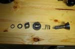 |
| 2. Install the spring on the lower cone. The small tab on the spring goes in the slot. The long end will point up. |
 |
 |
| 3. Install the upper cone on the lower cones shaft with the long tap on the spring through the hole in the cone. |
 |
 |
 |
| 4. Install the upper cam on the upper cone. Cams will go together. |
 |
| 5. Install the spring washer and snap ring. You will need to push down on the upper cone to expose the snap ring slot. |
|
| 6. Here is what it will look like when it is assembled. The brake shoes are not held in by anything so are just balanced there in these pictures. |
 |
|
| 7. This is what it will look like sliding into the winch drum. Do not slide it in yet. |
 |
 |
| |
| Winch reassembly (Planetary gear to housing): |
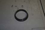
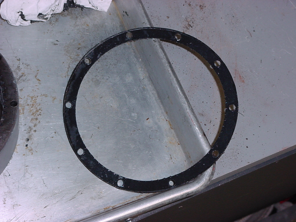
| 1. Install an new gasket on the end of the drum support. |
 |
 |
 |
| 2. Place the drum support over the planetary gear assembly and flip the entire assembly over. I tried it the other way and had the gears fall out. You may still have the drive spline fall out. |
 |
 |
| 3. Install the 10 Allen head screws holding the planetary gear assembly to the drum support. Install them all then tighten them in a star pattern. You will need a 5/32" Allen wrench |
 |
 |
 |
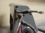
| 4. Stand the assembly on end to expose the clutch lever hole. |
 |
| 5. The clutch lever has a cam on it to move the sliding gear back and forth to engage and disengage the winch. Place the seal reatainer and o-ring seal over the end of the lever. |
 |
 |
| 6. Apply a liberal amount of grease to the end of the clutch lever. |
 |
| 7. Insert the clutch lever into the end housing. You may need to twist it to get the cam to align with the grove in the sliding gear. |
 |
| 8. Install the clutch lever detent screw in the end of the housing. You will need a 5/32" allen wrench |
 |
 |
 |
| 9. Install the drive spline in the end of the planetary gear assembly if it fell out. |
 |
 |
| 10. Install the plastic drum bushing in the end of the drum support. Align the slot in the bearing with the tang in the housing. |
 |
 |
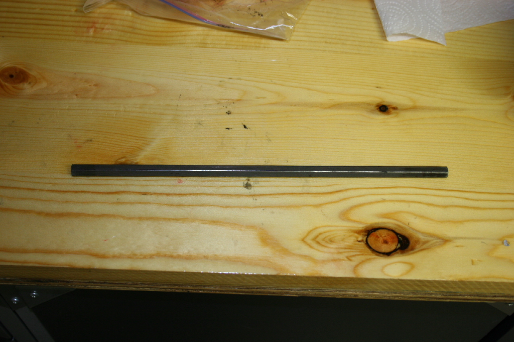
| 11. Install the hex shaft though the center of the planetary gear assembly. |
 |
| |
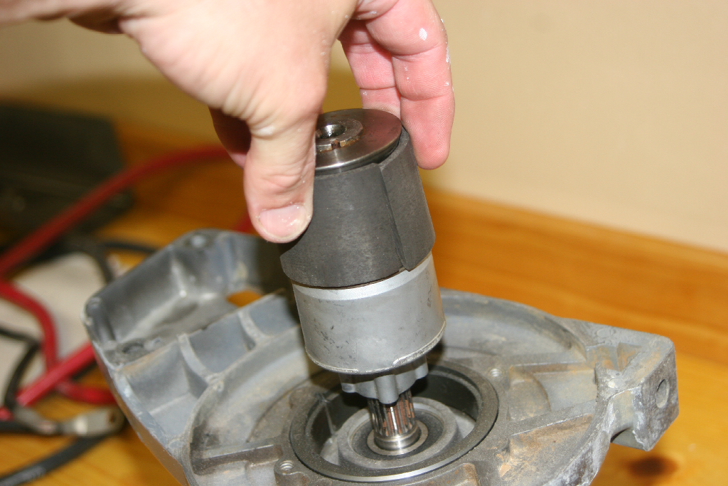
| Winch reassembly (motor gear to housing, brake and drum): |
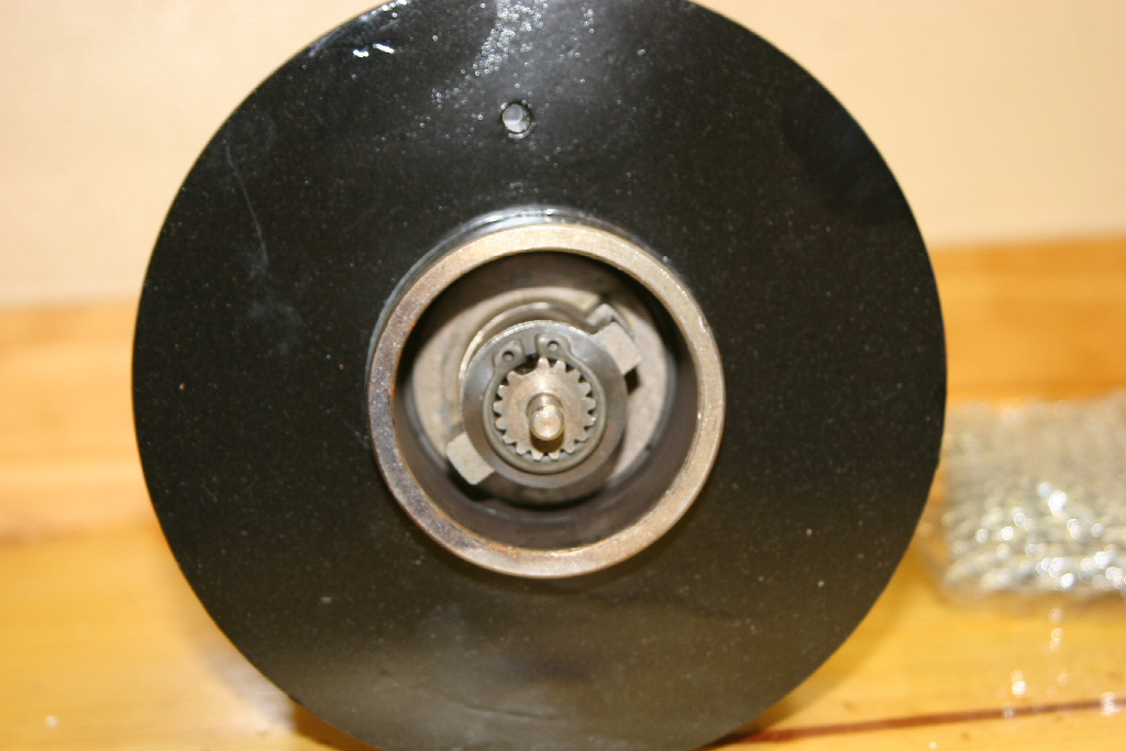
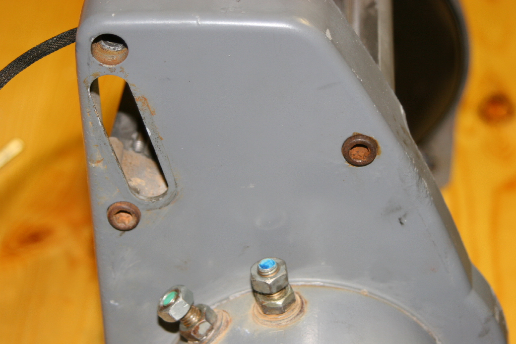
| 1. Line up the locater pin on the motor housing with the hole on the drum support. You can see the hole in the upper left of the picture. |
 |
 |
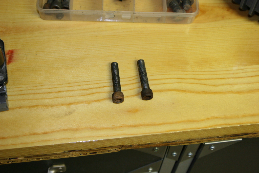
| 2. Install the two motor screws and tighten with a 3/8" socket. |
|
|
| 3. Flip the assembly on end so that it is sitting on the motor. |
 |
| 4. Install the plastic drum bushing in the end of the drum support. Align the slot in the bearing with the tang in the housing. |
 |
 |
 |
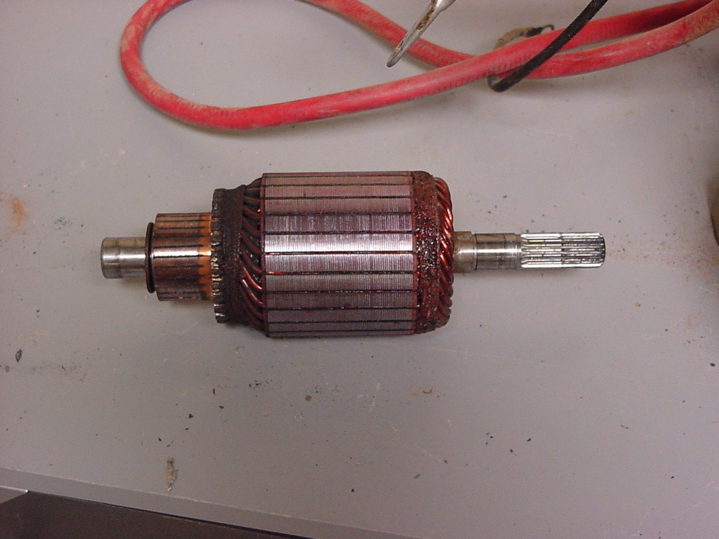
| 5. Insert the motor coupling over the end of the motor splined shaft. |
 |
 |
 |
 |
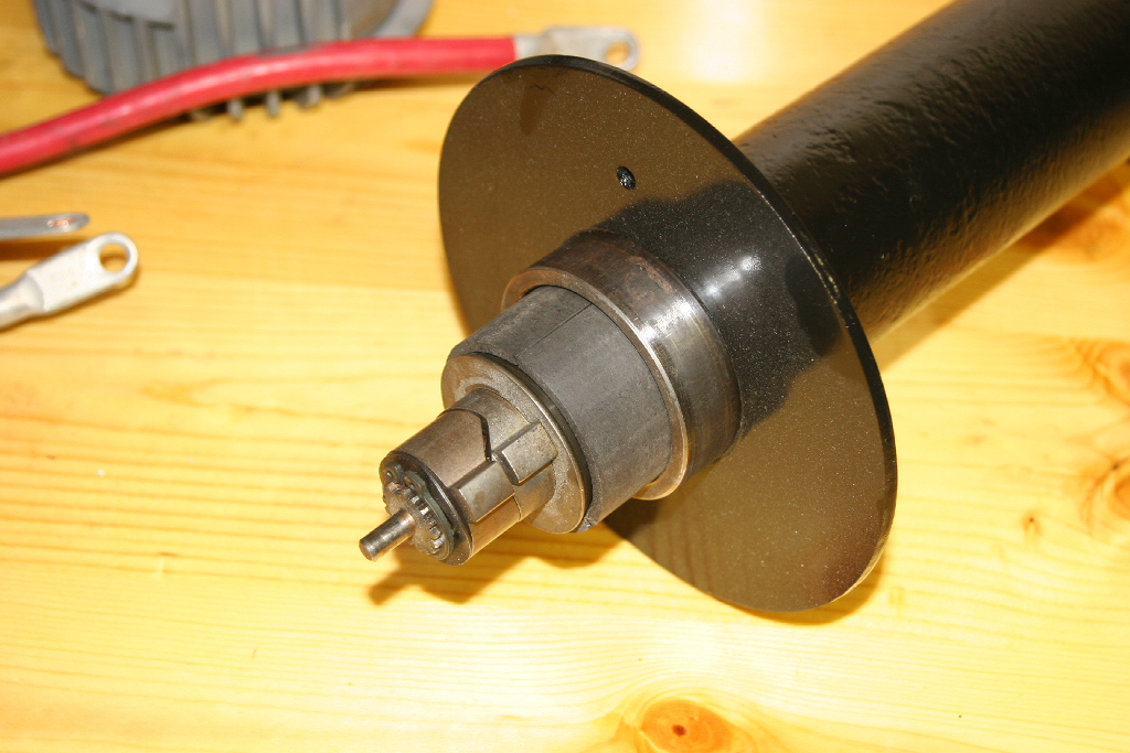
6. Proper installation of the brake is important or you run the chance of burning out your motor because the brake will stay engaged, or drag. The one thing you will notice is that it takes a lot of force to pull the cable out when the drum is disengaged. The brake assembly will slide into the end of the drum.
Note: I have tried installation 2 ways and I don't know which one works better. First way is the following steps, the other way is to install the drum onto the gear side first and then slide the brake assembly into the drum and lock it into the metal shaft coming out of the gear box. |
 |
| 7. Start with the brake assembly in it's neutral position and the brake shoes set aside. Rotate the lower cone 180 degrees counter clockwise (to your left) until the index lugs line up again. Hold the lugs in this position. |
 |
 |
 |
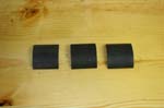
| 8. Now the hard part. Carefully, while holding the lugs in position, pick up the three (3) brake shoes and set them in place. I was able to hold all the parts in position with one hand once I got it assembled. |
 |
| 9. Slide the brake assembly into the end of the drum, I pushed it all the way in until only the pin was sticking out. |
|
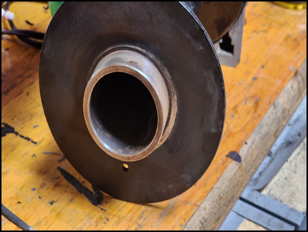
| 10. Slide the drum with the brake assembly down over the brake drive and into the plastic bearing in the end of the housing. |
This is how the brake sits on the drive. |
 |
| |
| Winch reassembly (solenoid and housing): |
| 1. Slide the solenoid pack into the bottom plate. |
 |
|
|
| 2. Reconnect the ground wire harness to the solenoid pack |
 |
 |
| 3. Attach the solenoid pack to the motor side with two allen head bolts. Just snug these up since you may need to adjust everything later. |
 |
 |
 |
| 4. Carefully tilt the entire assembly down on to the workbench. |
| 5. Insert the planetary gear assembly onto the drum. The shaft will slid into the end of the brake assembly. If you have difficulty getting the end on over the drum, you might want to try to insert the shaft into the brake assembly and then slide the planetary gear assembly over it. |
 |
 |
| 6. Attach the solenoid pack to the planetary gear side with two allen head bolts. Just snug these up since you may need to adjust everything later. |
 |
 |
| 7. Insert the socket assembly wire harness through the opening in the housing and secure the socket assembly with the two allen head screws. You will need a 1/8" allen wrench. |
 |
 |
 |
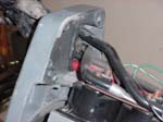
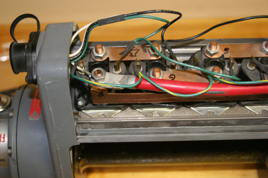
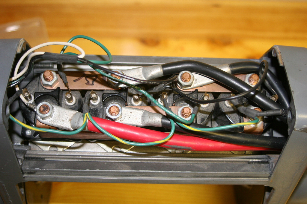
| 8. Follow the wiring diagram and reconnect the wires to the terminals on the solenoids. |
 |
 |
 |
| 9. Slip the ground wire out through the opening on the motor side of the housing. |
 |
| 10. I choose to reattatch the power wires to the motor first and then to the solenoid. It can be done, but it's easier to attatch them to the solenoids first. Match the cables with their respective motor terminals and install the nuts on top. Do not tighten. |
 |
 |
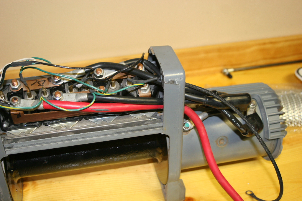
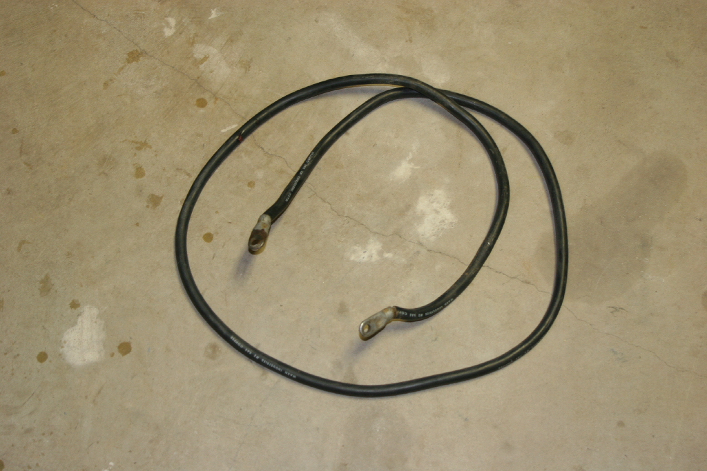
| 11. Attach the red power cable to the solenoid. This was the bottom cable on my winch. You will need a 1/2" socket |
 |
 |
| 12. Reattatch all the motor leads to their respective solenoid terminals. Tighten with a 1/2" socket. |
 |
 |
 |
 |
| The small solenoid ground wire should be on top, or in the same location as noted during disassembly. |
 |
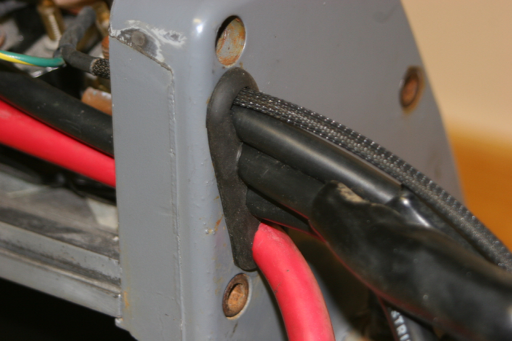
| 13. Install the rubber grommet around the wires. The cut goes towards the bottom and the small lip towards the back of the winch. The full seal lip should be on the outside. |
 |
 |
 |
 |
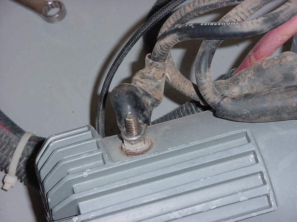
| 14. Tighten up the cable nuts on the motor terminals and push the boots over the end of the cables. I recommend coating the terminals with a little dielectric grease to prevent corrosion. You will need a 1/2" socket. |
 |
 |
| 15. Install the Negative cable and solenoid ground wire to the bottom terminal on the motor. Tighten down the bolt with a 1/2" socket. |
 |
 |
 |
 |
| 16. Install the solenoid pack cover with the two remaining allen head bolts. Tighten up all the bolts holding the ends to the solenoid pack. You will need a 1/4" allen wrench. |
 |
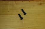
| 17. Reinstall the bolt for the cable hold down so that you don't lose it. Mine was a 5/32" allen wrench. |
 |
| 18. Reinstall the square nuts in the base of the winch. |
 |
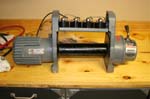
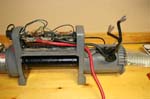
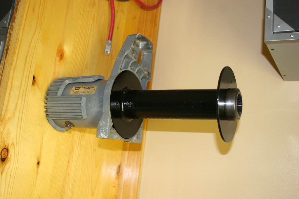
| 19. Finished product. You can disengage the winch and try to turn the drum. This will tell you that you got everything mechanically right. I still need to repaint the winch again, so a little light sanding, some taping and a coat of paint will follow. |
 |


