Now that we have gotten the Skid plate installed we can
move on to our arms. This is probably the second hardest part of the whole
installation from the stand point of the arms being heavy and cutting and
grinding on those brackets is a real pain. This was an all day
project. I used electric's and muscle power. If you had a compressor
with a die grinder it would go much faster.
Rear
Arm Installation:
If you have the jack stands available
to support the entire vehicle in front of and behind the skid plate,
then you may want to strip the entire suspension off before you do
any cutting. This does make it easier to move the axles around.
Just be careful of things that are attached to the axle when you do
this. I decided to try it without doing this step. The
RE instructions are kind of vague on which way to do it. They
mention removing suspension items, but if you are doing the upgrade
you don't. |
| 1. I decided to start on the rear first since it was going to be
the most cutting. I carefully read the RE instructions all 1
page for both front and rear. Now I didn't remove the rest of
the suspension while I did this, but I had jack stands all over the
place and the floor jack underneath stuff. |
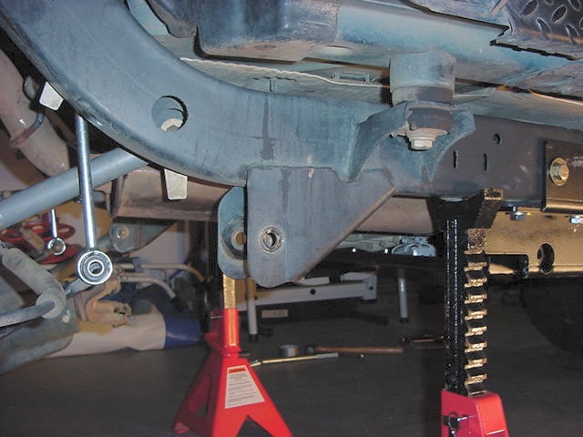
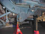
| 2. I jacked up the rear end and removed the tires, I then lowered the
rear end down so that the rear axle was almost all the way to the
ground. I supported it with jack stands behind the skid plate,
and another set positioned under the rear bumper. These didn't
actually touch, but they were fairly close at full extension.
I left the floor jack under the axle. I did play with this setting
a couple of times before I found a good position to allow the axle
to relax. |
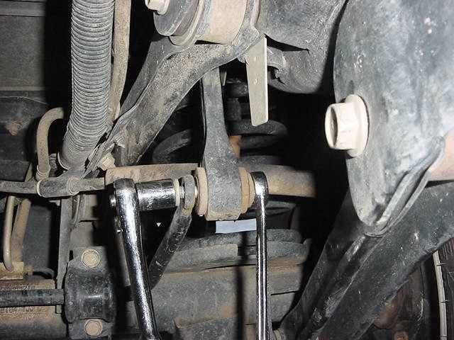
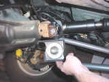
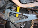
| 3. I disconnected the rear sway bar links with a 15mm socket and
18mm wrench. More so that they were out of my way than anything
else. |
 |
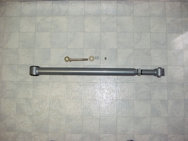
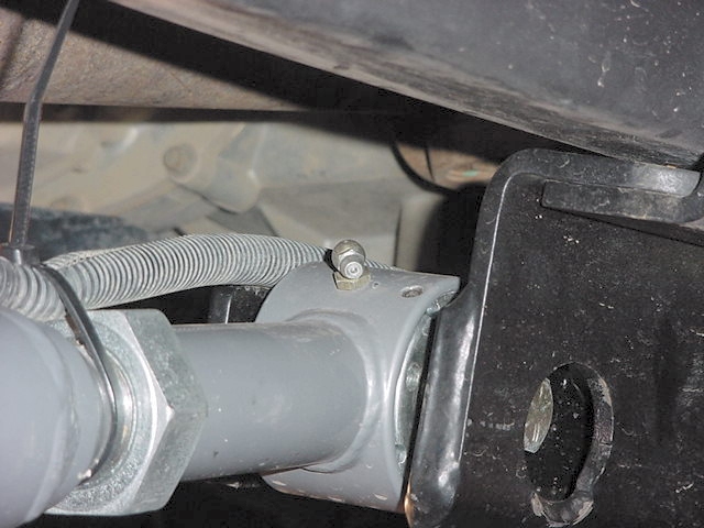
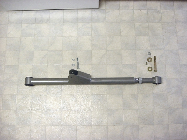
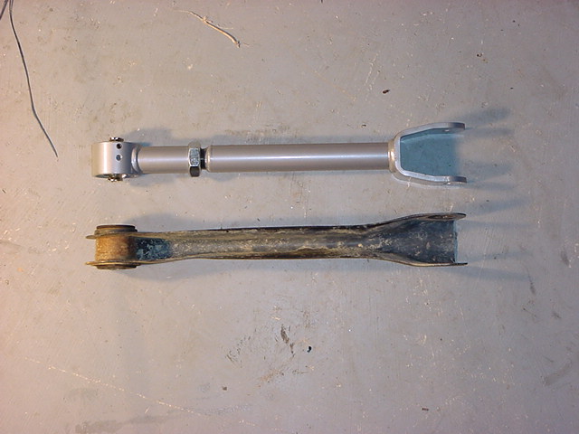
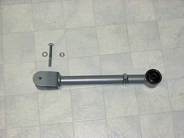
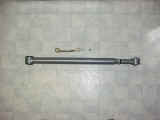
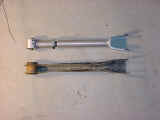
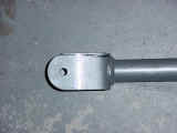
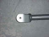
| 4.
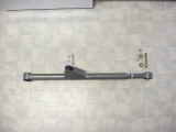
I installed the Zerks in the upper and lower arms. The upper
arms have 2 Zerks. You will need a 3/8" wrench to install
the 90deg Zerk in the adjustable section and a 5/16" wrench to
install the other one. The lower arms only have 1 Zerk.
You will need a 3/8" wrench to install the 90deg Zerk in the
adjustable section. This section will end up having the Zerk
on the bottom. |
 |
 |
 |
|
| 5. I then removed the lower control arm from one side. I started
with the passenger side since there wasn't a whole lot of stuff attached.
You will need a 21mm Socket and wrench (can substitute a 7/8"
wrench) for the lower control arms. I left the upper arms in
until I finished cutting off the lower bracket. |
 |
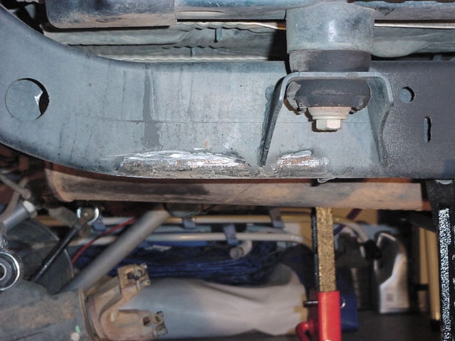
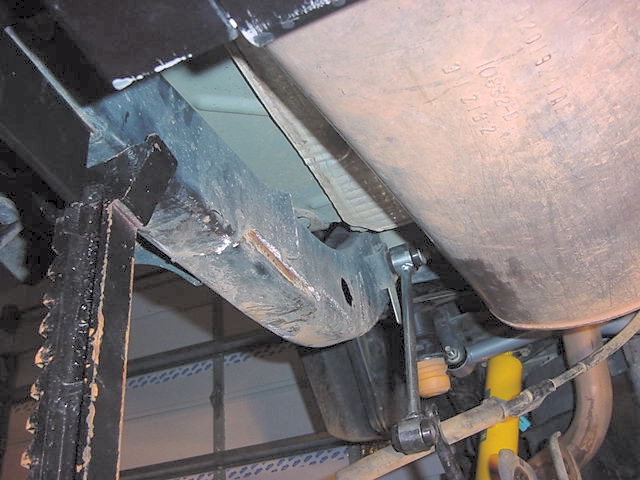
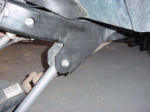
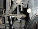
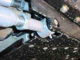
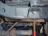
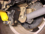
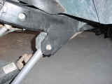
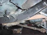
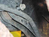
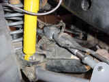
| 6. Now time to break out the Power Tools. The RE instructions say
to remove just the lower control arm brackets. Okay this makes
sense. So I first decided to try and grind off the weld on the
outside of the frame. Well that was a lesson in futility.
So I decided to go the easy route and cut off front edge and the outer
side of the bracket. This allowed me to get a pry bar in and
bend the bracket down. I just used a pry bar to move it back
and forth until I snapped the weld on the inner side. Once that
was done, I ground down the outer weld a little more and just pried
on the lip of what was left, it snapped fairly easy. Now all
you need to do is grind down the welds, and spray it with some frame
black spray paint or if your like me whatever black spray paint you
had on the shelf. |
 |
 |
| 7. Now remove your upper control arm. You will need a 15mm
socket and wrench to get these bolt out. Now if you are removing
your stock arms, you will also need a 13mm socket or wrench to remove
the emergency brake cable bracket from the arms. |
|
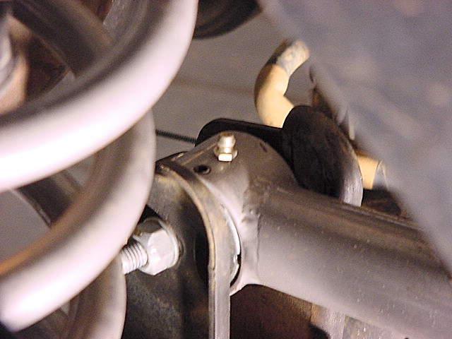
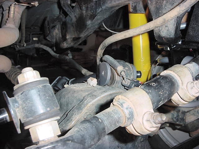
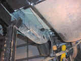
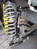
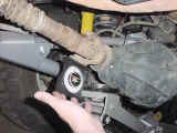
| 8. Now before I installed the lower arm, I decided to test fit the upper
arm since the upper control arm bracket seemed to be sitting pretty
close to it's line of travel. Once I got the arm up there I
saw that it was uncomfortably close, you could stick a pencil between
the arm and the bracket. To close, so out came the Sawzall again.
This time I just hacked off the bracket and cleaned up the edges.
Some day in the future when I have a compressor I'll get in there
and smooth it out. |
 |
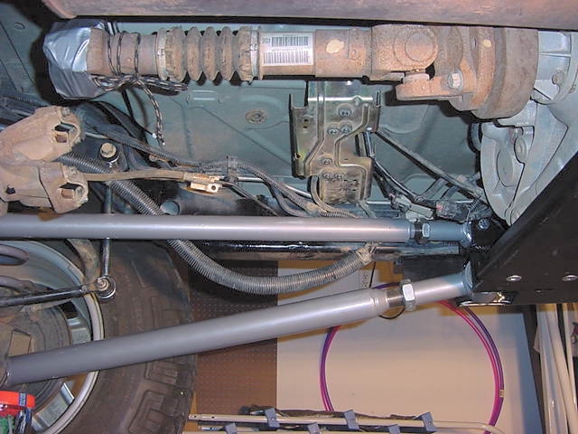
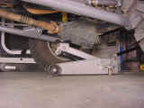
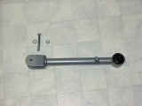
| 9. I then adjusted the lower control arm to the RE setting of 33 1/4"
and installed it. You may need to remove the other lower control
arm at this point so that you can get this one in. You will
need to reuse the factory axle bracket bolt so you will need the 21mm
socket and wrench (can substitute a 7/8" wrench). On the
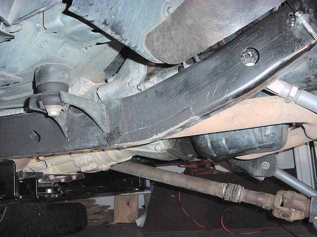
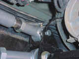
skid plate side you will need a 7/8" wrench for the nut and a
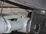
13/16" socket for the bolt head. This is a real joy to
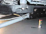
get in. If you look at the skid plate, you will notice that
the outer hole where the bolt and washer go through isn't quite round
since it is right at the bend point. It is a little tricky to
get the washer in without dropping it between the sections of the
skid plate. If you do this by accident, you can work the washer
out with a scribe. Once I got the control arm to line up with
the hole, you will need to install a washer on the bolt and insert
the tip of the bolt into the hole, now work the washer into the hole
on the skid plate and install the bolt the rest of the way.
I then loosely installed the nuts on both bolts, but didn't tighten
them down. My length is currently 33 1/2".
I will need to readjust this when I fine tune the suspension.
I'll update the length at that time. I intend to get it fairly
close to stock length, so that when the tire stuffs into the wheel
well it will go into the center of it. |
 |
 |
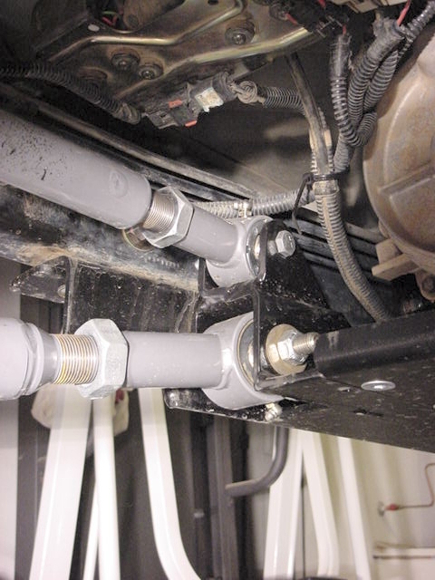
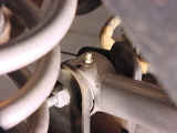
| 10.
I couldn't install the upper arm just yet since I needed to rotate
the pinion up and I still had the other upper arm installed. So I
just installed it on the skid plate side and left it sit on top of
the upper axle bracket. You will use the new bolts that came
with the RE kit. These require a 17mm socket and wrench to install.
The skid plate bolt goes through from the inside, so you don't have
a lot of room to get the washer and nut on between the bracket and
skid plate. Good to have an extra hand here to hold up the arm
while you get your hands into this area. The Zerk fitting on
the adjustable end points upwards. You will have the room to
rotate the arm to adjust the length, so it's not that much of a problem.
My length is currently 33 1/2". I will need to readjust
this when I fine tune the suspension. I'll update the length
at that time. I intend to get it fairly close to stock length,
so that when the tire stuffs into the wheel well it will go into the
center of it. |
 |
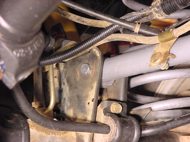
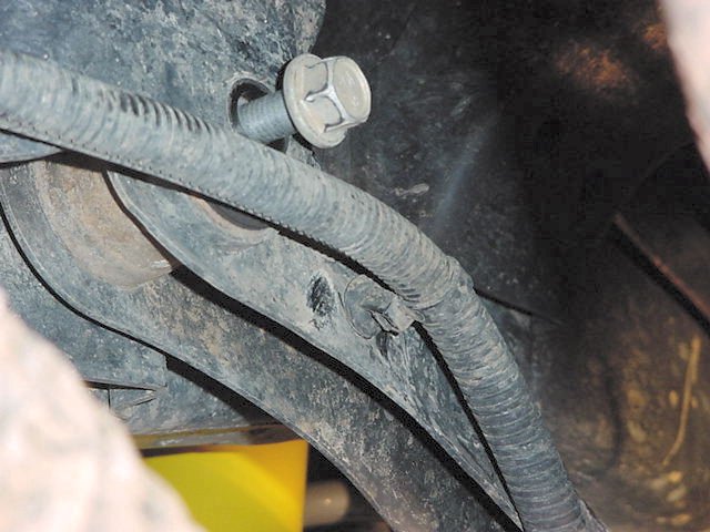
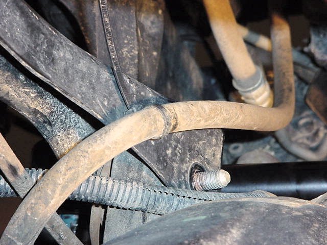
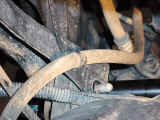
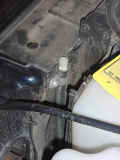
| 11. Now repeat steps 5-10 on the Driver side. Be very careful on
this side, the brake and fuel lines run right along the frame.
You will need to pry the bracket that is holding these lines off the
top of the Upper Control Arm frame bracket. You will also need
to remove the rear brake line from the bracket. Use a T-40 Torx
to remove the bolt holding it on. Once you get all of these
clear, you can cut off the upper bracket carefully. |
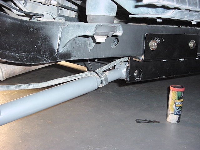
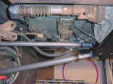
| 12. At this point you should have the 2 lower control arms installed
and the 2 upper control arms bolted into the skid plate. You
will need to rotate the pinion up to install the upper arms into the
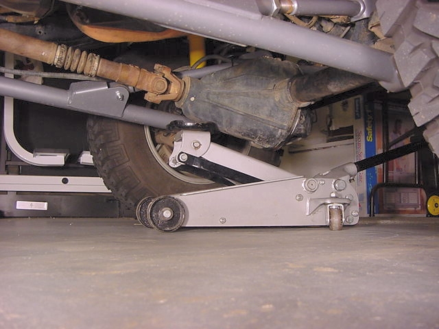
brackets. I used my bottle jack to do this, you could use another
floor jack if it was available. Remember the floor jack is still
sitting under the rear differential supporting the axle. I just
positioned the floor jack to catch the pinion yoke. I tried
just on the housing, but it kept slipping off. The axle rotated
really easy. |
 |
 |
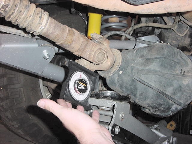
| 13. I rotated the differential up until the pinion was at about 17 degrees.
All you need to do is make certain that the drive shaft and the pinion
yoke are at the same angle. You can set the rear slightly low.
The rear differential rotates up on acceleration. |
 |
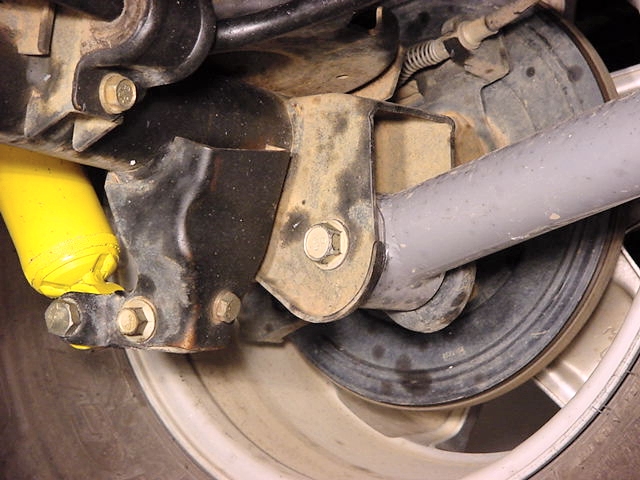
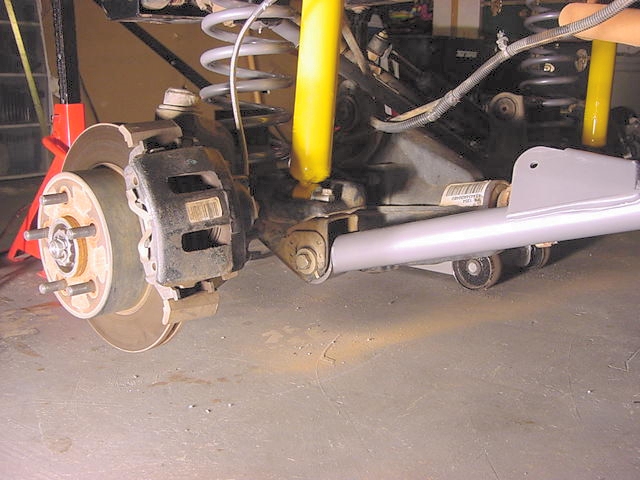
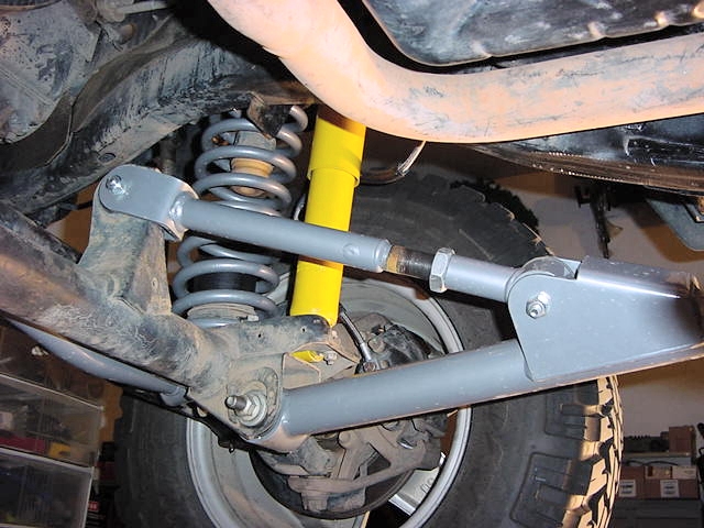
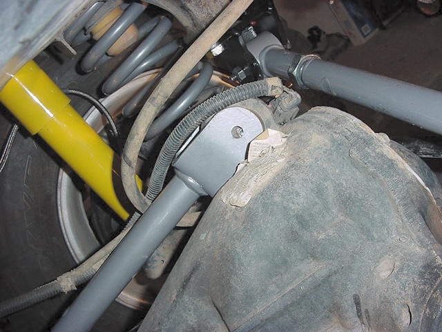
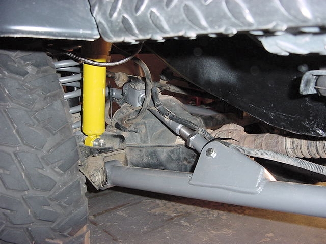
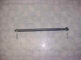
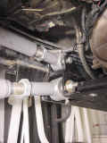
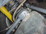
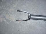
| 14. I then adjusted the upper control arms and inserted them into the
axle bracket. You will need to angle the Johnny joint to match
the angle of the axle bracket. Once you get it installed and
the holes lined up, insert the RE supplied bolt and install the washer
and nut. You will need a 17mm socket and wrench for this. |
 |
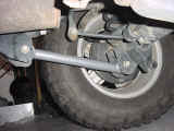
| 15. Now that you have the rear arms installed, jack up the rear end and
reinstall the tires. Remove all the floor jacks and get ready
to do the front end. |
Front
Arm Installation:
If you have the jack stands available
to support the entire vehicle in front of and behind the skid plate,
then you may want to strip the entire suspension off before you do
any cutting. This does make it easier to move the axles around.
Just be careful of things that are attached to the axle when you do
this. I decided to try it without doing this step. The
RE instructions are kind of vague on which way to do it. They
mention removing suspension items, but if you are doing the upgrade
you don't. |
| 1. I jacked up the front end and removed the tires, I then lowered the
front end down so that the front axle was almost all the way to the
ground. I supported it with jack stands underneath the front
bumper. Now I have an aftermarket bumper installed so I was
very confident that it would support the weight. I left the
floor jack under the axle. |
| 2. I did end up disconnecting the quick disconnects on the front axle
to allow it to move around a little bit. I really don't know
if it was needed, but I did this install trying to recover from the
flu, so maybe it was me. |
 |
| 3.
I installed the Zerks in the lower arms. You will need a 3/8"
wrench to install the 90deg Zerk in the adjustable section.
This section will end up having the Zerk on the top. |
 |
| 4. I then removed the lower control arm from one side. I started
with the passenger side since there wasn't a whole lot of stuff attached.
You will need a 21mm Socket and wrench (can substitute a 7/8"
wrench) for the lower control arms. You will need a 15mm
socket and wrench to get these bolt out. I left the upper arms
in until I finished cutting off the lower bracket. |
 |
| 5. Now time to break out the Power Tools. The RE instructions once
again said to remove just the lower control arm brackets. I
had learned my lesson about grinding off the weld on the outside of
the frame. Since I was feeling the greatest by this point, I
just hacked off the lower control arm brackets as close to the frame
as the sawzall would let me. I'll get the grinder out and clean
these off some time further down the road when I have more time.
Once I got them off all you need to do is grind down the edges, and
spray it with some frame black spray paint or if your like me whatever
black spray paint you had on the shelf. They actually don't
look that bad, just something that I need to clean up. |
 |
| 6. I then adjusted the lower control arm to the RE setting of 37 1/4"
(RE says 37 1/2", but I know I have to go shorter) and installed
it. You may need to remove the other lower control arm at this
point so that you can get this one in. You will need to reuse
the factory axle bracket bolt so you will need the 21mm socket and
wrench (can substitute a 7/8" wrench). If you have a cam
bolt for your front end, just set it at zero (straight up).
This was used at the factory to adjust camber and pinion angle, you
now have adjustable arms. On the skid plate side you will need
a 7/8" wrench for the nut and a 13/16" socket for the bolt
head. This is a real joy to get in. If you look at the
skid plate, you will notice that the outer hole where the bolt and
washer go through isn't quite round since it is right at the bend
point. It is a little tricky to get the washer in without dropping
it between the sections of the skid plate. If you do this by
accident, you can work the washer out with a scribe. Once I
got the control arm to line up with the hole, you will need to install
a washer on the bolt and insert the tip of the bolt into the hole,
now work the washer into the hole on the skid plate and install the
bolt the rest of the way. I then loosely installed the nuts
on both bolts, but didn't tighten them down. My length
is currently 37 1/4". I will need to readjust this when
I fine tune the suspension. I'll update the length at that time.
I intend to get it fairly close to stock length, so that when the
tire stuffs into the wheel well it will go into the center of it. |
 |
 |
| 7.
Now that you have the front lower arms installed, jack up the front
end and reinstall the tires. Remove all the floor jacks. |
| 8.
We will need to adjust your front pinion
angle. All you need to do is make certain that the drive
shaft and the pinion yoke are at the same angle. You can set
the front slightly high. The front differential rotates down
on acceleration. Once you have figured out where you need to
be, we can position the front differential and install the arms.
You may need to repeat this step as you fine tune the suspension to
your Jeep. |
|
| 9.
Place a floor jacket underneath the differential just in front of
the pinion yoke. Leave enough room for the angle gauge so that
you can check the angles. |
 |
| 10. Now remove your upper control arm. You will need a 15mm
socket and wrench to get these bolt out. Now if you are removing
your stock arms, you will also need to remove the lines running along
the driver side arm for the front locker. These lines will get
zip tied to the new lower arm. |
 |
 |
 |
| 9. At this point you should have the 2 lower control arms installed
and the upper arms removed. You will need to rotate the pinion
up to install the upper arms into the brackets. The axle rotated
really easy. |
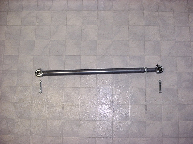
| 10.
You will use the new bolts that came with the RE kit. These
require a 17mm socket and wrench to install. These arms bolt
into the new lower arms and also into the axle brackets. You
do have the room to rotate the arm to adjust the length, so it's not
that much of a problem. My length is currently 17 1/8".
I will need to readjust this when I fine tune the suspension. |
 |
| 11..
I installed the passenger side arm first since it was the easiest. |
 |
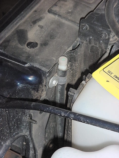
| 12.
When I went to install the driver side I first needed to sort out
all the mess of lines running to the front differential. The
biggest headache was the way they routed the vent line. I disconnected
the clamp holding the hose to the radiator with a 10mm wrench.
I then untangled it and bolted it back in. |
 |
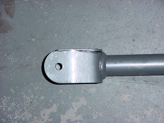
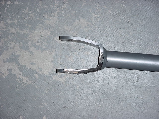
| 13. I couldn't get this arm to bolt up. I first bolted it into
the RE arm, but couldn't get it to line up with the holes in the axle
bracket. So I decided to bolt it into the axle and then the
arm. This is when I noticed what was the problem. The
front Dana 44 has a much larger housing, so the arm catches on a web
right at the top. I needed to grind down the inner bottom edge
of the axle end of the arm to allow it to clear the web. |
 |
 |
 |
 |
 |
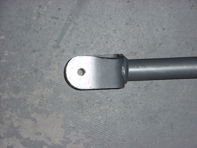
| 14. Once I got everything ground down I installed the arm. |
 |
| 15.
Before you forget, route the locker line along the lower arm and then
up the upper arm. Take a couple of zip ties and secure them
in position. |
 |
 |